Abstract
Li-ion batteries as a support for future transportation have the advantages of high storage capacity, a long life cycle, and the fact that they are less dangerous than current battery materials. Li-ion battery components, especially the cathode, are the intercalation places for lithium, which plays an important role in battery performance. This study aims to obtain the LiNixMnyCozO2 (NMC) cathode material using a simple flash coprecipitation method. As precipitation agents and pH regulators, oxalic acid and ammonia are widely available and inexpensive. The composition of the NMC mole ratio was varied, with values of 333, 424, 442, 523, 532, 622, and 811. As a comprehensive study of NMC, lithium transition-metal oxide (LMO, LCO, and LNO) is also provided. The crystal structure, functional groups, morphology, elemental composition and material behavior of the particles were all investigated during the heating process. The galvanostatic charge–discharge analysis was tested with cylindrical cells and using mesocarbon microbeads/graphite as the anode. Cells were tested at 2.7–4.25 V at 0.5 C. Based on the analysis results, NMC with a mole ratio of 622 showed the best characteristicd and electrochemical performance. After 100 cycles, the discharged capacity reaches 153.60 mAh/g with 70.9% capacity retention.
1. Introduction
Future transportation technologies are expected to be highly energy-efficient and environmentally friendly due to the rapid decrease in fossil-based fuel [1,2,3]. Green energy harvesting, as the most promising energy source, necessitates reliable energy-storage systems due to its intermittent nature, which is common in solar and wind energy. Due to their high energy and power density, Li-ion batteries have long been the primary energy storage device in electric grids and battery electric vehicles (BEV) [4,5,6,7].
The lithium transition-metal oxide group was responsible for the development of the first commercially successful electrode battery. Despite its high cost, LiCoO2 (LCO), the first commercialized Li-ion battery cathode, still has a large share in the global Li-ion battery market [8]. However, LCO is considered unstable at a high temperature, which often causes the cell to have a thermal runaway reaction [9,10]. Co also has high toxicity and the continuous exploitation may result in environmental damage [11]. Futhermore, the LCO battery’s explosion can be hazardous to humans [12]. Spinel LiMn2O4 (LMO) is gaining popularity as a battery cathode due to the drawbacks of this expensive and toxic raw material. LMO has the advantage of being nontoxic, inexpensive and easy to prepare. Futhermore, the discharge potential of this cathode material is higher than that of LCO. Due to the Jahn–Teller effect, however, the LMO capacity quickly degrades, resulting in a short life cycle [13,14,15]. Unfortunately, both electrode materials are practically unattractive regarding being used for high-power applications due to their low energy-storage capacity and short lifetime. LiNiO2 (LNO) holds great promise in providing high discharge capacities (250 mAh/g) for these applications [16]. However, the cycle instability makes the LNO less than ideal for EV.
As a result of this phenomenon, researchers are experimenting with different ways to combine the benefits of each lithium transition-metal oxide electrode [17]. One that is promising and has been applied in portable devices is lithium nickel manganese cobalt oxide (NMC). LiNixMnyCozO2 or NMC has a similar crystal structure to LCO and LNO [18]. NMC, on the other hand, has a higher specific capacity than LCO. NMC cathode material is expected to have the largest share of the battery market [19,20]. Since each metal holds a specific feature of the finished product, NMC can be modified by changing the metal ratio. The race to produce well-characterized NMC cathode material with excellent electrochemical performance continues.
A variety of methods, including solid-state, hydrothermal, spray pyrolysis, sol–gel and coprecipitation, have been used to obtain cathode material [21,22]. The coprecipitation method is widely used in producing NMC because it can provide NMC with good homogeneity and narrow particle distribution using water-soluble raw materials, which are easy to handle [23]. To precipitate the materials, the procedure requires precipitation agents. For hydroxide-based precipitation, NaOH is a common precipitation agent. However, in hydroxide-based coprecipitation, the sensitivity of nucleation and particle growth results in low particle morphology reproducibility. In addition, Mn ions are highly sensitive toward oxidation, resulting in a homogeneous mix of NMC, hence inert gas addition during the process is extremely necessary. Carbonate-based coprecipitation results in larger particle size and low homogeneity, which can cause poor electrochemical performance. Due to the reducing properties of oxalate ions, oxalic-based coprecipitation can produce fine-sized NMC with good homogeneity [24].
Studies on the synthesis of NMCs at various compositions and precipitates are presented in Table 1. Table 1 shows the total time spent on precursor preparation, calcination/pre-sintering, and sintering. Because of the differences in operating conditions, particularly for oxalate coprecipitation, research on NMC synthesis for all variations under the same conditions was undertaken. This method will provide advantages in the uniformity of synthesis and the most simple, effective, fast, and inexpensive conditions are chosen. Production of materials in a shorter time can save time and costs. Therefore, for the first time, this research proposed a facile production of various NMC cathode materials, i.e., NMC 333, NMC 424, NMC 442, NMC 532, NMC 523, NMC 622, and NMC 811 via flash oxalate coprecipitation. To study the characteristics of NMC’s in depth, lithium transition-metal oxide materials (LCO, LMO, and LNO) were also prepared. The electrochemical performance in this study was measured by a full-cell configuration using a cylindrical cell, and the result will be greatly beneficial for commercial application.

Table 1.
Various LiNixMnyCozO2 (NMC) preparation techniques.
2. Results and Discussion
2.1. Oxalate Precursor Characterization
To see the results of the precipitates and detect the presence of impurities, X-ray diffraction was used to characterize oxalate precursors at an early stage. Figure 1 depicts the entire diffraction pattern of the prepared samples. Both CoOX, MnOX, and NiOX are in orthorhombic crystal systems, as well as NMCOX. CoOX and NiOX are indexed with β-M”C2O4·2H2O, while MnOX is denominated as γ-MnC2O4·2H2O [35,36]. Therefore, all the peaks are similar to FeC2O4·2H2O. Individual phases of NiOX, MnOX and CoOX are absent in NMCOX, corresponding to the homogeneous mixing and distribution of Ni-Co-Mn at an atomic level. However, the peaks in the NMCOX, which are less sharp than that of NiOX, indicated smaller crystal sizes and fluorescence effect by the presence of cobalt and manganese atoms [36]. Testing samples with high amounts of cobalt might result in a pattern with high background noise due to fluorescence effect caused by interaction between X-rays from Cu with the cobalt-containing sample. Therefore, the XRD pattern of LCO and NMCOX111 show high noise. The lattice parameters for all samples can be seen in Table 2. The a, b, and c values follow the values reported by Oh et al. [37,38]. Nickel oxalate and cobalt oxalate have similar lattice parameters, however, manganese oxalate has different values; thus, as the nickel content of NMC-oxalate increases, the lattice parameter values will be similar to nickel oxalate.
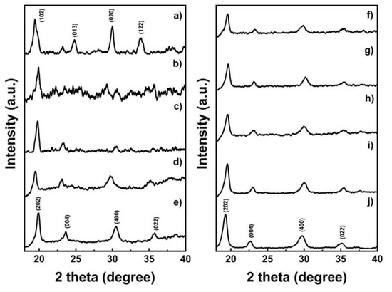
Figure 1.
X-ray diffractometer patterns of the oxalate precursor; (a) MnOX, (b) CoOX, (c) NMCOX 333, (d) NMCOX 424, (e) NMCOX 442, (f) NMCOX 523, (g) NMCOX 532, (h) NMCOX 622, (i) NMCOX 811, and (j) NiOX.
Table 2.
Lattice parameter of the oxalate precursor.
Figure 2 shows the mid-IR region (4000–400/cm) absorbance spectra of all the precursor samples as supporting data for the X-ray diffraction pattern. The absorbance of all the samples was the same. The bending vibrations of O-H are responsible for the broad peaks at around 3300–3500/cm and 1600/cm. The sharp peak located at about 1300/cm corresponds to the C-O bond [39,40,41]. The peaks between 600 and 800/cm indicate C-O and O-C = O bonds. The presence of C-O and O-H peaks indicates that there was direct contact between the sample and air during preparation [21]. The metal oxide (M-O) bond, which is in the metal oxalate phase, also has a peak around 490/cm [42]. The FTIR results of the NMCOX samples are comparable to those of FeC2O4·2H2O, indicating that the precipitation of NMC-oxalate occurs with the reaction given in Equations (1) and (2), as indicated by the X-ray diffraction results.
xNi2+(aq) + yMn2+(aq) + zCo2+(aq) + NH4OH(aq) ⇌ NixMnyCoz(NH3)2+(aq) + H2O(l)
NixMnyCoz(NH3)2+(aq) + H2C2O4(aq) →NixMnyCozC2O4↓(s) + NH4+(aq) + H+(aq)
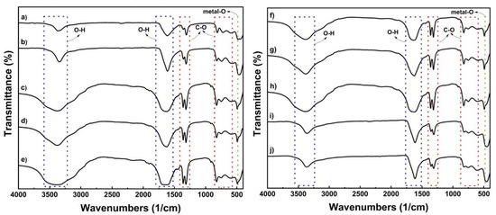
Figure 2.
FTIR spectra of the oxalate precursor; (a) MnOX, (b) CoOX, (c) NMCOX 333, (d) NMCOX 424, (e) NMCOX 442, (f) NMCOX 523, (g) NMCOX 532, (h) NMCOX 622, (i) NMCOX 811, and (j) NiOX.
In the absorbance spectra test, it was discovered that the sample contains an O-H group in the form of water. Thermogravimetric analysis (TGA) was used to perform a thermal analysis to determine the amount of water in the sample. Figure 3 shows weight loss through two stages, at temperatures around 200–250 °C and 320–400 °C. The weight loss at stage one is associated with dehydration of the precursor to anhydrous compound [43]. Because the sample loses 19.7% of its weight, the precipitants formed are NMC-oxalate dihydrate and nickel oxalate dihydrate, which can be confirmed [43,44,45]. Then, in stage two, the weight loss is 40% due to the decomposition of the NMC-oxalate to the NMC-oxide [38]. The reactions in these two stages are shown in Equations (3) and (4) [44]. This phenomenon is also explained in Table 3, which shows the temperature of the dehydration and decomposition stages of the precursor, including those reported in previous studies. The calcination process began at a slightly different temperature for each sample, but the nickel content tended to differ. The calcination temperature drops as the nickel content (Ni-rich material) rises [46].
Stage 1: MC2O4·2H2O → MC2O4 + 2H2O
Stage 2: MC2O4 → MO + CO + CO2
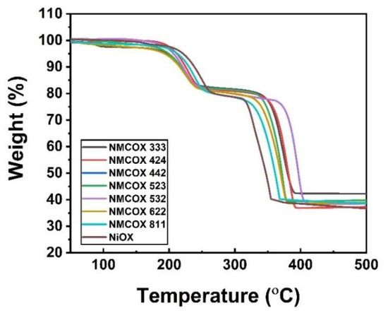
Figure 3.
Thermal analysis of NiOX and NMCOX.
Table 3.
The temperature in the dehydration and decomposition stages of the precursor.
2.2. Cathode Material’s Characterization
The lithiated and heated product from the coprecipitation process is then used. The final product in the cathode material is then characterized in order to determine the material that has been formed. The first test, as in the previous characterization, is X-ray diffraction, as shown in Figure 4. X-ray Diffractometer (XRD) patterns of LCO, NMC, and LNO samples prepared after heat treatment showed a hexagonal structure, such as layered α-NaFeO2 (space group: R3 m). All peaks conform to the JCPDS LiNiO2 card with no observable phase impurities [47,48]. However, for NMC 333, LNO, LCO and LMO, Li2CO3 was detected in the material. To compensate the Li loss during high-temperature lithiation (at 800 °C), an excess of Li source was added. In samples with high content of Co and Mn, which usually form a layered structure at high temperatures, it can be predicted that the formation of layer-structured material is not completed due to nonoptimal sintering temperature. On the contrary, the formation of Ni-rich, especially Ni-based, cathode material, is optimal in lower temperature. Therefore, at 800 °C, the formation of rock-salt NiO was favorable, and this hampered the lithiation process which predicted the unsuccessful lithiation process. These phenomena cause the formation of Li2CO3 phase on the sample. Meanwhile, LMO shows a cubic spinel structure with space group Fd3m (the lattice parameter a = b = c) [49]. The double peak at (006)/(102) and (018)/(110) corresponds to a well-ordered layered structure [22,23]. Especially for NMC, a double peak can be clearly seen at 2θ 38.4°–38.5° for (006)/(102) and 64.5°–65.5° for (018)/(110).
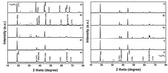
Figure 4.
X-ray Diffractometer (XRD) patterns of the sample; (a) LMO, (b) LCO, (c) NMC 333, (d) NMC424, (e) NMC442, (f) NMC523, (g) NMC532, (h) NMC 622, (i) NMC 811, and (j) NMC 811.
The lattice parameter and the R value presented in Table 4 can be used to evaluate the well-ordered, layered material. The lattice parameters of each sample were calculated using the least-squares regression method [21]. The c/a value of the lattice parameter indicates the crystallization of the material. The ideal value of c/a is above 4.899 [50]. Both NMC and LNO samples had values above the ideal c/a ratio, which meant that the samples had a well-ordered layered structure. The relative intensity of certain peaks in XRD indicates the degree of antisite interference of Ni2+ and Li+. Furthermore, a good hexagonal ordering of the lattice has an R value below 0.45 [50]. All samples had R values less than 0.45, with the exception of NMC 811. Electrochemical performance can be improved by lowering antisite interference values [51].
Table 4.
The lattice parameter of LMO, LCO, LNO, and NMC at various compositions.
Calculating the intensity ratio (IR) can reveal the presence of cation mixing, which is common in layered transition-metal oxide cathode materials. IR for LCO, NMC, and LNO uses peaks (003) and (104), while for LMO it uses peaks (111) and (311), and the results are listed in Table 4. The IR value of each sample is more than 1.2, except for LCO, which has a low degree of cation mixing [52]. The occurrence of cation mixing mostly occurs at higher Ni content. In the transition-metal lattice, the Ni2+ will substitute the Li-ion due to their similarity in radii size [53]. In this case, the IR value does not significantly change as the Ni content increases. This could be due to the presence of Co and Mn, which are still capable of allowing NMC samples to be structurally stabilized.
Figure 5 shows an FT-IR spectrum analysis of the presence of anionic impurities on the surface of cathode material samples. On the basis of spectra, the carbonate compound is only visible (~900/cm and ~1400/cm). This can be attributed to Li2CO3 as a result of excess Li source. The peak should indicate the oxide phase only, but there is another phase that can be observed that is not attributed to the metal oxide phase. These phase is the result of the absorption of molecules in the atmosphere in the sample. During the heating process, Li2CO3 is melted and decomposed, releasing CO2. However, residual Li was converted back into Li2CO3 as the sintering process was finished [21]. The equation depicts the formation of Li2CO3 on the surface of samples (5,6). At NMC 333 and LNO, where the peak is sharp and clear, these spectra support the suspicion of impurity. Since the presence of Li2CO3 is considered low, it can be neglected.
Li2O + H2O → 2LiOH
2LiOH + CO2 → Li2CO3 + H2O
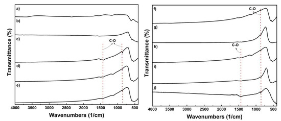
Figure 5.
FTIR spectra of the sample; (a) LMO, (b) LCO, (c) NMC 333, (d) NMC424, (e) NMC442, (f) NMC523, (g) NMC532, (h) NMC 622, (i) NMC 811, and (j) NMC 811.
At temperatures of 46–200 °C and 250–400 °C, Figure 6 depicts weight loss in two stages. The loss of adsorbed water on the material’s surface and the intercalation of several water and alcohol molecules are responsible for 9.8% of the weight loss in stage one. In stage two, the weight loss of 25% is due to the reaction between lithium oxide, nickel oxide, manganese oxide, and cobalt oxide. Then, the sample weight starts to be constant at ~450 °C. This weight loss can confirm that the formation of NMC crystals has occurred [54]. It is also reinforced by the DSC curve in Figure S1, to determine the optimal calcination temperature. Three peaks between 60–360 °C indicate an exothermic state that affects the loss of water in the material due to evaporation [55]. To confirm the TG curve, the lithiation process begins at 460 °C. Based on the curve, the final mass is consistent with the theoretical value of ~42%.
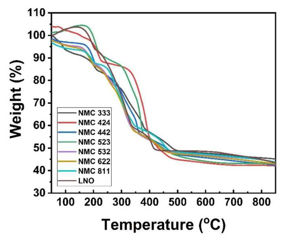
Figure 6.
Thermal analysis of LNO and NMC at various compositions.
Scanning Electron Microscope (SEM) testing was used to determine the morphology of the sample after the heating process as shown in Figure 7. Most samples have nanosized-to-submicron-sized primary particles clustered together to form microsized secondary particles. Compared to before the heating and lithiation process, the particle shape did not change significantly, for example in NMCOX 622 and NMCOX 811 in Figure S2. Small agglomerated cubes were found in the NMC 622, NMC 811, and LCO samples. The particles in NMC samples 333, 424, 442, 523, and 532 were quasispherical. LNO has a chunk morphology and LMO has an irregular shape. All samples have a primary particle size ≤1.5 µm, while for secondary particles, the variations are presented in Table 5.
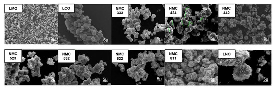
Figure 7.
Scanning Electron Microscope images x5000 magnification of LMO, LCO, LNO, and NMC at various compositions.
Table 5.
Particle size.
Table 6 presents the XRF result of the as-prepared samples for NMC. This XRF data is based on three atoms, namely Ni, Mn and Co. The nickel content of NMC 333, NMC 523, NMC 532, and NMC 622 is a little far from the expected nickel content. Meanwhile, NMC 424, NMC 442, NMC 622 and NMC 811 are close to the expected values. Similarly, except for the NMC 622 sample, which had a lower Co content, the Mn and Co content in all samples was close to the expected value.
Table 6.
Ni–Mn–Co content of as-prepared samples.
2.3. Electrochemical Performance Test
A cylindrical battery cell was used to test the NMC cathode material electrochemically. As the anode, mesocarbon microbeads (MCMB) (MTI, America) were used to test the charge–discharge analysis. Before grading, the formation cycle of the NMC battery sample was completed; data are not shown. Then, the specific capacity is determined after three cycles. The charge–discharge curves created using a current density of 0.5 C are depicted in Figure 8.
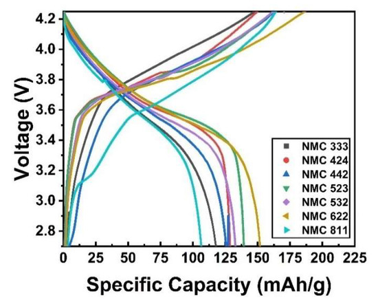
Figure 8.
Charge–discharge analysis of as-prepared samples.
The specific discharge capacity of NMC 333, NMC 424, NMC 442, NMC 523, NMC 532, NMC 622 and NMC811 is 120.20 mAh/g, 129.43 mAh/g, 127.30 mAh/g, 140.04 mAh/g, 134.22 mAh/g, 153.60 mAh/g and 106.30 mAh/g, respectively, as shown in Figure 8. NMC622 delivers a higher specific discharge capacity due to its high nickel content; meanwhile, NMC811 needs different synthesis conditions. NMC cathode material has active electrochemical ions, Ni2+ and Co3+. The oxidation of Ni2+ must follow charge compensation during lithium extraction (i.e., charging) to Ni3+ and Ni4+, and Co3+ to Co4+, respectively [56]. Since the Ni3+ and Ni4+ ions are converted to Ni2+ ions when heated, oxygen release from the structure is unavoidable to maintain charge neutrality. The temperature ranges for the LiMn2O4-type and Mn3O4-type spinel for each sample are similar to the temperature range for oxygen release spreading. The lower the onset temperature of oxygen release and the tighter the oxygen distribution, the higher the nickel content [57]. Thus, NMC811 needs an extra oxygen environment in the heating process. The same method is used to make LCO, which has a specific capacity of 92 mAh/g (data not shown). As a result, when compared to LCO, it can be concluded that the sample performs exceptionally well.
Using a standard research protocol, Figure 9 depicts the rate ability of various NMC samples. The real specific capacity (C’) rather than the theoretical capacity (C) is used to determine the charging and discharging rate. After three cycles of the formation process (not shown), the cells were charged at 0.5 C’ and discharged at different discharging rates. Even after being discharged at high currents, the graph shows that all samples have a small capacity reduction, as reported by Schmidt et al. [58]. This behavior indicates that the prepared sample has a good cycling performance. Since NMC622 has a higher specific discharge capacity, Figure 10b shows its cycling behavior for 100 cycles at 1 C’ rates, and its capacity retention of 70.9%. The cycling performance of NMC532 and NMC442 are also shown in Figure 10a and have capacity retention of 86.1% and 72.6%, respectively. More research is needed to obtain better and more stable capacity and lower capacity retention.
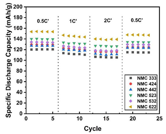
Figure 9.
Rate-ability analysis of as-prepared samples.
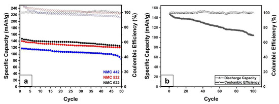
Figure 10.
Cycle-ability analysis of; (a) NMC 442, NMC 532, and NMC 622 at 1 C’ for 50 cycles, (b) NMC622 at 1 C’ for 100 cycles.
NMC622 is a highly recognizable and well-studied material due to its excellent electrochemical performance. Several studies on NMC622 and its electrochemical performance are listed in Table 7. Compared to full-cell, half-cell electrochemical studies are reported more frequently. However, this study uses full cells because they are closer to commercial applications. This research can be a reference for the development of a simpler, faster, and more effective synthesis of NMC, especially NMC622, in the future.
Table 7.
State-of-the-art performance metrics of NMC622.
2.4. Postmortem Analysis
To determine the state of the material after the cycle, a postmortem analysis was performed. Cycling causes capacity degradation, as shown in Figure 10. Loss of active material due to structural degradation, loss of reversible lithium, and increased resistance, all contribute to capacity degradation [64]. The structural degradation can be seen through XRD and FTIR analysis presented in Figure 11. In Figure 11a, impurities in the form of Li2CO3 are seen at 2θ 27.8°. The formation of Li2CO3 occurs due to a side reaction between the electrolyte and the cathode material. Furthermore, due to a decrease in crystallinite, the postcycle sample appears to be wider than the precycle sample [21]. The emergence of Li2CO3 impurities is also supported by the FTIR analysis shown in Figure 11b. FTIR spectra show Li2CO3 at wavenumbers 838/cm, 1397/cm and 1480/cm. ROCO2Li (1634/cm) and ROLi (1073/cm) were also found on the surface of the material. The large amount of Li2CO3 formed causes a large reversible Li loss [64]. In terms of morphology, the presence of a solid electrolyte interphase layer covering the particle surface can be seen in postcycle in Figure 12. The decomposition of organic electrolytes results in the formation of this layer [65].
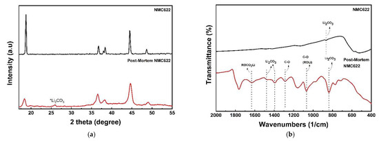
Figure 11.
Postmortem analysis of NMC622; (a) X-ray Diffractometer pattern and (b) FTIR spectra.
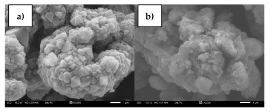
Figure 12.
Scanning Electron Microscope images ×10000 magnification of NMC622; (a) Precycle, (b) Postcycle.
3. Materials and Methods
3.1. Material Synthesis
The transition-metal oxalate of LiMn2O4 (LMO), LiCoO2 (LCO), and LiNiO2 (LNO) were synthesized by a precipitation method. Nickel sulfate hexahydrate/NiSO4·6H2O (Zenith, Sao Paulo, Brazil), cobalt sulfate heptahydrate (CoSO4·7H2O) (Rubamin, Vadodara, India), and manganese sulfate monohydrate (MnSO4·H2O) (Yaolong Chem, Deyang, China) were used as raw materials to create the transition-metal oxalate without any purification. MnSO4·H2O was dissolved in deionized water with a concentration of 2 M solution at 60 °C and with stirring at 600 rpm. H2C2O4·2H2O (YC Chemicals, Shenzhen, China) as a precipitating agent was also dissolved in deionized water equimolarly. Then, the H2C2O4·2H2O solution was mixed with MnSO4·H2O solution, and maintained at a constant temperature for 30 min. The resulting material was precipitated, washed to neutral pH, filtered, and dried in an oven overnight at a temperature of 150 °C. MnOX is the abbreviation for transition-metal oxalate dihydrate precipitant. CoOX and NiOX are the transition-metal oxalate of LCO and LNO, which are synthesized using the same process.
NiSO4, CoSO4, and MnSO4 were directly used without any purification as the ternary-metal source for NMC. By stirring with deionized water and heating at 60 °C, a stoichiometric amount of Ni–Mn–Co salt was dissolved. To obtain a complex solution, equimolar ammonia (Merck) was added after a stable solution had been achieved. On the other hand, an equimolar amount of 2 M H2C2O4·2H2O solution was prepared. Then, the H2C2O4·2H2O solution was mixed into the Ni–Co–Mn salt solution until a pH of 2 was reached. For 2h, the temperature and pH were kept constant. The resulting material was precipitated, washed until neutral pH, filtered, and dried in the oven overnight at a temperature of 150 °C. The NMC-oxalate samples were denoted as NMCOX 333, NMCOX 424, NMCOX 442, NMCOX 523, NMCOX 532, NMCOX 622, and NMCOX 811 in respect to the composition of the ternary transition metal.
The dried MnOX, CoOX, NiOX, and NMCOX were mixed by hand milling with LiOH·H2O (Leverton, India) with ternary metal to a Li ratio of 1:1.05 until homogenous. Then, it was calcinated for 6 h at 600 °C and sintered for 12 h at 800 °C in a muffle furnace under an air atmosphere. The obtained fine powder was sieved using a 200-screen mesh. The finished products were labeled as LMO, LCO, LNO, NMC 333, NMC424, NMC 442, NMC 523, NMC 532, NMC622, and NMC 811.
3.2. Material Characterization
Fourier Transform Infrared (FTIR) spectroscopy (Shimadzu FTIR Spectrometer, Japan) was used to look for functional groups and surface chemistry in precursor and NMC product samples. Structural properties of powders were investigated using X-Ray Diffractometer (XRD) (D2-Phaser Bruker, Germany) using CuKα radiation at a diffraction angle of 10 < 2θ < 80° and scanning rate of 0.02°/s using λ = 1.5406 Ǻ. The morphology and particle size of the sample were examined using a Scanning Electron Microscope (SEM) (JCM 7000, JEOL). The Ni, Mn and Co elements’ compositions in the powders were evaluated by X-Ray Fluoroscopy (Bruker XRF Spectrometer, Germany). The material behavior during heating was investigated using Thermogravimetric analysis (TGA) (TGA-209F3, NETZSCH, Germany) in a temperature range of 50 to 900 °C under airflow.
3.3. Cell Assembly and Electrochemical Testing
In an 18650-type cylindrical battery, the electrochemical performance was tested. Commercial MCMB (MTI, America) were used as the graphite anode. As a binder and conductive agent, MTI America’s polyvinylidene fluoride (PVDF) and carbon black (CB) were used, respectively. Meanwhile, lithium-ion transport between the cathode and anode used LiPF6 in ethylene carbonate (EC):diethyl carbonate (DEC):dimethyl carbonate (DMC) = 1:1:1, v/v (MTI, China) electrolyte. To sustain reproducible data, the cells were designed with an N/P ratio of 1.2; thus, the cathode weight became the calculation basis for specific capacity measurements. Electrode preparation was started by dispersing the active material (LMO, LCO, NMC, and LNO) with CB and PVDF at a ratio of material: CB: PVDF = 90:4:6 in a nonaqueous N-Methyl-2-pyrrolidone (NMP) solvent to form a homogenous paste. To ensure complete drying, the slurry was laminated on the front and back of Al foil using an automatic film coater (MTI, USA) with an adjusted thickness of 200 µm, and stored in a vacuum oven at 120 °C for 1 h. The mass loading of the electrode was ~20 mg/cm2. Before cell assembly, the electrodes were stored in an oven at 80 °C. The assembly of the cylindrical cells was performed similarly to our previous study [21]. The NEWARE battery analyzer and BTS Software were used to measure the galvanostatic charge–discharge capacity of cells. The recorded capacity of cells was obtained between 2.7 and 4.25 V at 0.5 C or 100 mA/g (1C = 200 mA/g). The rate-ability test also uses the NEWARE battery analyzer and BTS software with charge and discharge rates determined using the actual specific capacity (Cactual = C’). The actual specific capacity (C’) is defined as the theoretical specific capacity (C)/mass.
4. Conclusions
Firstly, highly crystalline, well-ordered, layered, hexagonal structured LiNixMnyCozO2 cathode materials with various compositions were successfully synthesized via flash oxalate coprecipitation of ternary transition-metal sulfates. According to XRD and FTIR measurements, the oxalate precursors have no impurity phase. The layered lithium metal oxide structures can be seen in the XRD spectra of the as-obtained sample. SEM images confirm microsized, quasispherical-shaped particles. The NMC622 has the highest NMC specific discharge capacity of 153.60 mAh/g at 0.5 C. Overall, the flash coprecipitation method is considered promising regarding adaptation for a variety of NMCs, and suitable to be applied for their mass production.
Supplementary Materials
The following are available online at https://www.mdpi.com/article/10.3390/batteries8010004/s1, Figure S1: TG/DSC Analysis of NMC 622, Figure S2: SEM Images x5000 magnification of NMCOX 622 and NMCOX 811.
Author Contributions
Conceptualization, S.S.N., M.R. and A.P.; methodology, S.S.N., H.S.O. and S.U.M.; data curation, S.S.N., M.R. and C.S.Y.; writing—original draft preparation, S.S.N. and M.R.; writing—review and editing, H.S.O. and A.P.; visualization, C.S.Y., H.N. (Hanida Nilasary), H.N. (Hartoto Nursukatmo) and S.U.M.; supervision, H.N. (Hanida Nilasary), H.N. (Hartoto Nursukatmo) and A.P. All authors have read and agreed to the published version of the manuscript.
Funding
This research was funded by Indonesia Endowment Fund for Education (LPDP/Lembaga Pengelola Dana Pendidikan) through Pendanaan Riset Inovatif Produk (Rispro), grant number PRJ-6/LPDP/2020 and PT Pertamina (contract number 007/P00000/2019-S0).
Institutional Review Board Statement
Not applicable.
Informed Consent Statement
Not applicable.
Data Availability Statement
All collected data are presented in the manuscript.
Conflicts of Interest
The authors declare no conflict of interest.
References
- Kåberger, T. Progress of renewable electricity replacing fossil fuels. Prog. Renew. Electr. Replac. Foss. Fuels 2018, 1, 48–52. [Google Scholar] [CrossRef]
- Van Mierlo, J.; Maggetto, G.; Lataire, P. Which energy source for road transport in the future? A comparison of battery, hybrid and fuel cell vehicles. Energy Convers. Manag. 2006, 47, 2748–2760. [Google Scholar] [CrossRef]
- Offer, G.J.; Howey, D.; Contestabile, M.; Clague, R.; Brandon, N.P. Comparative analysis of battery electric, hydrogen fuel cell and hybrid vehicles in a future sustainable road transport system. Energy Policy 2010, 38, 24–29. [Google Scholar] [CrossRef] [Green Version]
- Dunn, B.; Kamath, H.; Tarascon, J.M. Electrical energy storage for the grid: A battery of choices. Science 2011, 334, 928–935. [Google Scholar] [CrossRef] [Green Version]
- Miao, Y.; Hynan, P.; Von Jouanne, A.; Yokochi, A. Current li-ion battery technologies in electric vehicles and opportunities for advancements. Energies 2019, 12, 1074. [Google Scholar] [CrossRef] [Green Version]
- Jaiswal, A. Lithium-ion battery based renewable energy solution for off-grid electricity: A techno-economic analysis. Renew. Sustain. Energy Rev. 2017, 72, 922–934. [Google Scholar] [CrossRef]
- Berckmans, G.; Messagie, M.; Smekens, J.; Omar, N.; Vanhaverbeke, L.; Mierlo, J. Van Cost projection of state of the art lithium-ion batteries for electric vehicles up to 2030. Energies 2017, 10, 1314. [Google Scholar] [CrossRef] [Green Version]
- Wang, L.; Chen, B.; Ma, J.; Cui, G.; Chen, L. Reviving lithium cobalt oxide-based lithium secondary batteries-toward a higher energy density. Chem. Soc. Rev. 2018, 47, 6505–6602. [Google Scholar] [CrossRef]
- Jhu, C.Y.; Wang, Y.W.; Wen, C.Y.; Shu, C.M. Thermal runaway potential of LiCoO2 and Li(Ni1/3Co1/3Mn1/3)O2 batteries determined with adiabatic calorimetry methodology. Appl. Energy 2012, 100, 127–131. [Google Scholar] [CrossRef]
- Feng, X.; Ouyang, M.; Liu, X.; Lu, L.; Xia, Y.; He, X. Thermal runaway mechanism of lithium ion battery for electric vehicles: A review. Energy Storage Mater. 2018, 10, 246–267. [Google Scholar] [CrossRef]
- Scharf, B.; Clement, C.C.; Zolla, V.; Perino, G.; Yan, B.; Elci, S.G.; Purdue, E.; Goldring, S.; MacAluso, F.; Cobelli, N.; et al. Molecular analysis of chromium and cobalt-related toxicity. Sci. Rep. 2014, 4, 5729. [Google Scholar] [CrossRef] [Green Version]
- Sironval, V.; Reylandt, L.; Chaurand, P.; Ibouraadaten, S.; Palmai-Pallag, M.; Yakoub, Y.; Ucakar, B.; Rose, J.; Poleunis, C.; Vanbever, R.; et al. Respiratory hazard of Li-ion battery components: Elective toxicity of lithium cobalt oxide (LiCoO2) particles in a mouse bioassay. Arch. Toxicol. 2018, 92, 1673–1684. [Google Scholar] [CrossRef] [PubMed]
- Michalska, M.; Ziółkowska, D.A.; Jasiński, J.B.; Lee, P.H.; Ławniczak, P.; Andrzejewski, B.; Ostrowski, A.; Bednarski, W.; Wu, S.H.; Lin, J.Y. Improved electrochemical performance of LiMn2O4 cathode material by Ce doping. Electrochim. Acta 2018, 276, 37–46. [Google Scholar] [CrossRef]
- Zhu, Q.; Zheng, S.; Lu, X.; Wan, Y.; Chen, Q.; Yang, J.; Zhang, L.Z.; Lu, Z. Improved cycle performance of LiMn2O4 cathode material for aqueous rechargeable lithium battery by LaF3 coating. J. Alloys Compd. 2016, 654, 384–391. [Google Scholar] [CrossRef]
- Cai, Z.; Ma, Y.; Huang, X.; Yan, X.; Yu, Z.; Zhang, S.; Song, G.; Xu, Y.; Wen, C.; Yang, W. High electrochemical stability Al-doped spinel LiMn2O4 cathode material for Li-ion batteries. J. Energy Storage 2020, 27, 101036. [Google Scholar] [CrossRef]
- Yoon, C.S.; Kim, U.H.; Park, G.T.; Kim, S.J.; Kim, K.H.; Kim, J.; Sun, Y.K. Self-Passivation of a LiNiO2 Cathode for a Lithium-Ion Battery through Zr Doping. ACS Energy Lett. 2018, 3, 1634–1639. [Google Scholar] [CrossRef]
- Li, M.; Lu, J. Cobalt in lithium-ion batteries. Science 2020, 367, 979–980. [Google Scholar] [CrossRef]
- Yang, H.; Savory, C.N.; Morgan, B.J.; Scanlon, D.O.; Skelton, J.M.; Walsh, A. Chemical Trends in the Lattice Thermal Conductivity of Li(Ni, Mn, Co)O2(NMC) Battery Cathodes. Chem. Mater. 2020, 32, 7542–7550. [Google Scholar] [CrossRef]
- Olivetti, E.A.; Ceder, G.; Gaustad, G.G.; Fu, X. Lithium-Ion Battery Supply Chain Considerations: Analysis of Potential Bottlenecks in Critical Metals. Joule 2017, 1, 229–243. [Google Scholar] [CrossRef] [Green Version]
- Pelegov, D.V.; Pontes, J. Main drivers of battery industry changes: Electric vehicles—A market overview. Batteries 2018, 4, 65. [Google Scholar] [CrossRef] [Green Version]
- Yudha, C.S.; Muzayanha, S.U.; Hendri, W.; Iskandar, F.; Sutopo, W.; Purwanto, A.; Widiyandari, H.; Iskandar, F.; Sutopo, W.; Purwanto, A. Synthesis of LiNi0.85Co0.14Al0.01O2 Cathode Material and its Performance in an NCA/Graphite Full-Battery. Energies 2019, 12, 1886. [Google Scholar] [CrossRef] [Green Version]
- Hamad, K.I.; Xing, Y. Stabilizing Li-rich NMC materials by using precursor salts with acetate and nitrate anions for Li-ion batteries. Batteries 2019, 5, 69. [Google Scholar] [CrossRef] [Green Version]
- Zha, G.; Hu, W.; Agarwal, S.; Ouyang, C.; Hu, N.; Hou, H. High performance layered LiNi0.8Co0.07Fe0.03Mn0.1O2 cathode materials for Li-ion battery. Chem. Eng. J. 2021, 409, 128343. [Google Scholar] [CrossRef]
- Dong, H.; Koenig, G.M. A review on synthesis and engineering of crystal precursors produced: Via coprecipitation for multicomponent lithium-ion battery cathode materials. Cryst. Eng. Comm. 2020, 22, 1514–1530. [Google Scholar] [CrossRef]
- Yin, K.; Fang, W.; Zhong, B.; Guo, X.; Tang, Y.; Nie, X. The effects of precipitant agent on structure and performance of LiNi1/3Co1/3Mn1/3O2 cathode material via a carbonate co-precipitation method. Electrochim. Acta 2012, 85, 99–103. [Google Scholar] [CrossRef]
- Zhang, S.; Deng, C.; Yang, S.Y.; Niu, H. An improved carbonate co-precipitation method for the preparation of spherical Li[Ni1/3Co1/3 Mn1/3]O2 cathode material. J. Alloys Compd. 2009, 484, 519–523. [Google Scholar] [CrossRef]
- Li, J.; Li, H.; Stone, W.; Weber, R.; Hy, S.; Dahn, J.R. Synthesis of Single Crystal LiNi0.5Mn0.3Co0.2O2 for Lithium Ion Batteries. J. Electrochem. Soc. 2017, 164, A3529–A3537. [Google Scholar] [CrossRef]
- Eilers-Rethwisch, M.; Winter, M.; Schappacher, F.M. Synthesis, electrochemical investigation and structural analysis of doped Li[Ni0.6Mn0.2Co0.2-xMx]O2 (x = 0, 0.05; M = Al, Fe, Sn) cathode materials. J. Power Sources 2018, 387, 101–107. [Google Scholar] [CrossRef]
- Zhang, N.; Li, J.; Li, H.; Liu, A.; Huang, Q.; Ma, L.; Li, Y.; Dahn, J.R. Structural, Electrochemical, and Thermal Properties of Nickel-Rich LiNixMnyCozO2 Materials. Chem. Mater. 2018, 30, 8852–8860. [Google Scholar] [CrossRef]
- Xu, L.; Zhou, F.; Kong, J.; Chen, Z.; Chen, K. Synthesis of Li(Ni0.6Co0.2Mn0.2)O2 with sodium DL-lactate as an eco-friendly chelating agent and its electrochemical performances for lithium-ion batteries. Ionics 2018, 24, 2261–2273. [Google Scholar] [CrossRef]
- Yang, Z.; Lu, J.; Bian, D.; Zhang, W.; Yang, X.; Xia, J.; Chen, G.; Gu, H.; Ma, G. Stepwise co-precipitation to synthesize LiNi1/3Co1/3Mn1/3O2one-dimensional hierarchical structure for lithium ion batteries. J. Power Sources 2014, 272, 144–151. [Google Scholar] [CrossRef]
- Zhu, J.; Yan, J.; Zhang, L. High specific capacity Mg-doping LiNi1/3Mn1/3Co1/3O2 cathode materials synthesised by a simple stepwise co-precipitation method. Micro Nano Lett. 2019, 14, 129–132. [Google Scholar] [CrossRef]
- Yao, X.; Xu, Z.; Yao, Z.; Cheng, W.; Gao, H.; Zhao, Q.; Li, J.; Zhou, A. Oxalate co-precipitation synthesis of LiNi0.6Co0.2Mn0.2O2 for low-cost and high-energy lithium-ion batteries. Mater. Today Commun. 2019, 19, 262–270. [Google Scholar] [CrossRef]
- Wu, C.Y.; Bao, Q.; Tsai, Y.T.; Duh, J.G. Tuning (003) interplanar space by boric acid co-sintering to enhance Li+ storage and transfer in Li(Ni0.8Co0.1Mn0.1)O2 cathode. J. Alloys Compd. 2021, 865, 158806. [Google Scholar] [CrossRef]
- Amutha, R.; Akilandeswari, S.; Muruganandham, M.; Sillanpää, M.; Ahmmad, B.; Ohkubo, T. Template-free synthesis of self-assembled Co3O4 micro/nanocrystals. J. Nanosci. Nanotechnol. 2011, 11, 3171–3179. [Google Scholar] [CrossRef]
- Dong, H.; Koenig, G.M. Compositional control of precipitate precursors for lithium-ion battery active materials: Role of solution equilibrium and precipitation rate. J. Mater. Chem. A 2017, 5, 13785–13798. [Google Scholar] [CrossRef]
- Oh, H.J.; Jo, C.H.; Yoon, C.S.; Yashiro, H.; Kim, S.J.; Passerini, S.; Sun, Y.K.; Myung, S.T. Nickel oxalate dihydrate nanorods attached to reduced graphene oxide sheets as a high-capacity anode for rechargeable lithium batteries. NPG Asia Mater. 2016, 8, e270. [Google Scholar] [CrossRef] [Green Version]
- Tang, W.; Wu, X.; Li, D.; Wang, Z.; Liu, G.; Liu, H.; Chen, Y. Oxalate route for promoting activity of manganese oxide catalysts in total VOCs’ oxidation: Effect of calcination temperature and preparation method. J. Mater. Chem. A 2014, 2, 2544–2554. [Google Scholar] [CrossRef]
- Nayaka, G.P.; Zhang, Y.; Dong, P.; Wang, D.; Zhou, Z.; Duan, J.; Li, X.; Lin, Y.; Meng, Q.; Pai, K.V.; et al. An environmental friendly attempt to recycle the spent Li-ion battery cathode through organic acid leaching. J. Environ. Chem. Eng. 2019, 7, 102854. [Google Scholar] [CrossRef]
- Dhayal Raj, A.; Suresh Kumar, P.; Mangalaraj, D.; Ponpandian, N.; Albert Irudayaraj, A.; Yang, Q. Gas sensing behavior of high surface area Co3O4 Micro/Nano structures synthesized by simple sonication process. Sens. Lett. 2012, 10, 826–832. [Google Scholar] [CrossRef]
- Nandiyanto, A.B.D.; Oktiani, R.; Ragadhita, R. How to read and interpret ftir spectroscope of organic material. Indones. J. Sci. Technol. 2019, 4, 97–118. [Google Scholar] [CrossRef]
- Jung, I.; Choi, J.; Tak, Y. Nickel oxalate nanostructures for supercapacitors. J. Mater. Chem. 2010, 20, 6164–6169. [Google Scholar] [CrossRef]
- Małecka, B.; Małecki, A.; Drozdz-Cieśla, E.; Tortet, L.; Llewellyn, P.; Rouquerol, F. Some aspects of thermal decomposition of NiC2O4·2H2O. Thermochim. Acta 2007, 466, 57–62. [Google Scholar] [CrossRef]
- Shen, B.B.; Shen, H.; Pan, Y.; Chen, T. The Thermal Decomposition of NiC2O4 2H2O: An In situ TP-XRD and TGA/FT-IR Study. Oldenbourg Wissenschaftsverlag 2001, 1418, 1413–1418. [Google Scholar] [CrossRef]
- Zhan, D.; Cong, C.; Diakite, K.; Tao, Y.; Zhang, K. Kinetics of thermal decomposition of nickel oxalate dihydrate in air. Thermochim. Acta 2005, 430, 101–105. [Google Scholar] [CrossRef]
- Langdon, J.; Manthiram, A. A perspective on single-crystal layered oxide cathodes for lithium-ion batteries. Energy Storage Mater. 2021, 37, 143–160. [Google Scholar] [CrossRef]
- Murali, N.; Babu, K.V.; Babu, K.E.; Veeraiah, V. Structural characterization of LiNiO2 and LiNi0.96Mg0.04O2 cathode materials. J. Appl. Chem. 2014, 3, 1202–1207. [Google Scholar]
- Kalyani, P.; Kalaiselvi, N.; Renganathan, N.G.; Raghavan, M. Studies on LiNi0.7Al0.3-xCoxO2 solid solutions as alternative cathode materials for lithium batteries. Mater. Res. Bull. 2004, 39, 41–54. [Google Scholar] [CrossRef]
- Sathiyaraj, K.; Gangulibabu; Bhuvaneswari, D.; Kalaiselvi, N. Effect of reaction temperature on morphology and electrochemical behavior: A comparative study on hydrothermal and co-precipitation synthesis of LiCoO2 and LiMn2O4 using same set of precursors. Ionics 2011, 17, 49–59. [Google Scholar] [CrossRef]
- Zhu, J.; Vo, T.; Li, D.; Lu, R.; Kinsinger, N.M.; Xiong, L.; Yan, Y.; Kisailus, D. Crystal Growth of Li[Ni1/3Co1/3Mn1/3]O2 as a Cathode Material for High-Performance Lithium Ion Batteries. Cryst. Growth Des. 2012, 12, 1–6. [Google Scholar] [CrossRef]
- Wu, K.; Wang, F.; Gao, L.; Li, M.R.; Xiao, L.; Zhao, L.; Hu, S.; Wang, X.; Xu, Z.; Wu, Q. Effect of precursor and synthesis temperature on the structural and electrochemical properties of Li(Ni0.5Co0.2Mn0.3)O2. Electrochim. Acta 2012, 75, 393–398. [Google Scholar] [CrossRef]
- Kim, H.; Kim, S.B.; Park, D.H.; Park, K.W. Fluorine-doped LiNi0.8Mn0.1Co0.1O2 cathode for high-performance lithium-ion batteries. Energies 2020, 13, 4808. [Google Scholar] [CrossRef]
- Julien, C.; Mauger, A.; Zaghib, K.; Groult, H. Optimization of layered cathode materials for lithium-ion batteries. Materials 2016, 9, 595. [Google Scholar] [CrossRef] [Green Version]
- Aregai, T.; Babu, K.V.; Babu, B.V.; Veeraiah, V. Effect of calcination and sintering temperature on the properties of layered LiNi1/3Co1/3Mn1/3O2 cathode material for lithium-ion batteries. Int. J. ChemTech Res. 2017, 10, 479–489. [Google Scholar] [CrossRef]
- Qiu, Z.; Zhang, Y.; Dong, P.; Xia, S.; Yao, Y. A facile method for synthesis of LiNi0.8Co0.15Al0.05O2 cathode material. Solid State Ionics 2017, 307, 73–78. [Google Scholar] [CrossRef]
- Teichert, P.; Eshetu, G.G.; Jahnke, H.; Figgemeier, E. Degradation and aging routes of ni-rich cathode based Li-ion batteries. Batteries 2020, 6, 8. [Google Scholar] [CrossRef] [Green Version]
- Bak, S.; Hu, E.; Zhou, Y.; Yu, X.; Senanayake, S.D.; Cho, S.; Kim, K.; Chung, K.Y.; Yang, X.; Nam, K. Structural Changes and Thermal Stability of Charged LiNi. Appl. Mater. Interfaces 2014, 6, 22594–22601. [Google Scholar] [CrossRef]
- Schmidt, D.; Kamlah, M.; Knoblauch, V. Highly densified NCM-cathodes for high energy Li-ion batteries: Microstructural evolution during densification and its influence on the performance of the electrodes. J. Energy Storage 2018, 17, 213–223. [Google Scholar] [CrossRef]
- Liang, L.; Du, K.; Peng, Z.; Cao, Y.; Duan, J.; Jiang, J.; Hu, G. Co-precipitation synthesis of Ni0.6Co0.2Mn0.2(OH)2 precursor and characterization of LiNi0.6Co0.2Mn0.2O2 cathode material for secondary lithium batteries. Electrochim. Acta 2014, 130, 82–89. [Google Scholar] [CrossRef]
- Fu, C.; Zhou, Z.; Liu, Y.; Zhang, Q.; Zheng, Y.; Li, G. Synthesis and electrochemical properties of Mg-doped LiNi 0.6Co0.2Mn0.2O2 cathode materials for Li-ion battery. J. Wuhan Univ. Technol. Mater. Sci. Ed. 2011, 26, 211–215. [Google Scholar] [CrossRef]
- Ronduda, H.; Zybert, M.; Szczęsna-Chrzan, A.; Trzeciak, T.; Ostrowski, A.; Szymański, D.; Wieczorek, W.; Raróg-Pilecka, W.; Marcinek, M. On the sensitivity of the ni-rich layered cathode materials for Li-ion batteries to the different calcination conditions. Nanomaterials 2020, 10, 2018. [Google Scholar] [CrossRef]
- Lee, S.W.; Kim, H.; Kim, M.S.; Youn, H.C.; Kang, K.; Cho, B.W.; Roh, K.C.; Kim, K.B. Improved electrochemical performance of LiNi0.6Co0.2Mn0.2O2 cathode material synthesized by citric acid assisted sol-gel method for lithium ion batteries. J. Power Sources 2016, 315, 261–268. [Google Scholar] [CrossRef]
- Sun, H.H.; Manthiram, A. Impact of microcrack generation and surface degradation on a nickel-rich layered Li[Ni0.9Co0.05Mn0.05]O2 Cathode for Lithium-Ion Batteries. Chem. Mater. 2017, 29, 8486–8493. [Google Scholar] [CrossRef]
- He, Y. Deterioration mechanism of LiNi0.8Co0.15Al0.05O2/graphite–SiOx power batteries under high temperature and discharge cycling conditions. J. Mater. Chem. A Mater. Energy Sustain. 2017, 6, 65–72. [Google Scholar] [CrossRef]
- Chen, T.; Li, X.; Wang, H.; Yan, X.; Wang, L.; Deng, B.; Ge, W.; Qu, M. The effect of gradient boracic polyanion-doping on structure, morphology, and cycling performance of Ni-rich LiNi0.8Co0.15Al0.05O2 cathode material. J. Power Sources 2018, 374, 1–11. [Google Scholar] [CrossRef]
Publisher’s Note: MDPI stays neutral with regard to jurisdictional claims in published maps and institutional affiliations. |
© 2022 by the authors. Licensee MDPI, Basel, Switzerland. This article is an open access article distributed under the terms and conditions of the Creative Commons Attribution (CC BY) license (https://creativecommons.org/licenses/by/4.0/).