Article

Symmetric Aqueous Batteries of Titanium Hexacyanoferrate in Na+, K+, and Mg2+ Media

Department of Industrial Chemistry “Toso Montanari”, University of Bologna, Viale Risorgimento 4, 40136 Bologna, Italy
*
Author to whom correspondence should be addressed.
Batteries 2022, 8(1), 1; https://doi.org/10.3390/batteries8010001
Submission received: 17 October 2021 / Revised: 21 November 2021 / Accepted: 17 December 2021 / Published: 21 December 2021

Abstract

:
Symmetric batteries, in which the same active material is used for the positive and the negative electrode, simplifying the manufacture process and reducing the fabrication cost, have attracted extensive interest for large-scale stationary energy storage. In this paper, we propose a symmetric battery based on titanium hexacyanoferrate (TiHCF) with two well-separated redox peaks of Fe3+/Fe2+ and Ti4+/Ti3+ and tested it in aqueous Na-ion/ K-ion/Mg-ion electrolytes. The result shows that all the symmetric batteries exhibit a voltage plateau centered at around 0.6 V, with discharge capacity around 30 mAhg−1 at C/5. Compared to a Mg-ion electrolyte, the TiHCF symmetric batteries in Na-ion and K-ion electrolytes have better stability. The calculated diffusion coefficient of Na+, K+, and Mg2+ are in the same order of magnitude, which indicates that the three-dimensional ionic channels and interstices in the lattice of TiHCF are large enough for an efficient Na+, K+ and Mg2+ insertion and extraction.

1. Introduction

The widespread development and deployment of renewable energy sources (RES) has highlighted the necessity of energy conversion and storage devices to integrate the intermittent renewable energy from the solar and wind power, etc., into the energy grid [1]. Among various energy-storage systems, rechargeable batteries, especially Li-ion batteries in the past 30 years, play vital roles in the portable electronics and electric vehicles [2,3]. However, the irregular and inadequate distribution of lithium resources, as well as the overall cost for mining and processing, may inhibit their application in large-scale energy storage systems. As a consequence, alternative chemistries such as sodium-ion batteries (SIBs), potassium-ion batteries (PIBs), and magnesium-ion batteries (MIBs) have recently been pursued [4,5,6,7,8,9]. Meanwhile, research into updating the manufacture process, as well as finding new electrolytes with reduced cost and improved safety, has been an important method of satisfying ever-growing demand [10].
Symmetric batteries have recently gained attention for their energy storage capabilities, because they utilize the same active materials in both electrodes of a battery, the positive and the negative, which in turn leads to a simplified manufacturing process with a clearly reduced cost. In addition, symmetric cells have been proved to be safe, to have an extended lifetime, and to have the ability to charge in both directions [10]. Unfortunately, the practical utilization of symmetric energy storage systems is hindered by the limited choice of available electrode materials, as well as the lower discharge potential, especially in aqueous electrolyte. NASICON-type phosphates, such as AyV2(PO4)3 (A = Li, Na or K) [11,12,13,14], AyTi2(PO4)3 (A = Li, Na or K) [15,16], Na3MnTi(PO4)3 [17,18] Li1.5Cr0.5Ti1.5(PO4)3 [19], etc., are the most commonly used electrode materials in symmetric Li-ion, Na-ion, and K-ion batteries due to the two-well separated redox pairs, such as V3+/V2+ and V4+/V3+ redox couples (1.6 V and 3.4 V vs. Na+/Na). However, since most symmetric batteries of NASICON-type phosphates have been tested in organic electrolytes [11,12,13,14,15,16,18,19], the report about aqueous symmetric batteries are quite limited [17,20]. Metal hexacyanometalates with chemical formula AxM’y[M(CN)6]·nH2O have been considered promising active electrode materials for different metal-ion batteries in both organic and aqueous systems due to their large ionic channels and voids in the lattice, redox-active sites, and relevant structural stability [21,22]. Metal hexacyanoferrates have been used in aqueous symmetric batteries by V.D. Neff [23] in 1985, using Prussian Blue (PB, Fe [Fe(CN)6)]) as both cathode and anode due to the potential difference between high-spin Fe-sites (Fe-N sites) and low-spin Fe sites (Fe-C sites). Yang et al. [24] also reported a symmetric aqueous Na-ion battery based on PB material, and the as-obtained full batteries exhibit good cycling stability and rate capacity. They were able to deliver a capacity of 32 mAhg−1 at 20 C, and 97% of initial capacity was maintained after 200 cycles at 2 C. Compared to the most phosphate materials, metal hexacyanometalates can be easily synthesized, and no high temperature calcinations are required.
Among those metal-containing symmetric battery electrode materials, titanium-containing electrode materials have aroused our interest. Indeed, compared to most transition metals, titanium is abundant within the earth’s crust; meanwhile, Ti-based/doped phosphorates [15,16,17,18,19] and oxidates, such as Na0.8Ni0.4Ti0.6O2 [25] and P2-Na0.66Ni0.17Co0.17Ti0.66O2 [26], have been widely used in symmetric batteries due to the low potential of Ti4+/Ti3+ and Ti3+/Ti2+ redox couples. We have reported the electrochemical performance of titanium hexacyanoferrate (TiHCF) in organic Li-ion and Na-ion half cells, and all of them show two-well separated redox peaks due to the redox of Fe3+/Fe2+ and Ti4+/Ti3+ pairs [27]. Taking advantage of such a double redox characteristic, this paper presents, for the first time, an investigation of symmetric sodium-ion, potassium-ion, and magnesium-ion full cells, using TiHCF as both cathode and anode in aqueous electrolytes.

2. Results and Discussion

As discussed in the previous work [27], the stoichiometry of as-prepared TiHCF sample can be written as Na0.86 Ti0.73 [Fe (CN)6]·3H2O. The refinement of XRPD data led to a cubic structure (space group: Pm-3m) with a lattice parameter a = 9.862(5) Å. The Fourier transform of Ti K-edge EXAFS signal confirms that the as-prepared sample has a typical Ti-N-C-Fe hexacyanoferrate framework.
The electrochemical stability window (ESW) for the aqueous electrolytes was evaluated with linear sweep voltammetry (LSV) on an Al mesh electrode, as shown in Figure S1a. Three different concentrations of NaNO3 electrolyte were tested here: 0.1 M, 1 M, and 10 M. From the LSV curves, we found that the overall electrochemical stability window of all three electrolytes gave almost the same potential range, and compared with 1 M and 10 M NaNO3 electrolyte, 0.1 M NaNO3 electrolyte had even better performance, as shown in Figure S1b,c (see Supplementary Materials). The practical electrochemical window of 0.1 M NaNO3 was estimated to be from −1.0 V to 1.9 V, approximately 2.9 V in total.
The electrochemical properties of TiHCF were investigated over a wide potential window in 0.1 M NaNO3 aqueous electrolyte, as shown in Figure 1a. The measurements were conducted in a three-electrode configuration, in which the saturated calomel electrode (SCE) was used as a reference electrode and a Pt wire as the counter electrode. Depending on the applied scan rate, two oxidation and reduction peaks are observed. When applying fast kinetics with a scan rate of 20 mV/s or 10 mV/s, the electrolyte does not have enough time to fully insert to electrode material, as expected; therefore, the definition (also separation) of the redox peaks is less evident. When decreasing the scan rate to 1 mV/s, two pairs of well-separated redox peaks appeared at voltage 0.21/−0.21 V and 1.11/0.65 V (Figure 1b). Based on the reports about TiHCF in organic electrolyte [27,28,29], the peak at around 1.11/0.65 V and 0.21/−0.21 V can be attributed to the redox of Fe3+/Fe2+ and Ti4+/Ti3+ pairs in TiHCF.
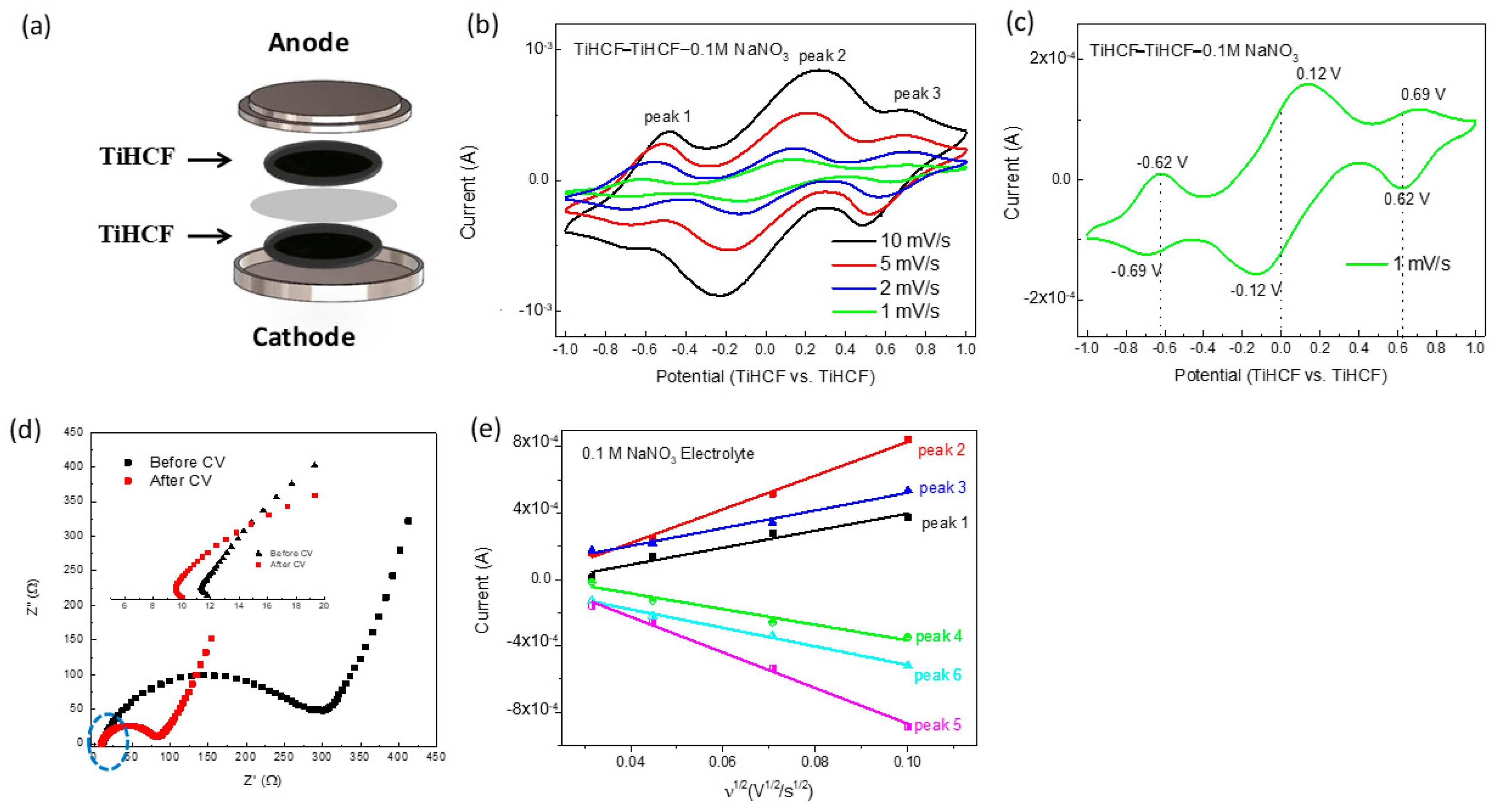
Due to the well-separated redox peaks of Fe3+/2+ and Ti4+/3+ redox couples, a full cell was assembled using TiHCF as both cathode and anode material, and the electrochemical performance of the symmetric Na-ion battery was tested in a 2032 coin cell with 0.1 M NaNO3 aqueous electrolyte, as shown in Figure 2a. In order to check the kinetic characteristic of the cell in that sandwich configuration, cyclic voltammetries were conducted in a potential range of −1–1V at first, and the results are shown in Figure 2b,c. When we applied a wide potential between the two electrodes, the redox peaks of Fe3+/Fe2+ and Ti4+/3+ can be observed at both sides of the electrode, and the voltametric peaks are symmetric around the zero point with respect to the current and potential. Based on the reports of Galus [30] and Kulesza [31], the voltametric currents are symmetric around 0 V, which indicate that the uniform distribution of the active material between two identical electrodes. Additionally, it also means that the material is stable, capable of carrying out the electrochemical reactions at the opposing electrodes continuously. Therefore, the proposed electrode material fulfills the key criterion for a symmetric use in both electrodes in a cell. Electrochemical impedance spectroscopy (EIS) data acquisition of the full cell before and after CV test were performed, as shown in Figure 2d. The intercept on the real impedance axis at a high frequency corresponds to the intrinsic resistance (Rs), which represents the resistance due to the electrolyte and electrode material, and the following semi-circle is ascribable to the charge-transfer resistance (Rct), which originates from the electronic and ionic resistance at the electrode–electrolyte interface and is easily influenced by the state of charge [32]. As observed after the CV test, the Rs and Rct values were both lower than that at the beginning, and the detailed fitting results and equivalent circuits are shown in Table S1. The decrease in Rct value may be due to the total discharge state of the electrode after the CV test [33]. However, the decrease in Rs value indicates that the intrinsic resistance was reduced after CV test, and this may be related to the progressive activation of the Ti-site inside the TiHCF structure during cycles, as previously reported in organic media [27].
Based on the Randles–Sevcik equation (Equation (1)), the relationship between the peak currents (Ip) and the square root of the scanning rate (v 1/2) are linear, and from the slope, the diffusion coefficient (DNa+) can be estimated,
Ip = 2.69 × 10⁵ n3/2 ADNa+1/2 CNa v1/2
where Ip, n, A, CNa, and v are the peak current, number of exchanged electrons per formula during the reaction (n = 1), effective reaction area (A = 0.502 cm2), Na+ concentration in the electrode, and scan rate, respectively. From Figure 2e and Table S2 data, we can see that, at scan rates of 1, 2, 5, and 10 mVs−1, the peak current has very good linear relationship with scan rate (v1/2), and this also indicates that the electrochemical reaction undergoes a diffusion-controlled process. The diffusion coefficients of DNa+ for anodic peaks 1–3 are 1.44 × 10⁻⁷ cm2/s, 5.59 × 10⁻⁷ cm2/s and 1.56 × 10⁻⁷ cm2/s, respectively. During the cathodic scan, DNa+ values for peaks 4–6 are 1.22 × 10⁻⁷ cm2/s, 6.27 × 10⁻⁷ cm2/s and 1.71 × 10⁻⁷ cm2/s, respectively. The diffusion coefficients for the anodic peaks and cathodic peaks are slightly different, which indicates that the redox process followed a quasi-reversible reaction rather than a totally reversible reaction [34].
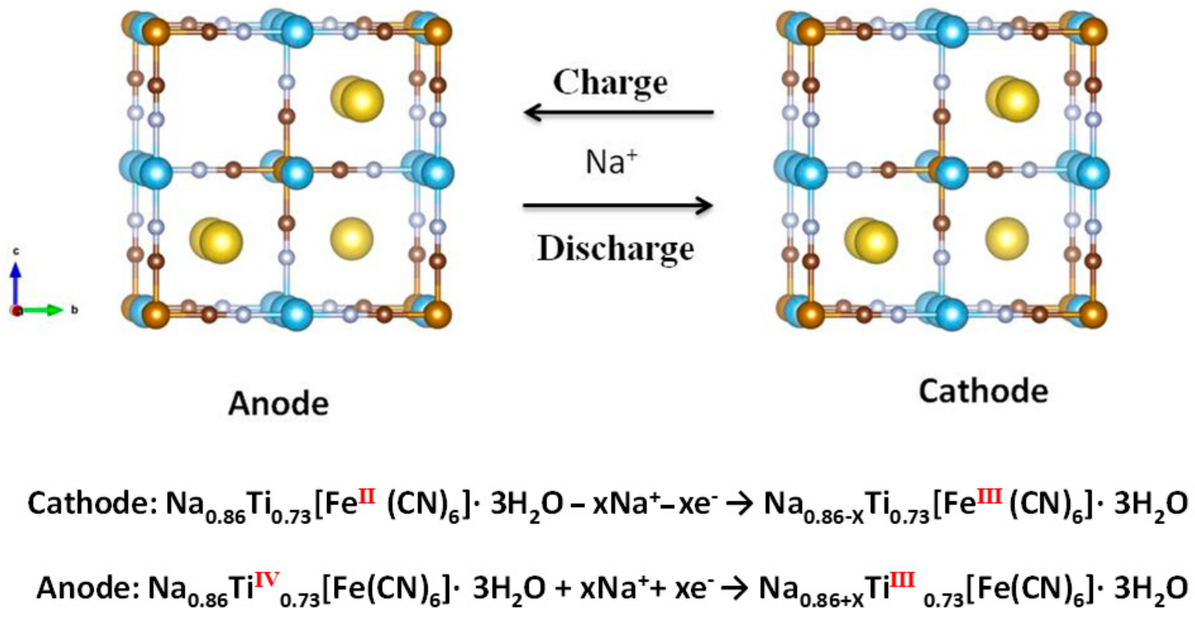
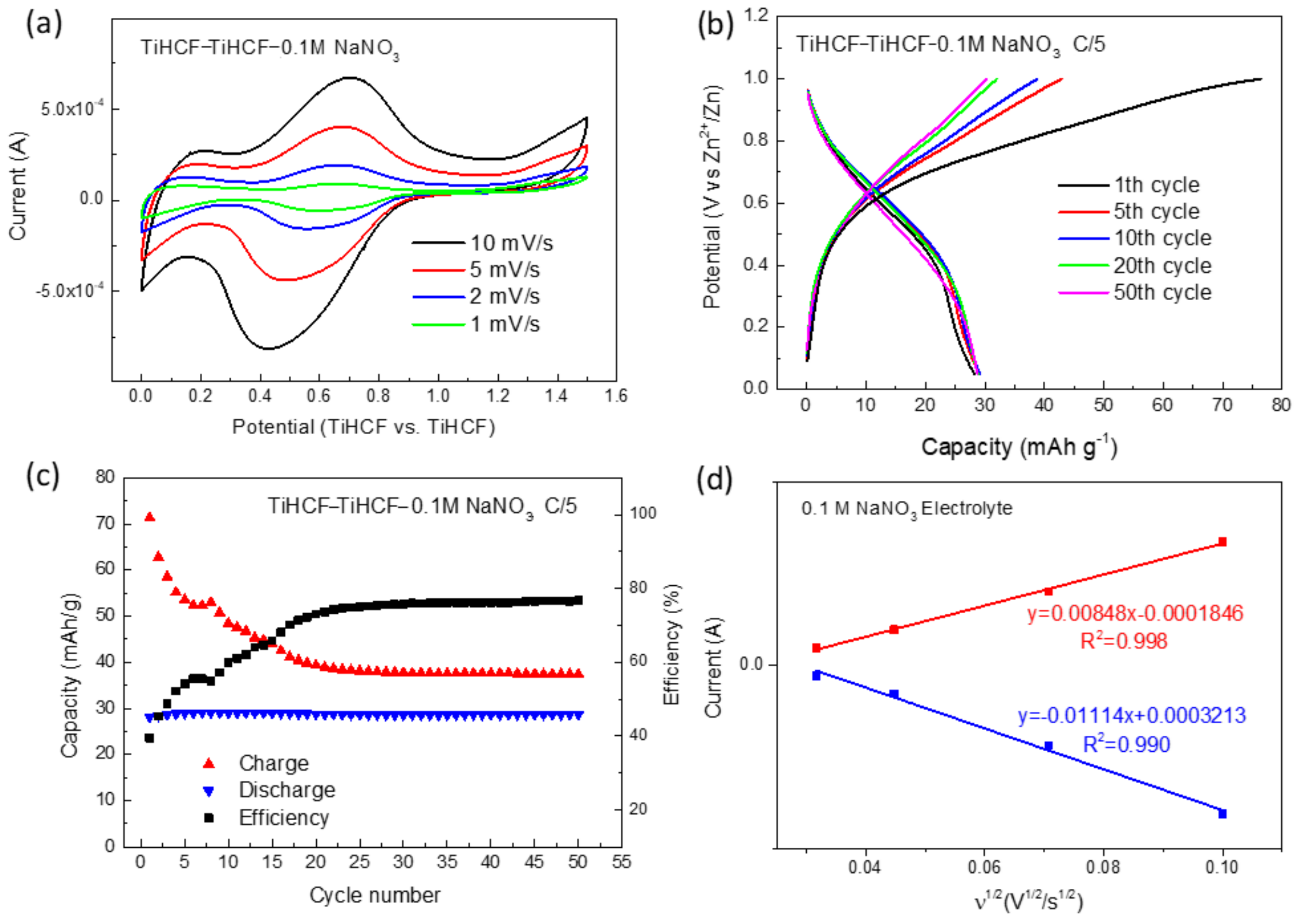
Secondly, the full battery displayed in Figure 2a was further tested in a positive potential only, within the voltage range of 0~1.5 V. The scheme of the aqueous full cell is shown in Figure 3. The anodic reaction is based on the extraction of Na-ions and accompanied with the redox of Fe3+/Fe2+ by formation of Na0.86-XTi0.73[Fe(CN)6]·3H2O, and the cathodic reaction is based on Ti4+/3+ redox couple with insertion of Na-ions into Na0.86Ti0.73[Fe(CN)6]·3H2O. Figure 4a shows the CV curves of the symmetric cell in 0.1 M NaNO3. There is one anodic peak and cathodic peak at approximately 0.60 V at 1 mV/s, which is consistent with the discharge plateau from the galvanostatic charge/discharge profiles (Figure 4b). As shown in Figure 4c, the discharge capacity was quite stable (around 30 mAhg−1), and no capacity fading was observed, even though the coulombic efficiency was low. The SEM images of pristine electrode, as well as electrodes (cathode and anode) after 50 cycles in 0.1 M NaNO3 electrolyte are shown in Figure S2. From the morphology, no obvious difference can be observed between pristine and cycled electrodes. From the semi-qualitative EDS result (Figure S3), the cycled electrodes have similar ratio atomic percentage of Ti, Fe, and Na. However, compared to the pristine electrode, the ratio of Ti/Fe increased during cycling, and this could be due to the extent of [Fe(CN)6]4− vacancies produced during cycling. Additional information can be gained from Figure 4d, where the current and scan rate (v 1/2) showed a very good linear relationship, and the diffusion constant calculated for oxidation and reduction peaks are 3.94 × 10⁻⁷ and 6.80 × 10⁻⁷ cm2/s (Figure 4d). These tests provided a proof-of-concept of the TiHCF system for the development of symmetric Na+ full batteries.
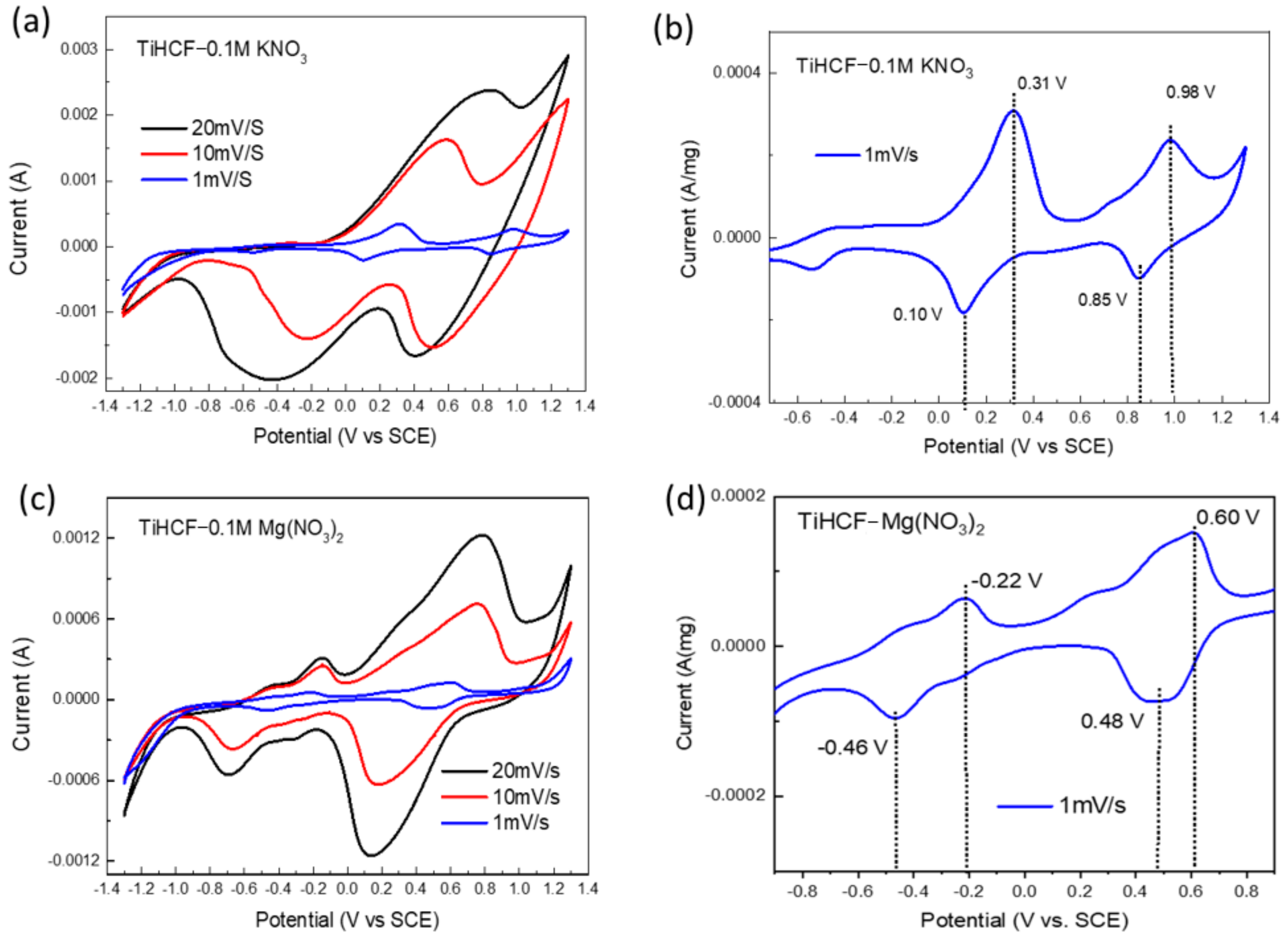
In addition to the aqueous NaNO3 electrolyte, the as-prepared electrode was also tested in 0.1 M KNO3 and 0.1 M Mg(NO3)2 solutions, and the CV curves recorded from the three-electrode system are shown in Figure 5. The CV curves in KNO3 electrolyte are very similar to those in the NaNO3 electrolyte. At a fast scan rate, the system underwent double reduction and oxidation, but only one oxidation peak around 0.6 V was observed. When we used a 1 mV/s scan rate, two pairs of well-separated redox peaks were found at voltage range around 0.31/0.10 V and 0.98/0.85 V, which are ascribed to the Ti4+/3+ and Fe3+/2+ pair of redox peaks. Figure 5c shows the CV curves of TiHCF in 0.1 M Mg(NO3)2 electrolyte; different from the CV curves in NaNO3 and KNO3 electrolyte, two redox peaks were observed even at the high scan rate, which indicated the better kinetic behavior of TiHCF for the Mg-ion battery. The redox potential of Fe3+/2+ and Ti4+/3+ pairs in the Mg-ion electrolyte are a little bit lower than those in the NaNO3 and KNO3 electrolytes, setting values around −0.22/−0.46 V and 0.60/0.48 V. Once again, two pairs of well-separated peaks suggest that K-ion and Mg-ion electrolyte can also be used for the symmetric batteries.
The full batteries of TiHCF, using 0.1 M KNO3 and 0.1 M Mg(NO3)2 as electrolyte, were assembled, and the electrochemical data are shown in Figure S4a,b. When we tested the full cell in potential range −1~1 V, there were also three pairs of redox peaks for both KNO3 and Mg(NO3)2 electrolytes that were symmetric with respect to the zero point. The calculations based on the current and scan rate for the six peaks are shown in Figure S4c,d and Table S3. We observed that all the diffusion coefficients of Na+, K+, and Mg2+ are almost of the same order of magnitude. It indicates that the three-dimensional ionic channels and interstices in the lattice of TiHCF are large enough for Na+, K+, and Mg2+ insertion and extraction.
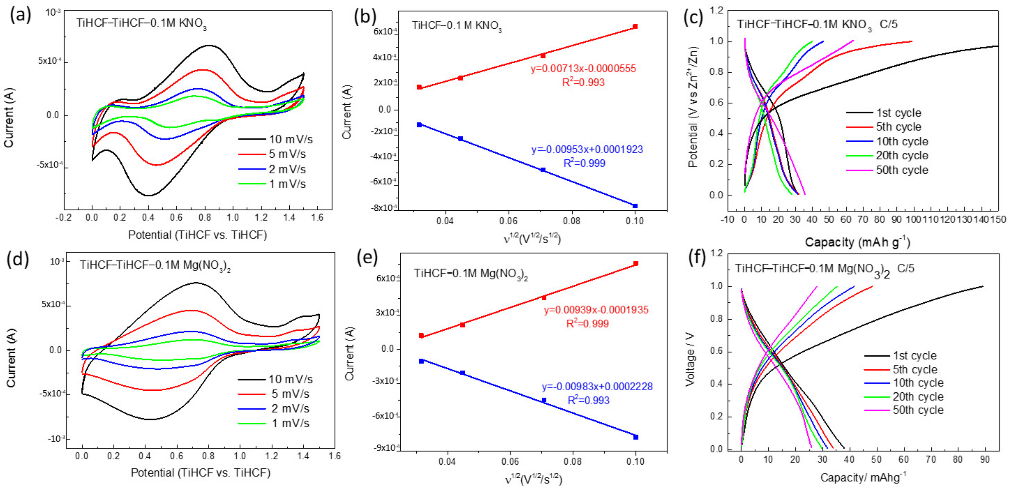
When we tested the full cell in potential range 0–1.5 V in 0.1 M KNO3 and 0.1 M Mg(NO3)2 electrolytes at the different scan rate, as shown in Figure 6a,c one pair of redox peaks was observed between 0.4–0.8 V at 10, 5, 2, 1 mV/s. The calculations based on the current and scan rate show good linear relationship (Figure 6b,e), and the diffusion constant for the oxidation/ reduction peaks are 2.78 × 10⁻⁷ cm2/s/ 4.97 × 10⁻⁷ cm2/s and 4.83 × 10⁻⁷ cm2/s/ 5.29 × 10⁻⁷ cm2/s in 0.1 M KNO3 and 0.1 M MgNO3 electrolytes, respectively.
The charge/discharge profiles of K+ and Mg2+ batteries are displayed in Figure 6c,f, and the curves display a potential plateau in 0.5–0.7 V range. The specific capacity of the Mg-ion battery was high at the beginning and then gradually decreased. However, the performance of Na-ion and K-ion full batteries was very similar, and the specific capacity even increased after cycling. Thus, even though the diffusion coefficients of Na+, K+, and Mg2+ are of the same order of magnitude, the TiHCF symmetric battery seems to have better stability in Na+ and K+ electrolytes.

3. Materials and Methods

3.1. Material Synthesis

The synthesis of TiHCF was based on a simple and reproducible method by mixing 50 mL 0.1 M tetrabutyl titanate (Sigma Aldrich, St. Louis, MO, USA) ethanol solution with 100 mL 0.1 M sodium ferrocyanide (Na4Fe(CN)6, Sigma Aldrich) aqueous solution containing 1.5 M HCl under continuous stirring to generate a precipitate, as reported in the article [27]. After mixing, the suspension was maintained at 60 °C for another 4 h under the N2 atmosphere and then aged for 4 days at room temperature. The obtained dark-green precipitate was centrifugated and washed with water and acetone and finally dried in a vacuum oven at 70 °C overnight.

3.2. Electrode Preparation and Electrochemical Tests

Electrode preparation: The electrode was prepared by mixing 70 wt% of active material, 25 wt% super C65 (IMERYS), and 5 wt% PTFE (polytetrafluoroethylene) and grinding the mixture until homogeneous thin solid pellet were obtained with mass density around 5~10 mg/cm2. The individual electrode was characterized in a three-electrode system in the aqueous electrolyte of NaNO3, KNO3, and Mg(NO3)2 (0.1 M) with a TiHCF pellet fixed with aluminum mesh as a working electrode, platinum wire as a counter electrode, and saturated calomel electrode (SCE, 0.244 V vs. SHE at 25 °C) as reference electrode. The symmetric cell with TiHCF pellets as the anode and cathode was assembled in a 2032 coin cell with a waterman glass fiber separator and NaNO3/ KNO3 /Mg(NO3)2 (0.1 M) electrolyte, and the specific capacity of the symmetric cell was calculated based on the weight of the cathode.
Cyclic voltammetry (CV) and Electrochemical impedance spectroscopy (EIS) were conducted on CHI 660 (CHInstrument, Inc., Bee Cave, TX, USA). The galvanostatic charge/discharge tests were performed at the room temperature in a battery testing system (MTI-Battery Analyzer).

3.3. Characterization

An FE-SEM LEO 1525 ZEISS instrument with an EDS detector was used for the morphology and the chemical compositions of the samples. The microscope was working with an acceleration voltage of 20 kV.

4. Conclusions

Symmetric full batteries of TiHCF in aqueous Na-ion/ K-ion/ Mg-ion electrolytes were studied. Due to the two well-separated redox peaks of Ti4+/3+ and Fe3+/2, a full battery with discharge capacity around 30 mAhg−1 and discharge plateau around 0.6 V was found to be possible for aqueous Na-ion/ K-ion/Mg-ion batteries. The calculations based on the current and scan rate showed that the diffusion constant of Na+, K+, and Mg2+ are almost of the same order of magnitude. It indicates that the three-dimensional ionic channels and interstices in the lattice of TiHCF are large enough for Na+, K+, and Mg2+ insertion and extraction. The advantage of aqueous symmetric batteries is a cost-effective and safe alternative solution for stationary energy storage, even considering the low intrinsic specific capacity these systems display.

Supplementary Materials

The following are available online at https://www.mdpi.com/article/10.3390/batteries8010001/s1, Figure S1: Electrochemical stability window of 0.1 M, 1 M and 10 M NaNO3 electrolytes on Al mesh electrode. (a) Overall electrochemical stability window; (b,c) magnified view of the regions outlined near anodic and cathodic extremes in figure (a). Table S1: EIS fitting result with equivalent circuit. Table S2: Diffusion coefficient as obtained by CV testing of TiHCF symmetric cell in 0.1M NaNO3 electrolyte, Figure S2. SEM images of (a,d) pristine electrode; (b,e) cathode and (c,f) anode after 50 cycles in 0.1 M NaNO3 electrolyte. Figure S3: EDS analysis of (a) pristine electrode; (b) cathode and (c) anode after 50 cycles in 0.1 M NaNO3 electrolyte; (d) EDS analysis result of atomic percentage of Ti, Fe, and Na. Figure S4: (a,b) Electrochemical performances of TiHCF full cell in 0.1 M KNO3 and 0.1 M Mg(NO3)2 electrolyte at potential range −1.0~1 V; (c,d) relationship between peak currents (Ip) and the square root of the scan rate (v1/2) in 0.1 M KNO3 and 0.1 M Mg(NO3)2 electrolyte. Table S3: Diffusion coefficient as obtained by CV testing of TiHCF symmetric cell in 0.1 M KNO3 and 0.1 M Mg (NO3)2 electrolyte.

Author Contributions

Conceptualization, M.L. and M.G.; methodology, M.L., M.M. and A.B.; investigation, M.L. and A.B.; writing—original draft preparation, M.L.; writing—review and editing, M.M. and M.G.; supervision, M.G. All authors have read and agreed to the published version of the manuscript.

Funding

This research was funded by the University of Bologna, RFO funding.

Institutional Review Board Statement

Not applicable.

Informed Consent Statement

Not applicable.

Data Availability Statement

Not applicable.

Acknowledgments

The authors thank G. Aquilanti and J. R. Plaisier for their support during the XAS and XRD data acquisition.

Conflicts of Interest

The authors declare no conflict of interest.

References

  1. Dunn, B.; Kamath, H.; Tarascon, J.-M. Electrical Energy Storage for the Grid: A Battery of Choices. Science 2011, 334, 928–935. [Google Scholar] [CrossRef] [Green Version]
  2. Mishra, A.; Mehta, A.; Basu, S.; Malode, S.J.; Shetti, N.P.; Shukla, S.S.; Nadagouda, M.N.; Aminabhavi, T.M. Electrode materials for lithium-ion batteries. Mater. Sci. Energy Technol. 2018, 1, 182–187. [Google Scholar] [CrossRef]
  3. Liu, B.; Zhang, J.G.; Xu, W. Advancing Lithium Metal Batteries. Joule 2018, 2, 833–845. [Google Scholar] [CrossRef] [Green Version]
  4. Hwang, J.Y.; Myung, S.T.; Sun, Y.K. Sodium-ion batteries: Present and future. Chem. Soc. Rev. 2017, 46, 3529–3614. [Google Scholar] [CrossRef] [Green Version]
  5. Delmas, C. Sodium and Sodium-Ion Batteries: 50 Years of Research. Adv. Energy Mater. 2018, 8, 1703137. [Google Scholar] [CrossRef]
  6. Eftekhari, A.; Jian, Z.; Ji, X. Potassium Secondary Batteries. ACS Appl. Mater. Interfaces 2017, 9, 4404–4419. [Google Scholar] [CrossRef] [PubMed]
  7. Hwang, J.Y.; Myung, S.T.; Sun, Y.K. Recent Progress in Rechargeable Potassium Batteries. Adv. Funct. Mater. 2018, 28, 1802938. [Google Scholar] [CrossRef]
  8. Rasul, S.; Suzuki, S.; Yamaguchi, S.; Miyayama, M. High capacity positive electrodes for secondary Mg-ion batteries. Electrochim. Acta 2012, 82, 243–249. [Google Scholar] [CrossRef]
  9. Aurbach, D.; Suresh, G.S.; Levi, E.; Mitelman, A.; Mizrahi, O.; Chusid, O.; Brunelli, M. Progress in rechargeable magnesium battery technology. Adv. Mater. 2007, 19, 4260–4267. [Google Scholar] [CrossRef]
  10. Zhang, L.; Dou, S.X.; Liu, H.K.; Huang, Y.H.; Hu, X.L. Symmetric electrodes for electrochemical energy-storage devices. Adv. Sci. 2016, 3, 1600115. [Google Scholar] [CrossRef] [Green Version]
  11. Kobayashi, E.; Plashnitsa, L.S.; Doi, T.; Okada, S.; Yamaki, J.I. Electrochemical properties of Li symmetric solid-state cell with NASICON-type solid electrolyte and electrodes. Electrochem. Commun. 2010, 12, 894–896. [Google Scholar] [CrossRef]
  12. Noguchi, Y.; Kobayashi, E.; Plashnitsa, L.S.; Okada, S.; Yamaki, J.I. Fabrication and performances of all solid-state symmetric sodium battery based on NASICON-related compounds. Electrochim. Acta 2013, 101, 59–65. [Google Scholar] [CrossRef]
  13. Plashnitsa, L.S.; Kobayashi, E.; Noguchi, Y.; Okada, S.; Yamaki, J. Performance of NASICON Symmetric Cell with Ionic Liquid Electrolyte. J. Electrochem. Soc. 2010, 157, A536. [Google Scholar] [CrossRef]
  14. Zhang, L.; Zhang, B.; Wang, C.; Dou, Y.; Zhang, Q.; Liu, Y.; Gao, H.; Al-Mamun, M.; Pang, W.K.; Guo, Z.; et al. Constructing the best symmetric full K-ion battery with the NASICON-type K3V2(PO4)3. Nano Energy 2019, 60, 432–439. [Google Scholar] [CrossRef]
  15. Kosova, N.V.; Osintsev, D.I.; Uvarov, N.F.; Devyatkina, E.T. Lithium Titanium Phosphate as Cathode, Anode and Electrolyte for Lithium Rechargeable Batteries. Chem. Sustain. Dev. 2005, 13, 253–260. [Google Scholar]
  16. Senguttuvan, P.; Rousse, G.; Arroyo, Y.; De Dompablo, M.E.; Vezin, H.; Tarascon, J.M.; Palacín, M.R. Low-potential sodium insertion in a nasicon-type structure through the Ti(III)/Ti(II) redox couple. J. Am. Chem. Soc. 2013, 135, 3897–3903. [Google Scholar] [CrossRef] [PubMed]
  17. Gao, H.; Goodenough, J.B. An Aqueous Symmetric Sodium-Ion Battery with NASICON-Structured Na3MnTi(PO4)3. Angew. Chem. 2016, 128, 12960–12964. [Google Scholar] [CrossRef]
  18. Zhou, Y.; Shao, X.; Lam, K.H.; Zheng, Y.; Zhao, L.; Wang, K.; Zhao, J.; Chen, F.; Hou, X. Symmetric Sodium-Ion Battery Based on Dual-Electron Reactions of NASICON-Structured Na3MnTi(PO4)3 Material. ACS Appl. Mater. Interfaces 2020, 12, 30328–30335. [Google Scholar] [CrossRef]
  19. Inoishi, A.; Nishio, A.; Yoshioka, Y.; Kitajou, A.; Okada, S. A single-phase all-solid-state lithium battery based on Li1.5Cr0.5Ti1.5(PO4)3 for high rate capability and low temperature operation. Chem. Commun. 2018, 54, 3178–3181. [Google Scholar] [CrossRef]
  20. Zhang, Q.; Liao, C.; Zhai, T.; Li, H. A High Rate 1.2V Aqueous Sodium-ion Battery Based on All NASICON Structured NaTi2(PO4)3 and Na3V2(PO4)3. Electrochim. Acta 2016, 196, 470–478. [Google Scholar] [CrossRef]
  21. Mullaliu, A.; Asenbauer, J.; Aquilanti, G.; Passerini, S.; Giorgetti, M. Highlighting the Reversible Manganese Electroactivity in Na-Rich Manganese Hexacyanoferrate Material for Li- and Na-Ion Storage. Small Methods 2020, 4, 1900529. [Google Scholar] [CrossRef] [Green Version]
  22. Mullaliu, A.; Gaboardi, M.; Plaisier, J.R.; Passerini, S.; Giorgetti, M. Lattice Compensation to Jahn-Teller Distortion in Na-Rich Manganese Hexacyanoferrate for Li-Ion Storage: An Operando Study. ACS Appl. Energy Mater. 2020, 3, 5728–5733. [Google Scholar] [CrossRef]
  23. Neff, V.D. Some Performance Characteristics of a Prussian Blue Battery. J. Electrochem. Soc. 1985, 132, 1382–1384. [Google Scholar] [CrossRef]
  24. Zhang, J.; Zhang, D.; Niu, F.; Li, X.; Wang, C.; Yang, J. FeFe(CN)6 Nanocubes as a Bipolar Electrode Material in Aqueous Symmetric Sodium-Ion Batteries. Chempluschem 2017, 82, 1170–1173. [Google Scholar] [CrossRef] [PubMed]
  25. Guo, S.; Yu, H.; Liu, P.; Ren, Y.; Zhang, T.; Chen, M.; Ishida, M.; Zhou, H. High-performance symmetric sodium-ion batteries using a new, bipolar O3-type material, Na0.8Ni0.4Ti0.6O2. Energy Environ. Sci. 2015, 8, 1237–1244. [Google Scholar] [CrossRef] [Green Version]
  26. Guo, S.; Liu, P.; Sun, Y.; Zhu, K.; Yi, J.; Chen, M.; Ishida, M.; Zhou, H. A High-Voltage and Ultralong-Life Sodium Full Cell for Stationary Energy Storage. Angew. Chem.-Int. Ed. 2015, 54, 11701–11705. [Google Scholar] [CrossRef] [PubMed]
  27. Li, M.; Mullaliu, A.; Passerini, S.; Giorgetti, M. Titanium activation in prussian blue based electrodes for na-ion batteries: A synthesis and electrochemical study. Batteries 2021, 7, 5. [Google Scholar] [CrossRef]
  28. Paulitsch, B.; Yun, J.; Bandarenka, A.S. Electrodeposited Na2VOx[Fe(CN)6] films As a Cathode Material for Aqueous Na-Ion Batteries. ACS Appl. Mater. Interfaces 2017, 9, 8107–8112. [Google Scholar] [CrossRef]
  29. Luo, Y.; Shen, B.; Guo, B.; Hu, L.; Xu, Q.; Zhan, R.; Zhang, Y.; Bao, S.; Xu, M. Potassium titanium hexacyanoferrate as a cathode material for potassium-ion batteries. J. Phys. Chem. Solids 2018, 122, 31–35. [Google Scholar] [CrossRef]
  30. Makowski, O.; Stroka, J.; Kulesza, P.J.; Malik, M.A.; Galus, Z. Electrochemical identity of copper hexacyanoferrate in the solid-state: Evidence for the presence and redox activity of both iron and copper ionic sites. J. Electroanal. Chem. 2002, 532, 157–164. [Google Scholar] [CrossRef]
  31. Kulesza, P.J. Solid-state electrochemistry of iron hexacyanoferrate (Prussian Blue type) powders Evidence for redox transitions in mixed-valence ionically conducting microstructures. J. Electroanal. Chem. Interfacial Electrochem. 1990, 289, 103–116. [Google Scholar] [CrossRef]
  32. Hou, Z.; Zhang, X.; Li, X.; Zhu, Y.; Liang, J.; Qian, Y. Surfactant widens the electrochemical window of an aqueous electrolyte for better rechargeable aqueous sodium/zinc battery. J. Mater. Chem. A 2017, 5, 730–738. [Google Scholar] [CrossRef]
  33. Scavetta, E.; Tonelli, D.; Giorgetti, M.; Nobili, F.; Marassi, R.; Berrettoni, M. AC impedance study of a synthetic hydrotalcite-like compound modified electrode in aqueous solution. Electrochim. Acta 2003, 48, 1347–1355. [Google Scholar] [CrossRef]
  34. Shoparwe, N.F.; Makhtar, M.M.Z.; Sata, S.A.; Kew, W.S.; Mohamad, M.; Shukor, H. Cyclic voltammetry studies of bioanode microbial fuel fells from batch culture of Geobacter sulfurreducens. IOP Conf. Ser. Earth Environ. Sci. 2021, 765, 012102. [Google Scholar] [CrossRef]
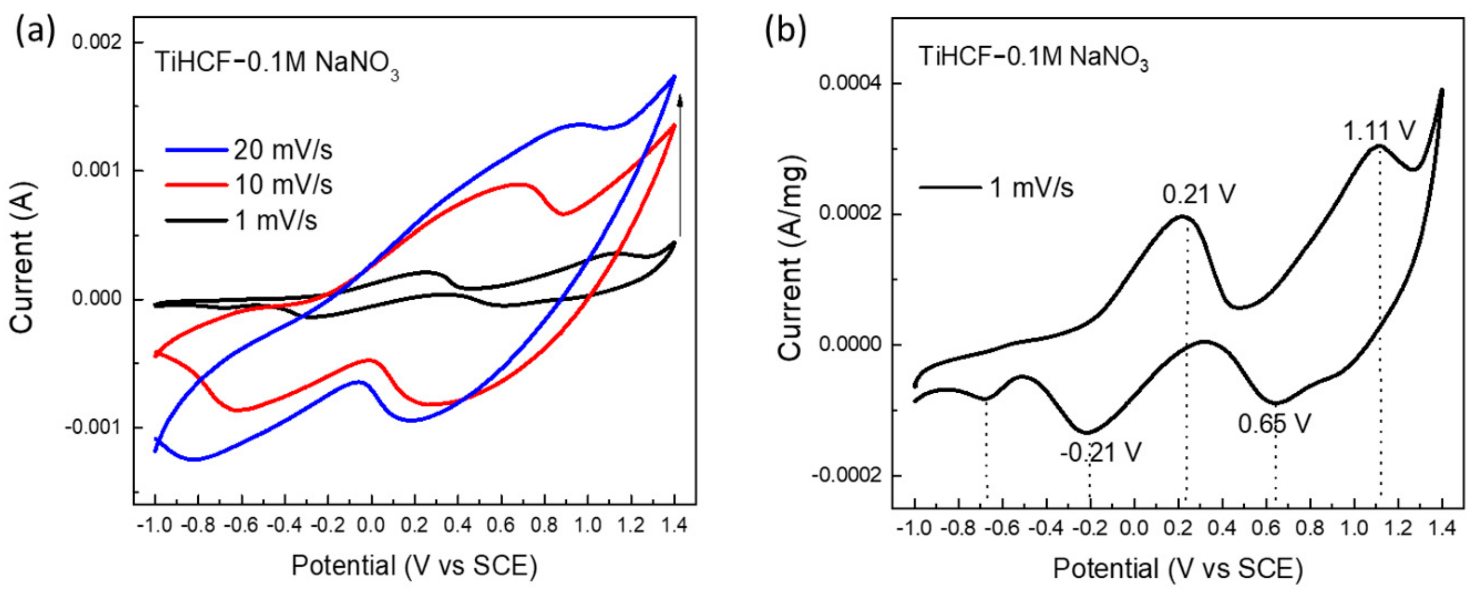
Figure 1. Three-electrode system: (a) CV curves of TiHCF in 0.1 M NaNO3 electrolyte at different scan rate; (b) CV curves of TiHCF at 1 mVs−1, using mass normalized current.
Batteries 08 00001 g001
Figure 2. Electrochemical performances of the full cell using TiHCF pellet as both cathode and anode material at the potential range −1.0~1 V: (a) schematic diagram of TiHCF full cell; (b) CV curves at different scan rate; (c) CV curve at 1 mV/s; (d) EIS analysis of the full cell before and after CV test; (e) relationship between the peak currents (Ip) and the square root of the scan rate (v1/2).
Batteries 08 00001 g002
Figure 3. Schematic illustration of the aqueous symmetric sodium-ion battery with TiHCF as the anode and the cathode.
Batteries 08 00001 g003
Figure 4. Electrochemical performances of the full cell using TiHCF pellet as both the cathode and anode material at the potential range 0~1.5 V in 0.1 M NaNO3 electrolyte. (a) CV curves at different scan rate; (b) Galvanostatic charge–discharge profiles at C/5; (c) cycling performance of the full cell at C/5; (d) relationship between the peak currents (Ip) and scanning rate (v1/2).
Batteries 08 00001 g004
Figure 5. Three-electrode system: (a,c) CV curves of TiHCF in 0.1 M KNO3 and 0.1 M Mg(NO3)2 electrolyte at the different scan rate; (b,d) CV curves of TiHCF in 0.1 M KNO3 and 0.1 M Mg(NO3)2 at 1 mVs−1, using mass normalized current.
Batteries 08 00001 g005
Figure 6. (a,d) Cyclic voltammetry of TiHCF full cell in 0.1 M KNO3 and 0.1 M Mg(NO3)2 electrolytes at potential range 0~1.5 V; (b,e) relationship between the peak currents (Ip) and the square root of the scan rate (v1/2) in 0.1 M KNO3 and 0.1 M Mg(NO3)2 electrolyte; (c,f) Galvanostatic charge–discharge profiles of TiHCF symmetric batteries in 0.1 M KNO3 and 0.1 M Mg(NO3)2 electrolyte at C/5.
Batteries 08 00001 g006
Publisher’s Note: MDPI stays neutral with regard to jurisdictional claims in published maps and institutional affiliations.