Abstract
Along with the soaring demands for all-solid-state thin-film lithium-ion batteries, the problem of their energy density rise becomes very acute. The solution to this problem can be found in development of 3D batteries. The present work deals with the development of a technology for a 3D solid-state lithium-ion battery (3D SSLIB) manufacturing by plasma-chemical etching and magnetron sputtering technique. The results on testing of experimental samples of 3D SSLIB are presented. It was found that submicron-scale steps appearing on the surface of a 3D structure formed on Si substrate by the Bosch process radically change the crystal structure of the upper functional layers. Such changes can lead to disruption of the layers’ continuity, especially that of the down conductors. It is shown that surface polishing by liquid etching of the SiO2 layer and silicon reoxidation leads to surface smoothing, the replacement of the dendrite structure of functional layers by a block structure, and a significant improvement in the capacitive characteristics of the battery.
1. Introduction
The demand for all-solid-state thin-film lithium-ion batteries (SSLIB) [1,2,3,4,5,6] has grown significantly in the last decade. The area of their widest application is smartphones (~25% of all SSLIBs), wrist gadgets (~30%) and transdermal patches (~25%), while SSLIB for power banks, RFID tags and smart cards is less than 10% from their total volume [7]. According to a report from IDTechEx, the market for solid-state thin-film lithium-ion batteries will grow from $22 million to $109 million from 2020 to 2025. SSLIBs would be even more in demand if not for their small specific capacity. Unfortunately, a decrease in battery size is accompanied by a decrease in the density of stored energy. For instance, Cymbet Corporation produces all-solid-state batteries with nominal capacity 50 μA∙h (sizing 5.7 × 6.1 × 0.2 mm), and 5 μA∙h (sizing 1.75 × 2.15 × 0.2 mm). The energy density of these batteries amounts to 25 and 27 W∙h/L, while for lithium-ion batteries of normal capacity (A∙h units), this value is 200–400 W∙h/L [8].
Currently, the most promising way to increase the specific capacity of SSLIB is to develop 3D batteries. The goal of 3D design is increasing the volumetric energy density of the batteries by enhancement of their specific surface area. Indeed, a planar solid-state design depicted in Figure 1 shows that relatively much of the space is occupied by inactive materials such as substrate, capsulation materials and packaging. The 3D design allows obtaining much higher energy storage with almost the same amount of packaging and substrate material. The internal surface area between electrodes and electrolyte in 3D batteries is higher, therefore a much higher total battery current can be obtained [9,10]. Market demand for smartphones and wearable devices including implantable medical devices, drug delivery systems, microsensors and so on opened a special niche for 3D batteries with typical size from 1 to 10 mm3 and power from 10 nW to 1 mW [1,2,3,4,5,6,7].

Figure 1.
Cross-section of solid-state thin-film lithium-ion battery.
Despite the obvious advantages of 3D SSLIB, they also have certain shortcomings. The main one is the uneven deposition of the functional layers of the battery. First of all, this refers to batteries with a high aspect ratio—the ratio of the relief height to its characteristic lateral size [11]. The inhomogeneity in the thickness of the functional layers leads to the fact that different sections of SSLIB operate in different regimes, and where the current density is higher, the specific capacity is lower. The difference in the thickness of the functional layers is observed on surfaces with different slope angles of the relief. In addition to this, the surface irregularities related to the manufacturing technology may occur. For example, the truncated cones considered in this work contain steps (scallops) on the sidewall of the cones, which appear in the course of alternation of etching and passivation stages during the Bosch process [12]. As shown below, functional layers, which on a smooth surface have a large-block structure, when deposited on these steps, can form island-type structures with cavities. The formation of cavities and the difference in morphology of the same layer deposited on the conical and on the flat surface leads to a violation of continuity of a functional layer and even complete isolation of the cone.
Below is a description of the manufacturing technology of 3D SSLIB of LiCoO2-LiPON-SiOAL electrochemical system and the results of testing its charge–discharge characteristics. It is shown that the smoothing of steps on the surface of truncated cones leads to the formation of films with a large-block structure and an increase in the contribution of the cones to the SSLIB capacity.
2. Experimental Procedure
2.1. Batteries Manufacturing
In studying the effect of the silicon substrate profile on the capacitive properties of 3D SSLIB the batteries of an electrochemical system LiCoO2-LiPON-SiOAl were manufactured. A silicon wafer with a 3D relief formed by a truncated cones array served as a substrate for the deposition of functional layers. The conical array was created by a modified Bosch process based on silicon etching through a mask in the form of disks with a rounded profile [13]. The method allows transfer of the mask pattern to silicon surface by its plasma-chemical etching with simultaneous adjusting of the silicon and photoresist etching selectivity. For this purpose, the basic Bosch process was supplemented by the step of photoresist etching in an oxygen-containing plasma. The shape of the conical structures was controlled by the duration of the additional step and by selection of silicon etching conditions.
To form 3D relief on silicon wafer surface Plasmalab System 100 (Oxford Instruments, Tatton, UK) with an inductively coupled plasma source (ICP 360) was used. A mask on the surface of the silicon wafer was formed by photoresist S1318 SP15 spin-coating followed by its exposure to ultraviolet radiation and etching. Before the start of the Bosch process the mask was kept melted at 145 °C for 20 min to shape its elements to a form of spherical lens [14]. Such shape allows a stepwise lens diameter reduction in a course of etching process to obtain 3D structures of a tapered profile.
Truncated silicon cones obtained as a result of plasma-chemical etching had a characteristic stepped surface. The number of steps corresponds to the number of etch-passivation cycles in the Bosch process. After plasma-chemical etching, the silicon substrate was oxidized in a SDOM-3/100-M1 thermal diffusion facility (GKMP Research & Production Company LLC, Bryansk, Russia) with a quartz tube reactor 150 mm in diameter. The reactor temperature in the working area was 1080 ± 1 °C. After reaching a predetermined temperature, silicon wafers in a special quartz boat-stand were placed in the working zone of the reactor and held for 5 min. After heating the plates and the boat, dry oxygen of 99.7% purity was fed into the reactor; the gas flow rate was 300 L/h (500 sccm). The first 10 min the plates were oxidized in dry oxygen, then the oxidation was carried out in a vapor–gas mixture for 4 h and the last 10 min in dry oxygen. To generate water vapor, a standard evaporation system was used; the flow rate of distilled water was 500 mL/h. The thickness of the resulting oxide layer was ~0.9 μm.
Then, one of the substrates (SSLIB-1) was used for functional layers deposition without additional treatment. The second (SSLIB-2) was subjected to SiO2 etching in a solution of HF:H2O 5:1 until complete removal of the oxide, and then re-oxidized under the same conditions. As a result, 3D structures in the form of rows of truncated cones with a base diameter of 10–12 µm, height about 3.5 µm and a period of 15 µm were obtained (Figure 2).
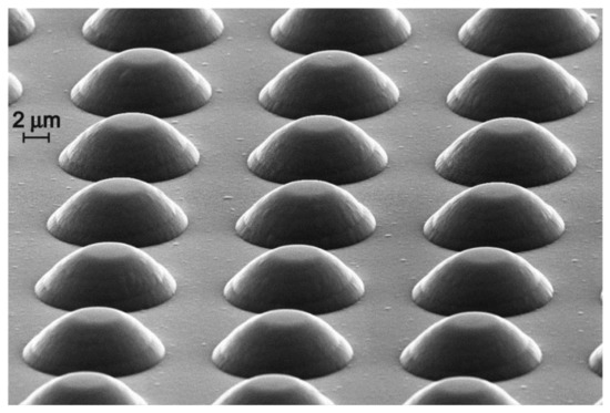
Figure 2.
SEM image of the 3D SSLIB structure.
The functional layers of the battery were successively deposited on the oxidized 3D substrate surface by RF magnetron sputtering of Ti, LiCoO2, Li3PO4, Si0.9Al0.1 and Ti targets at an SCR 651 Tetra (Alcatel, Paris, France) system. This system is equipped with four magnetrons, so during SSLIB fabrication replacement of targets is not required. This significantly reduces the time that the lithium-containing functional layers are exposed to the atmosphere. The system is equipped with a heating device for the substrate temperature regulating. The copper substrate holder is heated from the blackened profiled rear side by radiation from an electric furnace made of an Inconel electric heating tube element (Thermocoax, Paris, France). Furnace power (100 W) allows heating a standard silicon wafer up to 550 °C, and a mask holder to 450 °C. The temperature is measured with a platinum thermal sensor installed in the furnace using a Type 810 controller (Eurotherm, Worthing, UK). The substrate heating was used during the deposition of lithium cobaltite to obtain a layer with crystalline structure.
The LiCoO2, Li3PO4, and Si0.9Al0.1 targets of 99.99% purity and 100 mm in diameter were made of original powders by hot-pressing technique at a temperature of 700 °C (GIRMET Ltd., Moscow, Russia). Before depositing, the sputtering system SCR 651 Tetra was evacuated to residual pressure 1 × 10⁻⁶ Pa. The layers were deposited in the following sequence: Ti—lower current collector, LiCoO2—cathode layer, LiPON—solid electrolyte, Si-O-Al—anode layer, Ti—upper current collector. Functional layers were deposited through metal masks of different window sizes varying from 18 mm × 17 mm for the lower current collector to 10 mm × 10 mm for the upper current collector. The basic parameters of the layers’ deposition process are given in Table 1.

Table 1.
Parameters of technological processes for the manufacture 3D SSLIB.
2.2. Methods of Characterization
The surface morphology and the structure of the cross sections of the batteries before and after the electrochemical testing were investigated on a scanning electron microscope Supra-40 (Carl Zeiss, Oberkochen, Germany). Elemental analysis of functional layers was carried out by energy-dispersive X-ray microanalysis (EDXMA) on INCAx-acta (Oxford Instruments, Abingdon, UK) and by Auger spectroscopy with a PHI-660 spectrometer (PerkinElmer, Waltham, MA, USA). Since both methods are insensitive to lithium, LiCoO2 energy-dispersive microanalysis was supplemented by X-ray phase analysis, performed on an ARL X’tra X-ray diffractometer (Thermo Fisher Scientific, Switzerland). The study of the elemental composition was performed using test structures or so-called «bystanders», which consist of the same functional layers deposited on a flat silicon wafer placed nearby a 3D silicon substrate. After electrochemical tests, 3D SSLIB chip mapping was accomplished to visualize the distribution of chemical elements.
The electrochemical testing of batteries was carried out by the method of galvanostatic cycling with a multichannel potentiostat-galvanostat P-20x8 (Electrochemical Instruments, Chernogolovka, Moscow Region, Russia). The tests of the 3D SSLB-1 were performed according to the following scheme: 1–5 cycles—current 5 μA, charging time 1 h; 6–10 cycles—current 5 μA, charging time 1 h; 11–15 cycles—current 5 μA, charging time 2 h; 16–20 cycles—current 15 μA, charging time 1 h; 21–23 cycles—current 35 μA, charge up to 4.0 V, discharge to 2 V; 24–30 cycles—current 35 μA, charge up to 4.5 V, discharge to 2 V.
Tests for the 3D SSLIB-2 sample proceeded in similar regimes: 1–5 cycles—current 5 μA, charging time 10 min from 0 to 2.5 V; 6–10 cycles—current 5 μA, charging time 1 h from 0 to 3 V; 11–15 cycles—current 5 μA, charging time 2 h; 16–20 cycles—current 15 μA, charging time 1 h or up to 3.3 V, discharge to 0 V; 21–25 cycles—current 35 μA, charging time 1 h or up to 3.6 V, discharge to 0 V; 26–30 cycles—current 35 μA, charging for 2 h or up to 4 V, discharge to 2 V; 31–35 cycles—current 70 μA, charge up to 4 V, discharge to 2 V.
2.3. Morphology and Elemental Composition of Functional Layers
The study of 3D SSLIB-1 and 3D SSLIB-2 morphology by electron microscopy has revealed significant differences in the structure of their functional layers. First of all, this refers to the LiCoO2 layer, the structure of which is most strongly affected by the roughness of the silicon substrate. This, as will be shown below, is the main reason for the different capacity and stability of the 3D SSLIB-1 and 3D SSLIB-2 batteries.
Microanalysis of the test layers was performed twice: immediately after application and after a month of storage in the atmosphere. The measurements were carried out at a minimum accelerating voltage of 6 kV (to exclude the signal from the SiO2 layer), an aperture of 120 μm, and a magnification of ×2000. The results of the analysis are presented in Table 2. Since the method is not sensitive to lithium, the content of all other elements of the lithium-containing layers was taken as 100%. As for Si-O-Al the repeated measurements of the elemental composition were not performed, as this material is rather stable, and its composition practically does not change in one month.

Table 2.
Results of microanalysis of test layers just after deposition and after a month storage in the atmosphere.
According to EDXMA data (Table 2), the stoichiometric composition of the freshly deposited lithium cobaltite film is LiCoO1.79. At the same time, according to X-ray phase analysis data, the crystalline phase has a stoichiometric composition LiCoO2. The discrepancy in the oxygen content in these data is explained by the low accelerating voltage of the electron beam. It is known that the EDXMA method gives the most accurate data at a voltage of 10–11 keV. The dependence of the measurement error of the elemental composition on the energy of the electron beam and the procedure for calculating the correction factors are given in [15]. The stoichiometric composition of the solid electrolyte (according to Table 2 data) is Li3PO2.52N0.44, which is close to the data of [16], where, using EDXMA and inductively coupled plasma, the composition of the sputtered LiPON film was determined as Li2.99PO3.38N0.41.
The elemental composition of the negative electrode is in the range of values that provide a capacity within 1000–1500 mA·h/g [17]. As Si/Al ratio in the target was 3 while in the Si-O-Al film this ratio is 3.2, the error of the estimation of this element’s concentration in the Si-O-Al nanocomposite is insignificant. Oxygen data may be somewhat underestimated for the reasons indicated above. Noteworthy is the presence of a rather large amount of Ar in Si-O-Al. On the one hand, Ar atoms “loosen up” Si-O-Al structure and rise Li diffusivity. On the other hand, during lithiation–delithiation argon can predominantly diffuse in one direction and collect in gas bubbles, forming cavities inside or between the battery layers.
2.4. X-ray Phase Analysis of Positive Electrode and Solid Electrolyte
Since energy-dispersive microanalysis is insensitive to lithium, the layers of lithium cobaltite and LiPON were characterized by X-ray phase analysis. In this case, a double goal was pursued: (i) to show that the stoichiometric composition of lithium cobaltite (at least that of its crystalline phase LCO) is retained during magnetron deposition; and (ii) to make sure that the solid electrolyte is amorphous and remains so despite heating caused by subsequent layers deposition. For this, four test samples were made by depositing LiCoO2 and LiCoO2/LiPON on titanium foil. Two of them were annealed at a temperature of 500 °C in an argon. Diffraction patterns of all samples both annealed and without annealing are compared in Figure 3. No crystallized LiPON phase was found. Thus, annealing of LiPON films up to 500 °C in an inert medium does not cause their crystallization.
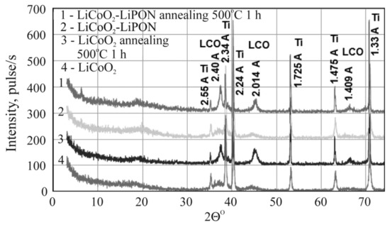
Figure 3.
Diffraction patterns of annealed and unannealed structures Ti/LiCoO2 (LCO) and Ti/LiCoO2/LiPON. Annealing conditions are shown in the plot.
3. Results and Discussion
3.1. The Electrochemical Behavior of 3D SSLIBs
Figure 4 shows the results of electrochemical testing of 3D SSLIB-1 and 3D SSLIB-2 by the method of galvanostatic cycling. The current-producing reactions in lithium-ion batteries LiCoO2-LiPON-SiOAl are commonly known. The charging of a negative electrode is lithium insertion into the electrode material. In the case under consideration, it is xLi+ + xe + Si → LixSi. The charging of a positive electrode is lithium extraction or LiCoO2 → Li1−xCoO2 + xLi+ + xe. The discharging reaction occurs in the opposite direction. The voltage peaks for both reactions, shown in Figure 4b, are well-known as well.
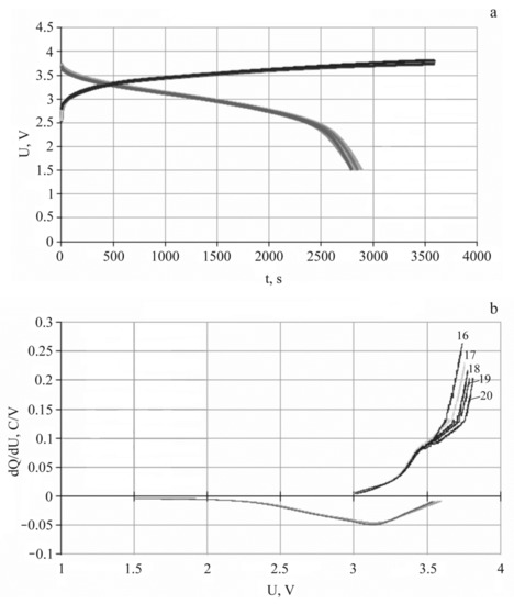
Figure 4.
Charging–discharge characteristics of 3D SSLIB-2 (a) and its differential capacity (b) for 16th–20th cycles, current 15 μA.
The main goal of cycling was to estimate the rate of battery degradation, which is defined as the decrease in the discharge capacity over a certain number of cycles. A 10% decrease in capacity per 1000 cycles is considered to be a good stability indicator for SSLIB. Cycling results are usually presented in the form of C(n) plots, where C is the specific capacity and n is the cycle number. In this case the bias or systematic error of the capacity measuring is not of particular importance. As for the dispersion of experimental points, in a view of battery degradation from cycle to cycle, i.e., the lack of reproducibility of the experimental conditions, its calculation makes little sense. For this reason, statistical processing of the cycling results is never used and the confidence intervals on the C(n) plots are not indicated.
Figure 5 shows the cycling plots of 3D SSLIB-1,2 for the first 35 charge–discharge cycles. The test modes are given in Table 3. The discharge capacity and Coulombic efficiency are also indicated in the Table 3. For thin films ~2 μm thick the determination of porosity is a difficult task. For example, the mass of the active substance of the test electrode with the maximum filling of the flask is at the sensitivity limit of an adsorption porosimeter (Surfer, Thermo Scientific), used in present work. This makes the calculation of the specific capacity almost senseless. That is why in Table 3 the capacity values are given in ampere-hours per unit surface. As the battery is of a pyramidal shape with a base of 1.6 × 1.6 cm2 (bottom electrode) and apex of 1.0 × 1.0 cm2 (upper down conductor), its area was assumed to be equal to that of the electrolyte S = 1.96 cm2.
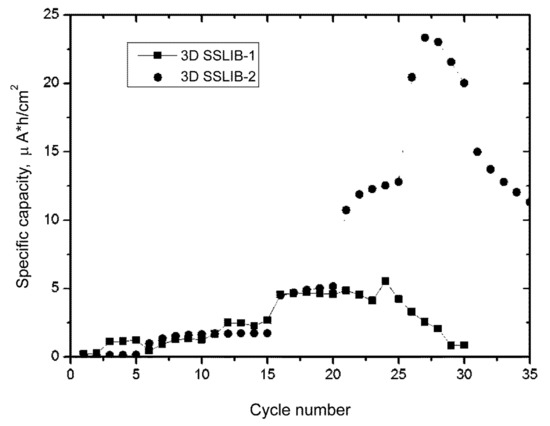
Figure 5.
Cycling plots of experimental 3D SSLIBs. 3D SSLIB-1 (squares) was made without surface smoothing. 3D SSLIB-2 (circles) was subjected to chemical polishing.

Table 3.
Batteries’ cycling modes and capacitive characteristics.
The first cycles in Figure 5 are characterized by the absence of a regular dependence of the discharge capacity on the C-rate, since the charge currents are minor and the full charge of the battery in a fixed time is not achieved (Table 3). In addition, during the first cycles, the processes of silicon reduction from silicon dioxide takes place in the anode, which leads to a real increase in the anode capacity. The dependence of the capacity on the charge rate appears only at later cycles, for example, for 3D SSLIB-1 starting from the 25th cycle, and for 3D SSLIB-2 at 28th one (Figure 5).
A comparison of cycling plots of 3D SSLIB-1,2 shows that up to the 21st cycle at a current of 15 μA, the capacities of the batteries are similar and repeat each other with small deviations. Furthermore, the capacitive characteristics differ sharply from each other. The battery with a smoothed profile of the silicon substrate (3D SSLIB-2) shows a significant increase in capacity by 2.5 times at a current of 35 μA in a potential window of 0–3.6 V, while the 3D SSLIB-1 sample practically does not change the capacity at an increase in the current up to 35 μA and an expansion of the potential window to 4.0 V.
It should be noted that an increase in the charge current and an expansion of the potential window results in a sharp drop in the discharge capacity for both samples, what indicates irreversible processes of lithium transfer in battery layers [18]. There are known specifics of LiCoO2 as functional material of positive electrodes: the higher the cut-off voltage is when charging, the higher the charge capacity and simultaneously the higher the tendency of irreversible structure transformation. The experiment with increased charge voltage from 4.0 to 4.5 V after the 24th cycle was aimed to perform a quantitative evaluation of this phenomenon in terms of the Coulombic efficiency. The Coulombic efficiency can be determined only for charging processes limited by the upper value of the potential window as the ratio of the discharge time in a given potential window to the charge time × 100%. As can be seen from Table 3, at a current of 35 μA, a noticeable decrease in the Coulombic efficiency of both batteries is observed, while the efficiency of the 3D SSLIB-1 decreases faster than the SSLIB-2. This means that in addition to irreversible reactions in lithium cobaltite, irreversible processes also occur in other elements of 3D SSLIB-1. The nature of these processes will be discussed below.
3.2. Effect of 3D Substrate Relief on SSLIB Functional Layers Morphology
After electrochemical tests, 3D SSLIB samples were examined on a SEM Supra 40 to determine the possible reasons for the different behavior in their capacity during cycling. Several factors can influence the behavior of 3D SSLIB cycling curves. One of them, obviously, is the discontinuity of functional layers on the truncated cone of a 3D structure. Figure 6a,b shows SEM images of the 3D SSLIB-1 chip with a stepped surface profile and that of 3D SSLIB-2 with a smoothed profile.
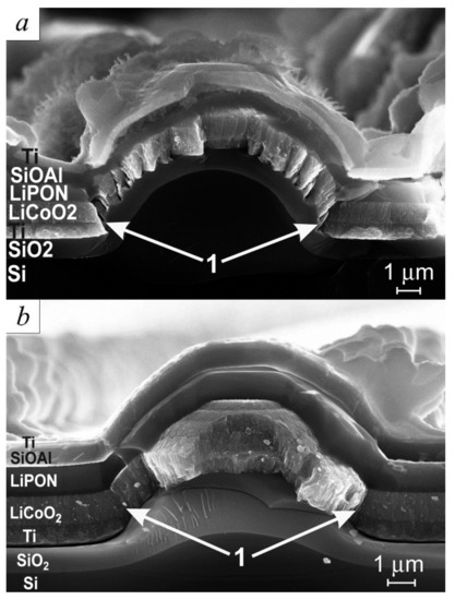
Figure 6.
SEM image of the batteries’ cleavages: (a) 3D SSLIB-1 without smoothing of the etching profile; (b) 3D SSLIB-2 on a smoothed silicon substrate.
Figure 6a illustrates how faintly discernible steps on a silicon cone in a course of thermal oxidation transform into a system of concentric terraces, on which all subsequent functional layers are growing by a mechanism similar to island-type films growth [19]. It can be clearly seen in the figure that the lower terrace of the layer (region 1) forms shoulders at the very base of the cone, which screen the base of the cone from the deposition of titanium, creating a break in the down conductor film. Exactly the same discontinuities in the down conductor film are formed on the overlying terraces, because the Ti film there has an island-type structure with cavities at the base of the islands. Thus, the electrical contact between the steps is either absent altogether or is carried out over nanometer Ti jumpers. All this makes the lower titanium down conductor of 3D SSLIB-1 sensitive to the current density. Even at minimal currents, the local current density can reach high values and lead to the destruction of the jumpers.
After smoothing the surface, there are practically no steps on the 3D SSLIB-2 sample. The only place where the greatest structural changes in the functional layers are observed is region 1 (Figure 6b), which is located at the site of the largest etching step. A threefold increase in the current density from the 11th to 15th cycles leads to the destruction of the most vulnerable points (jumpers) of the 3D SSLIB-1 sample and disconnection of the cones from the flat sections of the battery. Meanwhile, sample 3D SSLIB-2, as follows from Figure 3, continues to operate in the 1C rate, as in the previous cycles.
Thus, it can be assumed that in the 3D SSLIB-1 sample only “flat valleys”, situated between the rows of truncated cones, “work”. Moreover, the growth in capacity is limited by the area of these valleys. In the 3D SSLIB-2 sample with a smoothed profile of the Si substrate the entire area of the 3D structure contributes to its capacity. Expansion of the potential window to 3.6 V and the charge current to 35 μA, with a charge time of 1 h (cycles from 21st to 25th), leads to an increase in capacity to 12.5 μA·h/cm2. This signifies that the charge was incomplete in the previous cycles.
The change in the thickness of the functional layers can serve as a confirmation of the stated assumption about the “disconnection” of the cones at high current densities. Based on the well-known fact about a significant increase in the volume of silicon during its lithiation [20], it is possible to judge whether the lithiation–delithiation processes took place in the layer of the silicon composite Si-O-Al. SEM examination of 3D SSLIB samples proves that the processes of lithiation and delithiation of Si-O-Al layer proceeded unevenly over the area of the solid-state battery. Figure 7 shows the region where the processes of the Si-O-Al lithiation–delithiation exactly took place. In Figure 6b the thickness of the Si-O-Al layer on the cone surface after cycling remained unchanged—0.75 μm.
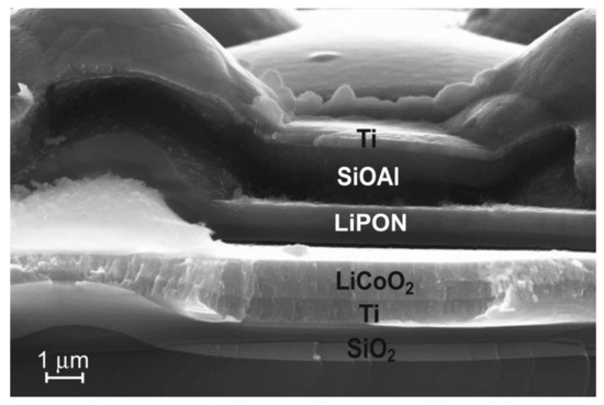
Figure 7.
SEM image of the region of the Si-O-Al layer of the 3D SSLIB-2 after lithiation–delithiation cycling.
In the area of the 3D SSLIB-2 sample, shown in Figure 7, the increase in the thickness of the Si-O-Al layer makes 150–200% compared to the initial 0.75 μm. Another proof of the lithiation–delithiation is the change in Si-O-Al internal structure in the region of the film adjacent to the solid electrolyte LiPON (Figure 8). After 3D SSLIB-2 cycling, a part of the Si-O-Al layer has divided into two structural areas: Si-O-Al-1 and Si-O-Al-2. Both layers differ in structure from the original Si-O-Al, unaffected by lithiation, but in the region of the Si-O-Al-2 layer structural changes are much greater. The Si-O-Al-2 layer has significantly more structural defects characteristic for the Si-O-Al composite, subjected to the lithiation–delithiation cycles. In addition, the layer of solid electrolyte LiPON (Figure 7 and Figure 8), judging by electronic contrast, has also subdivided into two parts. The LiPON layer located near the Si-O-Al border is lighter than the LiPON layer near the LiCoO2 border.
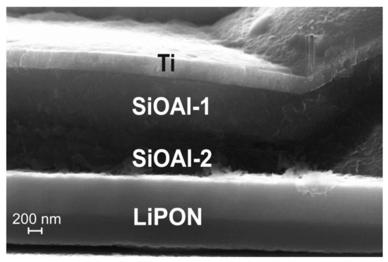
Figure 8.
SEM image of the internal structure of the Si-O-Al layer after cycling the 3D SSLIB-2.
To explain the reasons for the change in the Z-contrast of LiPON and Si-O-Al particular regions after cycling, the SSLIB-2 cleavage mapping was performed. Figure 9 shows the SEM image of the mapping area and the maps themselves. According to the Ti map, the Si-O-Al-1 region contains a large amount of titanium. The O maps clearly show that there is rather more oxygen in Si-O-Al-2 than in Si-O-Al-1. The Al map shows aluminum diffusion into the upper LiPON layer, while the O map indicates that the oxygen concentration at the boundaries of the solid electrolyte is lower than in the central part. The P map reveals that during cycling, phosphorus leaves the upper edge of the solid electrolyte and partially penetrates into the positive electrode. Finally, it follows from the Ar map that, contrary to fears, argon does not form any cavities, but remains uniformly distributed over all functional layers.
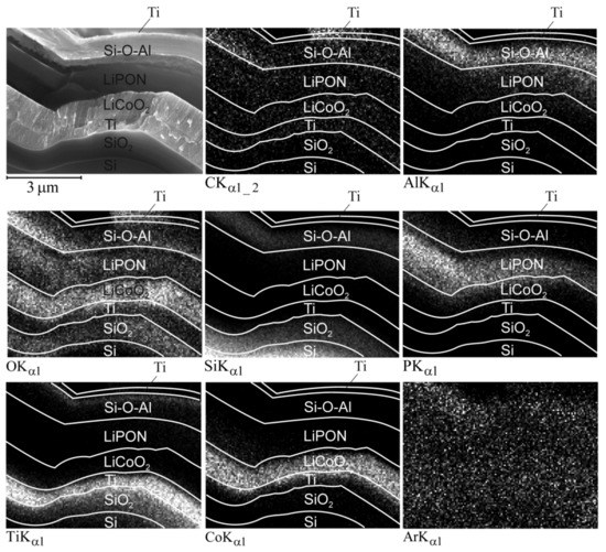
Figure 9.
SEM image and maps of 3D SSLIB-2 functional layers after cycling.
4. Conclusions
The main result of this work is a laboratory technology for manufacturing a 3D solid-state lithium-ion battery. The core of this technology is a method for a 3D structure formation on silicon substrate, based on the well-known two-stage Bosch silicon etching process. To improve the accuracy of the etching selectivity control, the Bosch process was supplemented with a third stage of a photoresist etching in an oxygen-containing plasma. The developed method for 3D relief formation enables creating structures, the aspect ratio of which is limited only by the thickness of the silicon wafer. However, in the case of high aspect ratios, the slope of the conical lateral surface increases, while the homogeneity of the deposited functional layers, on the contrary, decreases. The limiting slope angle for magnetron deposition is about 60°. On steeper slopes, functional layers also can be formed but only by plasma-chemical or atomic-layer deposition, which significantly complicates the production of layers of the required stoichiometric composition.
The developed method was used to fabricate battery substrates with an array of truncated cones with an angle of the lateral surface inclination ~45°, which makes it possible to deposit functional layers with a thickness nonuniformity of about 20%. One of the fabricated substrates was additionally polished in a solution of hydrofluoric acid, and the second was used as it was, after which the functional layers were deposited on both substrates. Further 3D SSLIBs tests have demonstrated that the battery with a smooth substrate has better performance.
Investigation of batteries’ cleavages by electron microscopy revealed that all the flaws found during the 3D SSLIB tests are related to the cones roughness caused by the discrete nature of the Bosch process. This roughness has the form of annular ledges, especially sharp in the places of maximum slope of the surface, i.e., at the bases of the cones. In these places, functional layers have a dendritic structure and do not meet the continuity demands. Thus, at the cone base a rupture can form along the entire circumference of the ledge. This is especially true for the titanium film of the down conductor, which has the smallest thickness (0.6 µm). Even if the electrical contact between the cones and valleys of the 3D structure is preserved, these contacts break at high current densities, which leads to a partial loss of battery capacity. Therefore, the process of manufacturing the substrate must be supplemented with the operations of chemical polishing of silicon dioxide layer and reoxidation. This operation effectively eliminates, first of all, sharp protrusions, which guarantees the continuity of the functional layers, and ultimately protects the battery from destruction at high current densities.
Author Contributions
A.R.—writing of original draft, methodology; A.M.—methodology, investigation; V.N.—investigation, visualization; S.K.—investigation; A.S.—conceptualization, supervision. All authors have read and agreed to the published version of the manuscript.
Funding
This research was carried out within the state assignment of Ministry of Science and Higher Education of the Russian Federation (theme No. 0856-2020-0006, АААА-А20-120030690013-7).
Institutional Review Board Statement
Not applicable.
Informed Consent Statement
Not applicable.
Data Availability Statement
Supporting reported results data can be found or get by demand at The Facilities Sharing Centre “Diagnostics of Micro- and Nanostructures” (FSC DMNS), P.G. Demidov Yaroslavl State University.
Conflicts of Interest
The authors declare that they have no conflict of interest.
References
- Sun, C.; Liu, J.; Gong, Y.; Wilkinson, D.P.; Zhang, J. Recent advances in all-solid-state rechargeable lithium batteries. Nano Energy 2017, 33, 363–386. [Google Scholar] [CrossRef] [Green Version]
- Patil, A.; Patil, V.; Shin, D.W.; Choi, J.-W.; Paik, D.-S.; Yoon, S.-J. Issue and challenges facing rechargeable thin film lithium batteries. Mat. Res. Bull. 2008, 43, 1913–1942. [Google Scholar] [CrossRef]
- Souquet, J.L.; Duclot, M. Thin film lithium batteries. Solid State Ion. 2002, 148, 375–379. [Google Scholar] [CrossRef]
- Bates, J.B.; Dudney, N.J.; Neudecker, B.; Ueda, A.; Evans, C.D. Thin-film lithium and lithium-ion batteries. Solid State Ion. 2000, 135, 33−45. [Google Scholar] [CrossRef]
- Jones, S.D.; Akridge, J.R. Thin film rechargeable Li batteries. Solid State Ion. 1994, 69, 357–368. [Google Scholar] [CrossRef]
- Dudney, N.J. Thin film micro-batteries. Electrochem. Soc. Interface 2008, 3, 44−48. [Google Scholar]
- Mendoza, N.F. Flexible Battery Market to Hit $500 Million in 2030 [Electronic Resource]/N.F. Mendoza//TechRepublic. Available online: www.techrepublic.com/article/flexible-battery-market-to-hit-500-million-in-2030 (accessed on 12 October 2020).
- Cymbet.com. 2021. Available online: https://www.cymbet.com/wp-content/uploads/2019/02/DS-72-41-v6.pdf (accessed on 9 April 2021).
- Yue, C.; Li, J.; Lin, L. Fabrication of Si-based three-dimensional microbatteries: A review. Front. Mech. Eng. 2017, 12, 459–476. [Google Scholar] [CrossRef] [Green Version]
- Moitzheim, S.; Put, B.; Vereecken, P. Advances in 3D Thin-Film Li-Ion Batteries. Adv. Mater. Interfaces 2019, 1900805, 1–17. [Google Scholar] [CrossRef]
- Talin, A.A.; Ruzmetov, D.; Kolmakov, A.; McKelvey, K.; Ware, N.; El Gabaly, F.; Dunn, B.; White, H.S. Fabrication, Testing and Simulation of All Solid State Three Dimensional Li-ion Batteries. ACS Appl. Mater. Interfaces 2016, 47, 32385–32391. [Google Scholar] [CrossRef] [PubMed] [Green Version]
- Wu, B.; Kumar, A.; Pamarthy, S. High aspect ratio silicon etch: A review. J. Appl. Phys. 2010, 108, 051101. [Google Scholar] [CrossRef]
- Rudy, A.C.; Morozov, O.V.; Kurbatov, S.V. A Modernized Bosch Etching Process for the Formationof Tapered Structures on a Silicon Surface. J. Surf. Investig. 2021, 3, 461–466. [Google Scholar] [CrossRef]
- O’Neill, F.T.; Sheridan, J.T. Photoresist reflow method of microlens production Part I: Background and experiments. Optik 2002, 113, 1–13. [Google Scholar] [CrossRef]
- Pukhov, D.E.; Lapteva, A.A. Taking into Account the Surface Roughness in the Electron-Probe Energy-Dispersive Analysis of Powder Materials. J. Surf. Investig. 2020, 14, 889–898. [Google Scholar] [CrossRef]
- Lacivita, V.; Westover, A.S.; Kercher, A.; Phillip, N.D.; Yang, G.; Veith, G.; Ceder, G.; Dudney, N.J. Resolving the Amorphous Structure of Lithium Phosphorus Oxynitride (Lipon). J. Am. Chem. Soc. 2018, 140, 11029–11038. [Google Scholar] [CrossRef] [PubMed]
- Mironenko, A.A.; Fedorov, I.S.; Rudy, A.S.; Andreev, V.N.; Gryzlov, D.Y.; Kulova, T.L.; Skundin, A.M. Charge–discharge performances of the Si–O–Al electrodes. Mon. Chem.—Chem. Mon. 2019, 150, 1753–1759. [Google Scholar] [CrossRef]
- Hausbrand, R.; Cherkashinin, G.; Ehrenberg, H.; Gröting, M.; Albe, K.; Hess, C.; Jaegermann, W. Fundamental degradation mechanisms of layered oxide Li-ion battery cathode materials: Methodology, insights and novel approaches. Mater. Sci. Eng. B 2015, 192, 3–25. [Google Scholar] [CrossRef]
- Oura, K.; Katayama, M.; Zotov, A.V.; Lifshits, V.G.; Saranin, A.A. Surface Science: An Introduction; Springer: Berlin/Heidelberg, Germany, 2010; pp. 357–387. [Google Scholar]
- Ping, W.; Yang, C.; Bao, Y.; Wang, C.; Xie, H.; Hitz, E.; Cheng, J.; Li, T.; Hu, L. A silicon anode for garnet-based all-solid-state batteries: Interfaces and nanomechanics. Energy Storage Mater. 2019, 21, 246–252. [Google Scholar] [CrossRef]
Publisher’s Note: MDPI stays neutral with regard to jurisdictional claims in published maps and institutional affiliations. |
© 2021 by the authors. Licensee MDPI, Basel, Switzerland. This article is an open access article distributed under the terms and conditions of the Creative Commons Attribution (CC BY) license (https://creativecommons.org/licenses/by/4.0/).