2.1. Experimental Samples
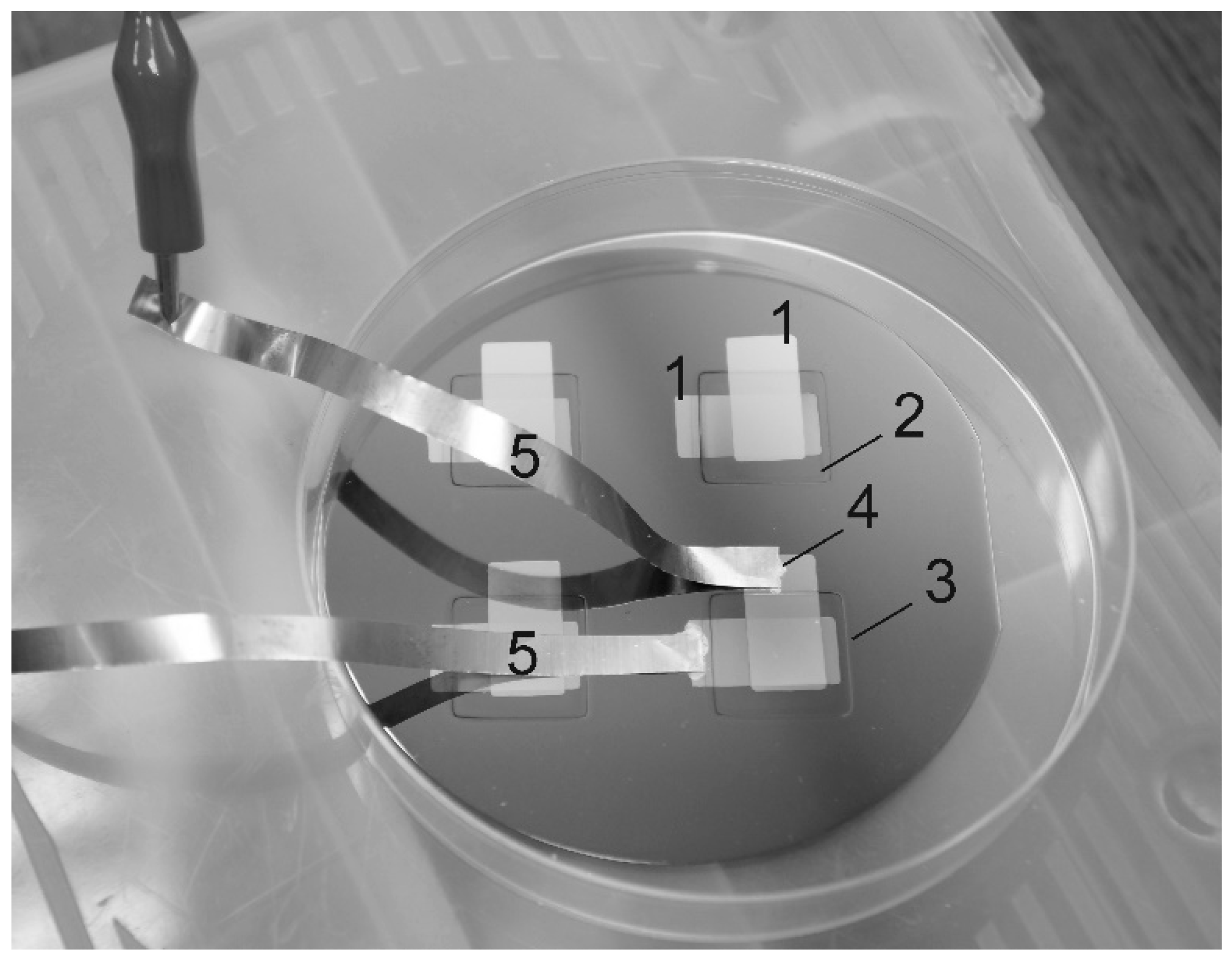
LiPON films (
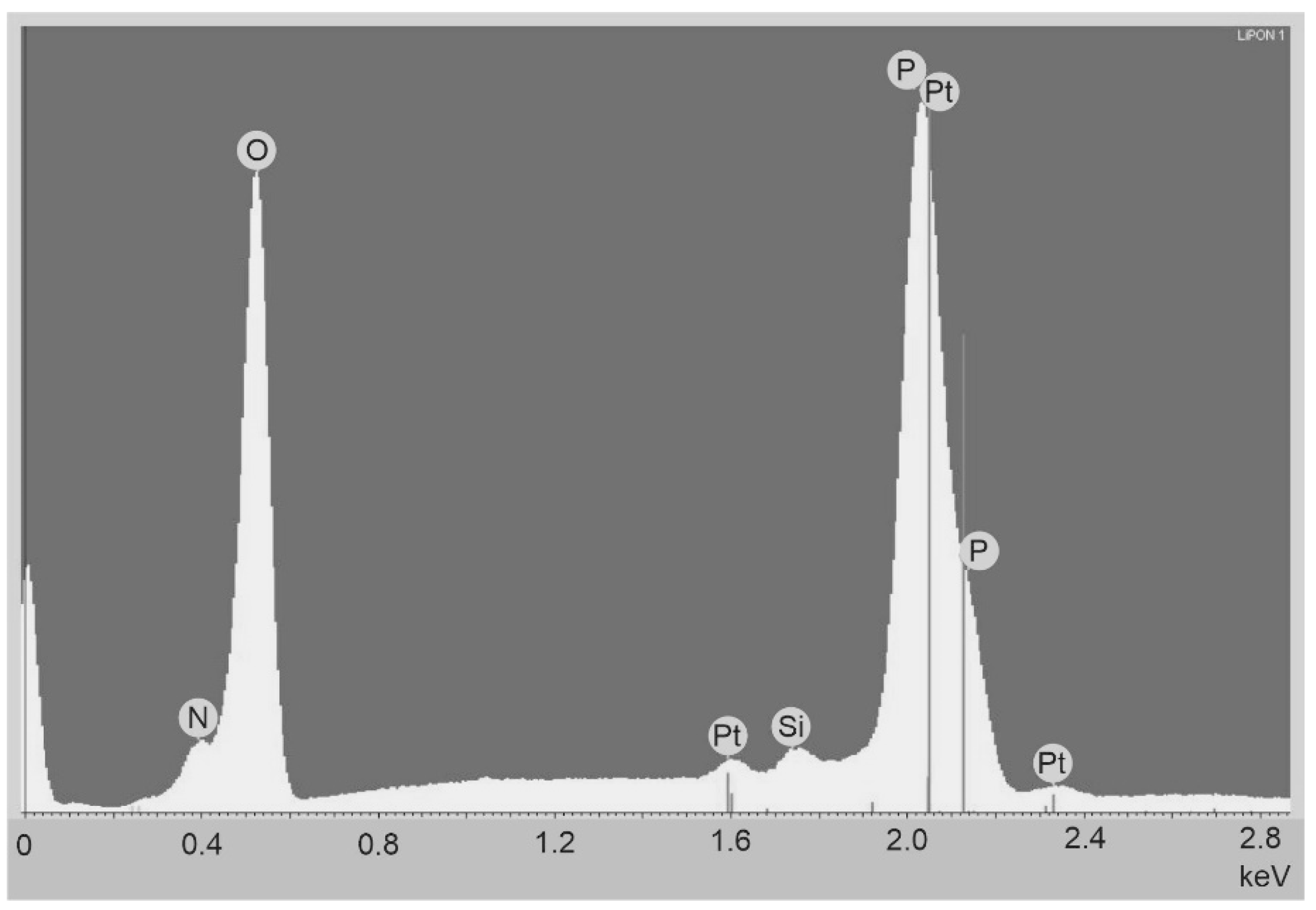
Figure 1) were deposited on the oxidized silicon wafer at a SCR-651 “Tetra” unit by magnetron sputtering of lithium orthophosphate under a nitrogen flow (18.6 standard cubic cm/min) at a residual pressure of 2 μbar. The magnetron power was 150 W, the deposition time was 3 h, and the thickness of the deposited film was 1 μm. The thickness of the platinum electrodes, deposited by magnetron sputtering, was 100 nm. Copper foil strips, attached to platinum electrodes by electroconductive glue, served as down conductors. The nitrogen concentration in the LiPON films, according to the data of energy dispersive analysis (INCAx-act EDA), was 16.8 at.% at an accelerating voltage of 5 kV and 16.5 at.% at a voltage of 7 kV (
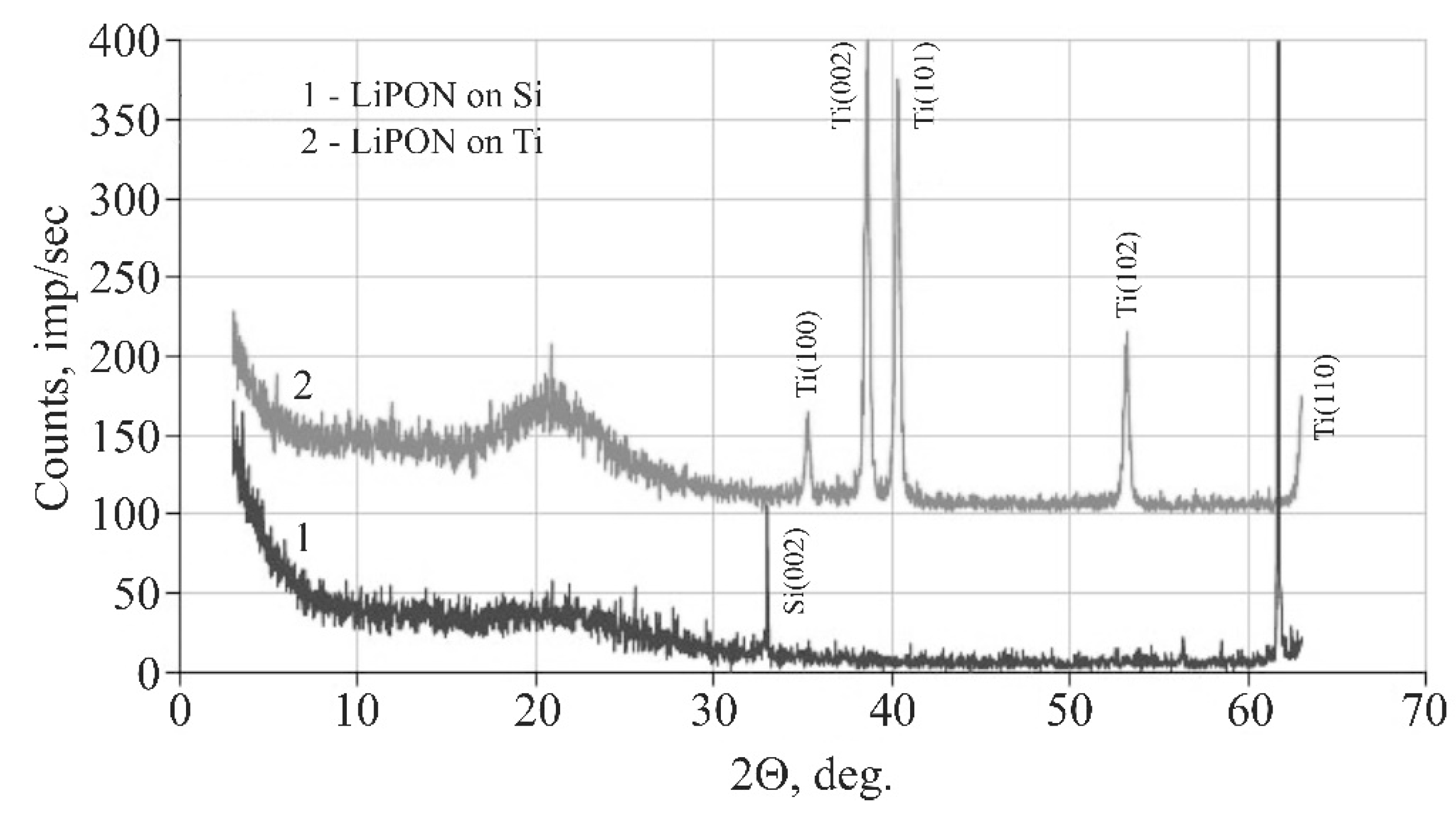
Figure 2). According to X-ray phase analysis (ARL X’tra), the LiPON films were amorphous (
Figure 3).
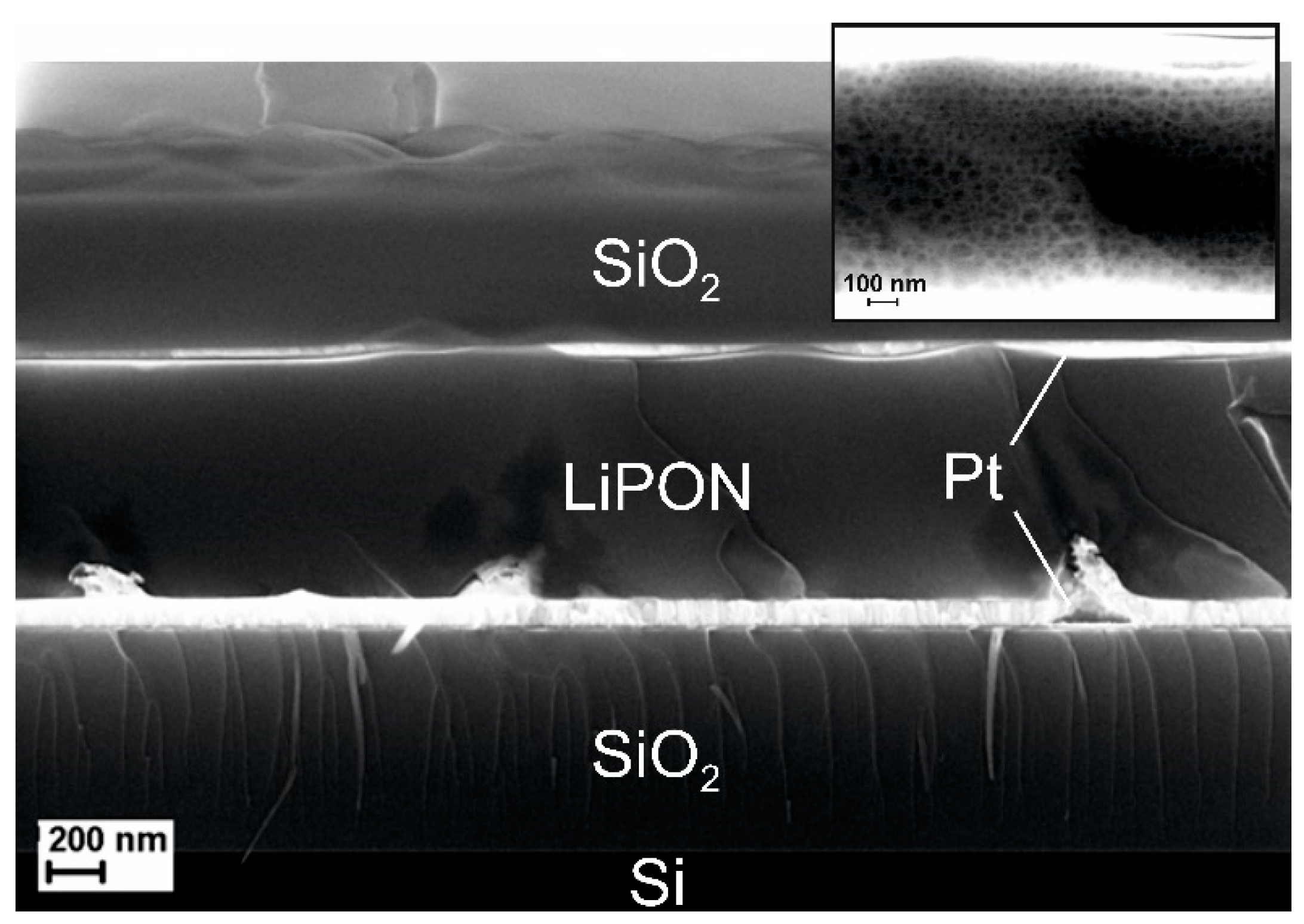
Figure 4 shows the cleavage of a Pt(100 nm)/LiPON(1 μm)/Pt(100 nm) cell. The inset shows a section of the solid LiPON electrolyte layer. The impedance spectrum obtained on a multichannel potentiostat-galvanostat P-20X8 in the frequency range of 1 Hz to 20 kHz is shown in
Figure 5.
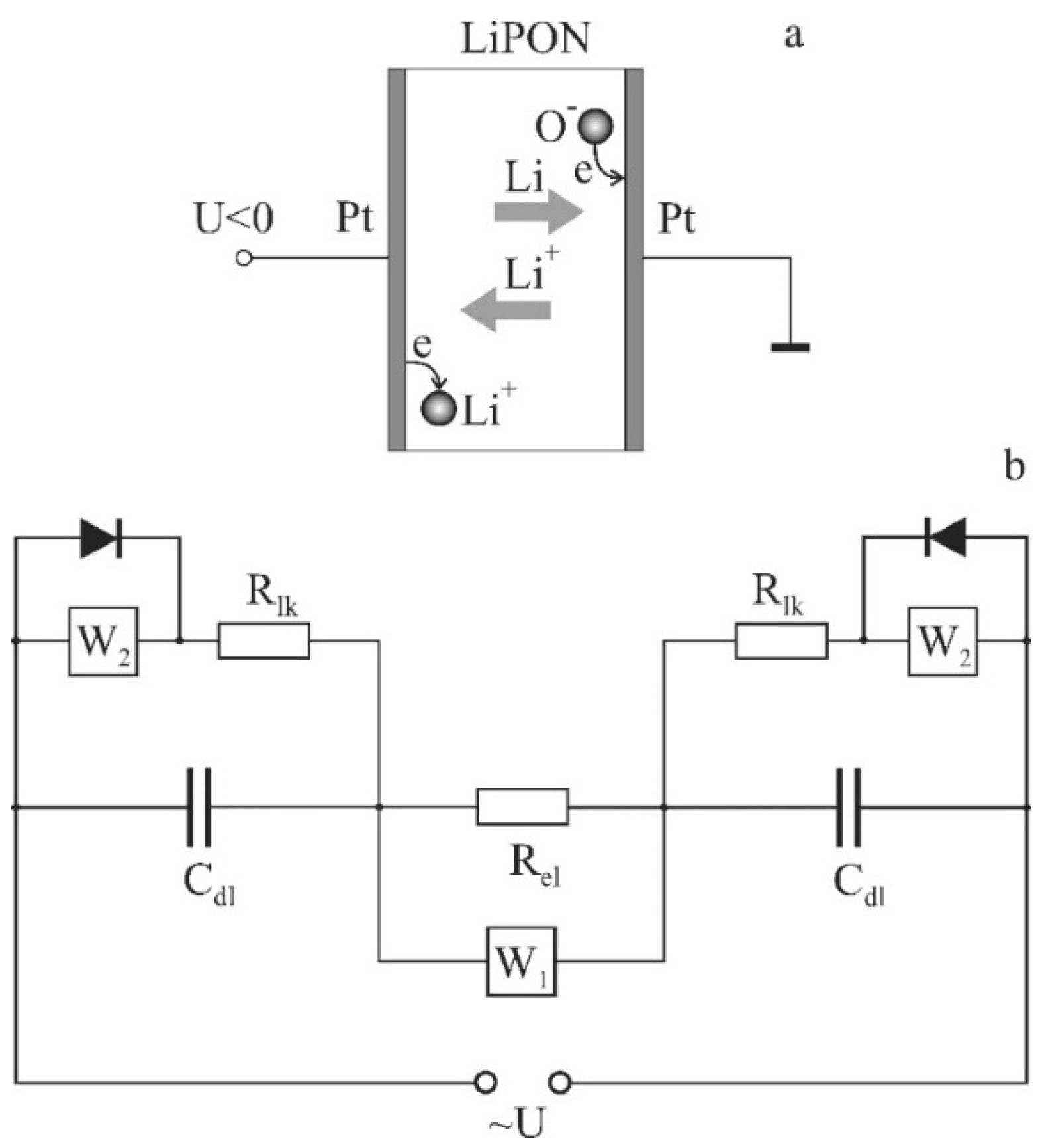
To explain the features of the obtained spectrum, a structural model, shown in
Figure 6, was proposed. When choosing a structural model, the following features of the Pt/LiPON/Pt cell were considered. First of all, it was taken into consideration that in the cell, the diffusion mechanism of charge transfer prevails. The lithium concentration gradient required to shield the external field was formed by lithium dissolved in platinum electrodes and the Faraday process. As was shown in [
2], platinum electrodes contain a large amount of dissolved lithium and, depending on the polarity, extraction or insertion of lithium occurs. In addition, according to the results of [
3], a Faraday process takes place on platinum electrodes, and the leakage current circuit is closed by the flow of the resulting lithium atoms. In other words, there are two oppositely directed diffusion flows: lithium ions and atoms.
The proposed structural model (
Figure 6) consists of two capacitors corresponding to the capacitance of an electric double layer (EDL) on platinum electrodes, connected by an active resistance and a Warburg diffusion element. These elements simulate the drift and diffusion components of the polarization current. The Faraday process is simulated by a leakage current circuit connected in parallel to each of the capacitors and consists of an active resistance and a diffusion element. Since neutral lithium atoms are formed only at the cathode, diodes are connected in parallel to the diffusion elements, which shunt the Warburg diffusion element on the electrode, which, in this half-period is, the anode. Since it is not possible to calculate the impedance of a model with such structural elements as a diode, a simplified model is considered below.
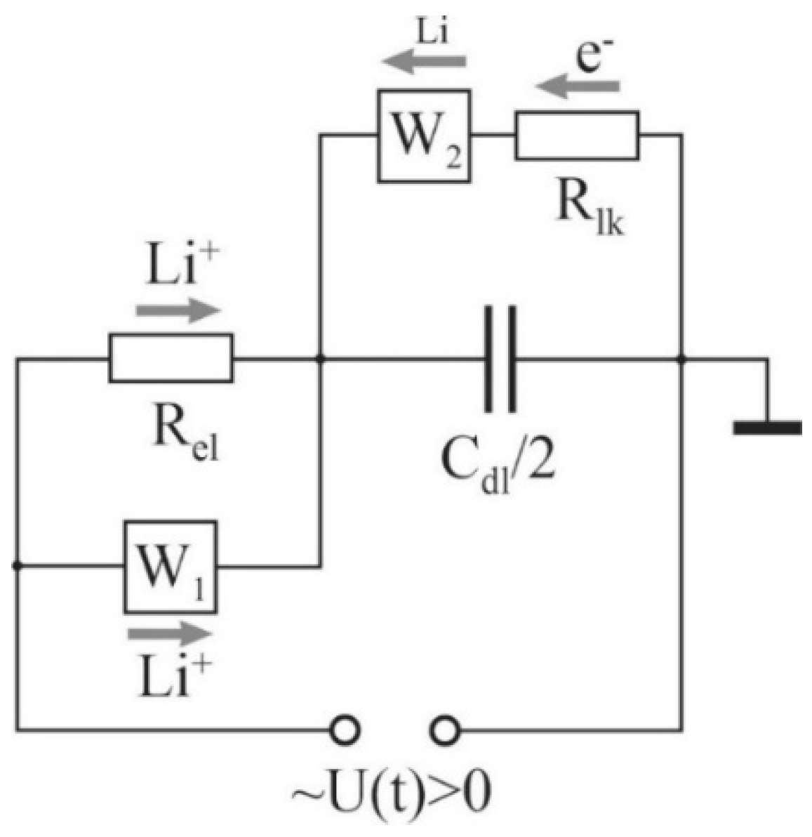
In a simplified model (
Figure 7), both EDLs were represented by one capacitor,
, and one leakage circuit. The current through the resistor,
, simulates the redox reactions at the electrodes, while its value is determined by the rate of these reactions. The leakage current circuit is closed through the Warburg element,
W2, which simulates the resistance to the diffusion flux of lithium atoms moving from the cathode to the anode, where they are oxidized again.
The impedance of the structural model shown in
Figure 7, which is calculated in the same way as the resistance of parallel and series-connected conductors, has the form
Separation of the real and imaginary parts of the impedance given by Equation (1) yields in the following expressions:
where
; Ω·s
−1/2 is Warburg coefficient;
U0, V is voltage amplitude across platinum electrodes;
D, m
2/s is diffusivity coefficient;
S, m
2 is electrode area;
q, C is ion charge;
c, m
−3 amplitude of oscillation of the nonequilibrium lithium concentration at the electrode surface.
2.2. Diffusivity and Conductivity Calculation
Equations (2) and (3) represent the parametric equation of a curve referred to as the Nyquist diagram.
Figure 2, along with the experimental Nyquist diagram, shows a diagram calculated by Equations (2) and (3) for the following values of the parameters of structural elements:
Rel = 180 Ω,
Rlk = 11,000 Ω,
Cdl = 2.1 × 10
−7 F,
AW1 = 10
4 Ω·s
−1/2, and
AW2 = 9 × 10
4 Ω·s
−1/2. The value
Rel = 180 Ω was obtained by the method described in [
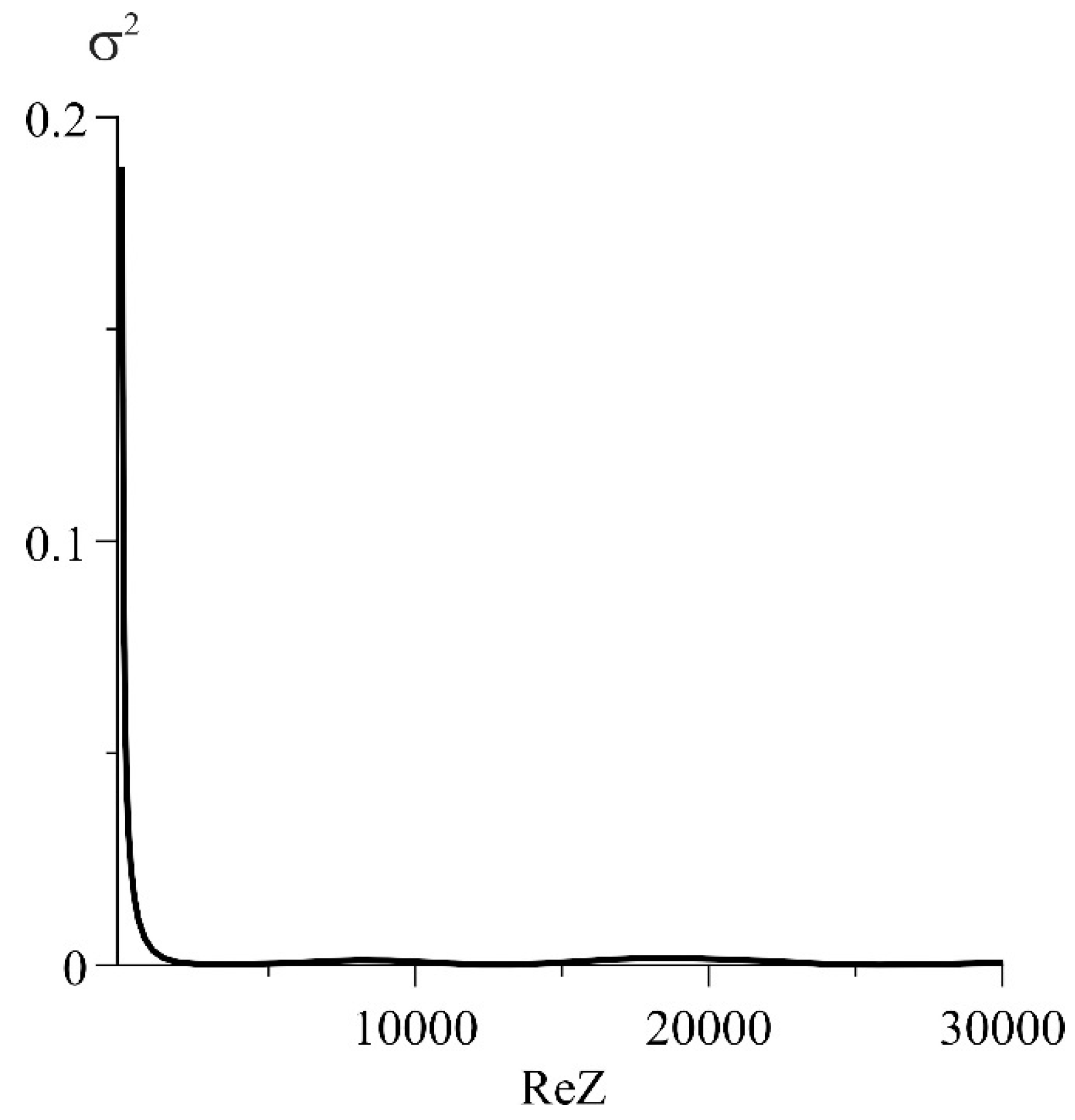
3] and was not used for fitting. The rest of the parameters were selected so that the deviation from the experimental curve, characterized by RSS (residual sum of squares), was minimal. Since the value of RSS itself does not characterize the quality of the approximation, it is expedient to use the normalized squared deviations,
, shown in
Figure 8.
Note that, at high frequencies, the discrepancy between the experimental curve and its model increases. It is possible to achieve a more accurate coincidence of the experimental and calculated diagrams by introducing a constant phase element (CPE). This is the most commonly used approach. However, the structural models obtained in this case, in spite of the perfect coincidence of appropriate diagrams with the experimental curves, hardly lend themselves to physical interpretation. Therefore, in this work, the choice is made in the favor of the physical meaning, although with some damage to the accuracy of approximation of the experimental curves. For example, in the high-frequency region, according to
Figure 7, the capacitor (
) shunts the elements
and
, and their variation does not affect the shape of the Nyquist diagram in any way. Therefore, it makes no sense to achieve full compliance of the model with the experimental curve in this area (
Figure 8).
The value of the Warburg amplitude obtained by fitting was related to the diffusion coefficient by the equation
allowing us to find the diffusion coefficient of lithium ions,
D1. For this, it was necessary to know the amplitude of oscillation (
c0) of their non-equilibrium concentration near the electrode. It is usually expressed from the Nernst equation for the electrode potential. In this case,
c0 can be expressed as the potential of a charged plane formed by an electrolyte layer with a thickness of
dLi located in the plane
x = 0 and placed in a medium of known dielectric permeability,
εr. With respect to the grounded electrode located in the plane
x =
δ, such a potential will be equal to
U0 =
Eδ, according to the Gauss theorem
. Then
, where
dLi is the diameter of the lithium ion,
q is the charge of the ion, and
δ is the thickness of the LiPON layer. Expressing the diffusion coefficient from Equation (4) and substituting
c0, we obtain the final expression for the diffusion coefficient.
In [
3], the relative dielectric permeability of LiPON was estimated as
, and the remaining parameters were
dLi = 1.56 × 10
−10 m,
δ = 10
−6 m,
AW1 = 10
4 Ω·s
−1/2, and
S = 6.4 × 10
−5 m
2. Their substitution in Equation (5) gives the value of the diffusion coefficient
D1 = 1.5 × 10
−11 cm
2/s, which is in good agreement with the data of [
4,
5].
The error in determining the diffusion coefficient can be estimated as follows. Logarithmic derivation of Equation (5) gave the dependence of the error in determining the diffusion coefficient on the Warburg amplitude of ∆D1/D1 ≈ 2∆A1/A1, since all other parameters were determined more accurately. In the course of fitting, the variation of the normalized in a vicinity of its minimum value, , was ≈0.5%, which corresponds to . Thus, the final value of the diffusion coefficient will be as follows: D1 = 1.5 (± 0.3) × 10−11 cm2/s.
The obtained value of the diffusion coefficient makes it possible to find the mobility of lithium ions,
µ = 5.8 × 10
−10 cm
2/V·s and calculate the conductivity of LiPON. The value of the concentration of lithium ions,
, required for this calculation can be found on the basis of the leakage current, which is related to the concentration by the ratio
where
is the relaxation time of the concentration of lithium ions due to reduction reactions at a cathode. In [
3], the relaxation time during the discharge of Pt/LiPON/Pt through 1 MΩ was determined as
s. In this case, Equation (6) gives the concentration value in the near-cathode layer by
cm
−3. For the obtained values of the concentration and mobility of lithium ions, the conductivity was
σ =1.9 × 10
−6 S·cm
−1. This value agrees with the data of [
6], where the conductivity of LiPON was 2.3 (± 0.7) × 10
−6 s·cm
−1, as well as with the results of [
4,
5] and a number of other works. It was noteworthy that the active resistance of LiPON, defined for a similar structure in [
3] as 180 Ω, gives the conductivity value of 0.87 × 10
−6 s·cm
−1.
The difference in the values of the amplitudes
AW1 and
AW2 was explained by the fact that
AW1 simulates the complex resistance to the diffusion flux of lithium ions, and
AW2—to the diffusion flux of lithium atoms. Indeed, when the lithium ions reached the cathode, they were reduced to atoms, creating a concentration gradient and a diffusion flux directed from the cathode to the anode. Upon reaching the anode, the lithium atoms were oxidized, closing the leakage current circuit, and then moved in the opposite direction under the action of the electric field. The concentrations of lithium ions (
) and atoms (
) at the cathode [
3] differ by three orders of magnitude. It can be expected that the amplitudes of the concentration oscillation differ by the same order, while the Warburg amplitudes differ by less than one order of magnitude. Hence, one can conclude that the diffusion coefficients of ions and atoms are also different.
