Abstract
Alongside electrical loads, it is known that temperature has a strong influence on battery behavior and lifetime. Investigations have mainly been performed at homogeneous temperatures and non-homogeneous conditions in single cells have at best been simulated. This publication presents the development of a methodology and experimental setup to investigate the influence of thermal boundary conditions during the operation of lithium-ion cells. In particular, spatially inhomogeneous and transient thermal boundary conditions and periodical electrical cycles were superimposed in different combinations. This required a thorough design of the thermal boundary conditions applied to the cells. Unlike in other contributions that rely on placing cells in a climatic chamber to control ambient air temperature, here the cell surfaces and tabs were directly connected to individual cooling and heating plates. This improves the control of the cells’ internal temperature, even with high currents accompanied by strong internal heat dissipation. The aging process over a large number of electrical cycles is presented by means of discharge capacity and impedance spectra determined in repeated intermediate characterizations. The influence of spatial temperature gradients and temporal temperature changes on the cyclic degradation is revealed. It appears that the overall temperature level is indeed a decisive parameter for capacity fade during cyclic aging, while the intensity of a temperature gradient is not as essential. Furthermore, temperature changes can have a substantial impact and potentially lead to stronger degradation than spatial inhomogeneities.
1. Introduction
It is well known that both the operation [1] and the aging [2,3] of lithium-ion cells highly depend on temperature. This dependency originates from the temperature-dependent material properties [4] and transport and reaction kinetics [5,6,7,8]. Numerous publications describe the influence of elevated temperature levels on cell aging [2,9,10,11,12]. The increasing utilization of lithium-ion cells in the automotive industry is accompanied by the application of thermal management systems to maintain performance and ensure secure operation. However, the heat transfer promoted by thermal management systems inevitably induces temperature gradients [13,14,15], which therefore directly affect the temporal and spatial temperature distribution in the cells. Distinctive temperature dependencies of cell aging at lower and higher temperatures have been identified by Gering et al. [16]. Carter et al. [17] and Atkinson et al. [18] showed the effect of small-scale temperature gradients on the performance and degradation of lithium plating in small-scale coin cells. However, it is not sufficiently known how temperature gradients and temperature changes during operation affect the aging behavior of individual cells. With a better comprehension of the influence of spatial and temporal temperature inhomogeneity on cell ageing, the design and dimensioning of thermal management systems in automotive applications can be significantly improved. Among others, installation space, weight, and energetic effort are critical parameters in vehicle development. The reduction in design complexity and lowering the energetic effort of the thermal management systems while maintaining optimal performance is a crucial aspect of the further improvement of electric vehicles.
To improve the understanding of these factors, the presented work provides experimental results revealing the respective influences of conditions such as temperature level, temperature gradients, and temperature changes on cyclic cell aging. These different thermal boundary conditions were systematically and simultaneously applied to a large number of cells and aging was quantified via capacity and impedance.
The following issues form the framework of the research and the paper:
- Long-term cycling at spatially homogeneous and steady (HS) thermal boundary conditions at defined temperature levels of the cells (reference case).
- Cell aging at spatially inhomogeneous and steady (IS) thermal boundary conditions comprising defined temperature gradients applied to the cells.
- Cell aging at homogeneous and inhomogeneous transient (HT, IT) thermal boundary conditions, periodically changing between the states defined in conditions (1) and (2).
- Discussion of the correlations between thermal boundary conditions (1)–(3) and aging during cycling.
- Discussion of different thermal management strategies based upon this.
To cover these aspects, well-defined and exact thermal boundary conditions were applied to the cell surface, both inhomogeneously and transiently, in order to be able to systematically separate the individual influences. Distinct temperature differences were selected, which allowed for the clear assignment of different aging characteristics to the corresponding thermal boundary conditions. In this context, the aim was to show, in principle, how thermal boundary conditions affect aging.
2. Experimental Setup
2.1. Description of the Cell
We investigated commercial high-power pouch cells SLPB 8043140H5 (Kokam Co., Ltd., Suwon, Republic of Korea) with a nominal capacity of 3.2 Ah, a nominal voltage of 3.7 V, and a counter-tab configuration. Its specifications are shown in Table 1. The blend cathode comprises LiCoO2 and LiNixCoyAlzO2, while the anode consists of graphite. Each chosen boundary condition was applied consistently to two cells next to each other. By accounting for all combinations of boundary conditions, the study included 24 cells.

Table 1.
Cell specifications of SLPB 8043140H5.
The cycling was performed with a XCTS (BaSyTec GmbH, Asselfingen, Germany) cell test device, while the periodical check-up experiments were carried out with a CTS Lab (BaSyTec GmbH, Asselfingen, Germany) cell test device due to the higher voltage and current accuracy. Electrochemical impedance spectroscopy (EIS) measurements were conducted using the ZENNIUM Electrochemical Workstation (ZAHNER-elektrik GmbH & Co. KG, Kronach, Germany) extended by a PMux-S cell multiplexer (ZAHNER-elektrik GmbH & Co. KG, Kronach, Germany).
All experiments were carried out in a safety chamber. The temperature directly at the cell surface was controlled using individually designed temperature control plates comprising liquid cooling and heating channels. These were supplied by thermostats, which guaranteed high temperature stability independent of the thermal load. This allowed for the temperature boundary conditions to be precisely applied on the electrode stack and the cell tabs at the same time. The different effects of the cell tab, surface, and full cell cooling on cell aging is addressed by Hunt et al. [19]. Their results show an enhanced cell aging for surface cooling compared to cell tab and the full cell cooling. In order to remove the heat generated by the current load most efficiently and to achieve the externally set boundary condition inside the cell as well as possible, both solutions for temperature control were combined here.
To ensure high reproducibility and to eliminate the influence of different mounting conditions, the cells remained in their original position during the entire test period including the intermediate characterizations, which were carried out simultaneously on multiple channels.
2.2. Boundary Conditions
To obtain reliable results, it is important to set the boundary conditions precisely and as intended. This includes the electrical, thermal, and mechanical boundary conditions, which all influence the performance of the cells and their aging behavior. The parameters selected for this study are outlined below. In particular, the thermal boundary conditions and their application onto the cells are described in detail.
2.2.1. Electrical Parameters
Since this work focuses on the thermal boundary conditions, all electrical parameters were the same for all cells. They were cycled between the cut-off voltages 4.2 V and 2.7 V for charge and discharge, respectively. The constant current (CC) was 3C (9 A in relation to the typical capacity) without a constant voltage (CV) phase. The duration of one charge and discharge cycle depends strongly on the temperature level. At lower temperatures, the voltage limits are reached earlier, resulting in a lower charge throughput, which is discussed in Section 3.4. Since the temperature changes were executed simultaneously and at predefined times, the duration of an electrical full cycle at 25 °C was specified as the reference. As a result, cells with lower charge throughput needed to pause until all cells reached the cut-off voltage. The influence on total cell aging is considered comparably small, since these cells were exposed to low temperature boundary conditions, which lead to very low calendar aging [11].
2.2.2. Thermal Parameters
The widely accepted standard temperature of 25 °C [20] was also adopted for this investigation as the reference level. With 50 °C as the upper limit and 0 °C as the lower limit value, we covered a temperature range that is typical for common uses of lithium-ion batteries. At these three temperature levels, the cells were cycled at a homogenous temperature as a reference and basis for all comparisons. The inhomogeneous temperature control was characterized by an imposed temperature gradient between these reference temperatures along the length of the cell. In these cases, the lower temperature was applied to the anode tab as its higher thermal conductivity [21] is advantageous for transient temperature control. In addition, the anode shows increased ageing at low temperatures [3,17]. Figure 1 shows the concept of the cell holders for (a) homogeneous and (b) inhomogeneous temperature control as cross-sections “H-H” and “I-I” indicated in Figure 2a,c, respectively. The temperature control plates were not only used for temperature control applied to two pouch cells next to each other, but also for mechanical clamping of the cells. Springs provided a defined and uniform surface pressure of p = 3.3 N cm−² applied to the electrode stack of each cell. The parameter was determined from the results of a preliminary investigation on the reversible pressure impact on electrochemical impedance and electrode stack swelling during charge and discharge processes. It is further supported by various references in the literature. Cannarella et al. [22] show that a surface pressure of p = 5.0 N cm−² is favorable for providing the least degradation and its scattering in the case of their investigated pouch cells. Wünsch et al. [23] reveal a significantly reduced cell aging under spring pressure bracing compared to the unbraced condition. The application of surface pressure onto electrode stacks also follows the installation condition of pouch cells within automotive cell modules or even resembles wound electrode stack configurations inside hardcase cells.
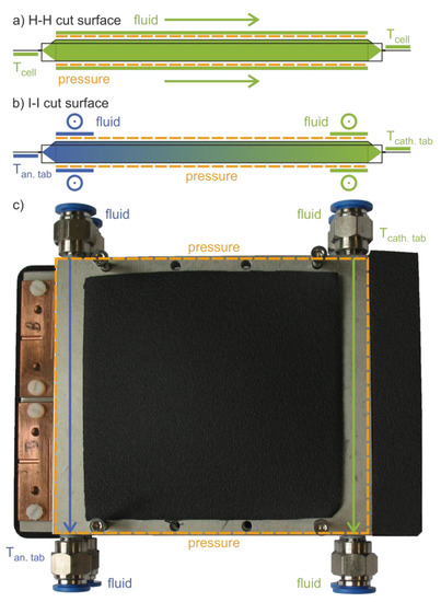
Figure 1.
Schematic cross sections H-H and I-I of two types of cell holders (compare with Figure 2), each consisting of two plates with the cell in between. (a) Homogeneous temperature control Tan.tab = Tcath.tab due to the fluid flow along the cells and at both cell tabs. (b) Inhomogeneous temperature control via fluid cross-flow at both opposing cell tabs and the corresponding edges of the electrode stack with constant Tcath.tab and Tan.tab ≠ Tcath.tab or Tan.tab as a function of time. (c) Top view of the cell holder construction for two cells next to each other as part of the inhomogeneous setups.
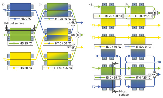
Figure 2.
Flow diagrams of the homogeneous (a) steady (HS) and (b) transient (HT) setups, as well as the inhomogeneous (c) steady (IS) and (d) transient (IT) setups.
The temperature was measured using thermocouples type K connected to a NI 9213 thermocouple module (National Instruments Corporation, Austin, TX, USA) with a measurement sensitivity of up to 0.02 °C. For a precise measurement of the absolute temperature value, the thermocouples were calibrated with a linear correction between two reference temperatures against a PT25 resistance thermometer (Anton Paar GmbH, Graz, Austria) that again was calibrated according to ITS-90 (International Temperature Scale of 1990) with measurement uncertainties of <3.6 mK in the temperature range of −40 °C to 156 °C. The thermocouples were placed in the fluid supply and return lines, as well as pressed lengthwise onto the anode tab as close as possible to the electrode stack of one cell in each assembly. The anode tab was chosen as the temperature measuring point for the cells since preliminary investigations based on the technique described by Schmidt et al. [24] revealed that for the cells, the temperature at this point was closest to the internal cell temperature. This can be attributed to the fact that the in-plane thermal conductivity of the copper and aluminum current collectors is significantly higher than the thermal conductivity perpendicular to the electrode layers [21,25]. In order to additionally shield the thermocouple against environmental influences, the temperature of the tab was controlled on the side of the current flow and the thermocouple was attached to the opposite side where the voltage measurement was located and insulated with a thin plastic sheet.
Figure 2 shows the flow diagrams of the experimental setups for (a,b) homogeneous and (c,d) inhomogeneous temperature control of 12 cells each. The solenoid valves in the transient setups (b,d) controlled the temperature changes that were synchronized with the electrical cycles. The colors blue, green, and yellow represent the temperatures 0 °C, 25 °C, and 50 °C, respectively. The different cases are specified according to the applied external thermal boundary condition, although the internal temperatures deviated from this due to heat generation during operation. Considering the average ohmic resistance of around 14 mΩ at low frequencies (compare with Figure 4b) for the 9 A current, the intensive temperature control via the cells´ surfaces and tabs kept the internal temperature increase smaller than 1 K [21,25].
Figure 2a shows the reference cases with the three base temperatures, which were homogeneously applied. For the homogeneous transient setup in Figure 2b, the color at the top shows the starting temperature. After half an electrical (dis)charge process, the solenoid valves switched and the second temperature was applied on the cells’ surface during the other half of the (dis)charge process. The same sequence was repeated for each subsequent charge and discharge.
Figure 2c,d shows the inhomogeneous setups in which a thermal gradient was applied on the cells’ surface. This gradient followed the length of the cell from one cell tab to the other. The gradient extended between the three base temperatures, with the lower temperature applied on the side of the anode tab. In the inhomogeneous steady setups shown in Figure 2c, the gradient remained constant. In the inhomogeneous transient setups of Figure 2d, the temperature on the cathode tab side of the cell remained constant, while the fluid on the side of the anode tab was switched on and off alternately in the same sequential pattern as in the HT cases. Consequently, the gradient developed and receded over time. In other words, a temperature front moved from the anode tab to the cathode tab and back again.
To ensure precise and similar thermal boundary conditions for all cells and uniform temperature changes regarding the time constants τΔT, the whole experimental setup was carefully dimensioned. This included a well-balanced pressure drop in the tubes, valves, and distributors by considering temperature dependent fluid properties, as well as the heat transfer coefficients, the heat transfer areas, and heat capacity of the cell holders. Water was used as the temperature control fluid, with ethylene glycol added for the 0 °C circuit to prevent freezing. The fluid heat transfer coefficients of the three fluid circuits, as well as the derived volume flow rates, are given in Table 2.

Table 2.
Target parameters of cooling and heating circuits.
Nusselt correlations were used to calculate the heat transfer coefficients at the inner walls of the fluid channels through the cooling plates in accordance with Gnielinski [26]. The designated fluid flow and the channel geometry within the cooling plates resulted in a flow in the transition regime between laminar and turbulent flow.
The pressure drop for fluid flow in channels, hoses, and check valves was calculated based on common correlations [27] and geometry information from data sheets. The contributions to pressure loss due to elbows, solenoid valves, and cross-sectional changes were also considered using corresponding pressure loss coefficients.
This approach enabled a precise application of the targeted thermal boundary conditions with a very high temperature accuracy, which is not even feasible for the homogeneous steady conditions with the use of a climatic chamber.
2.3. Verification of the Experimental Setup
Prior to the actual aging experiments, the test stand was characterized and tested for its suitability for the planned test series. These preliminary tests were carried out for both thermal and electrical performance.
Figure 3a shows the results for the impedance measurements on a 1 mΩ reference resistor, both for measurements directly at the workstation and for measurements with the multiplexer and the entire final wiring. The excitation was applied with a galvanostatic signal of 1 A in a frequency range of 1 Hz to 500 Hz. The blue markers are the measurement points recorded with the electrochemical workstation on the different channels. These values scatter around the reference value. The curves show the impedance that was mainly generated in the inductive range due to the wiring. This could not be avoided, but the curve progression is independent of the channel used and is within a range that is one order of magnitude smaller than the later measurement results. Therefore, the impact on the results is considered negligible.
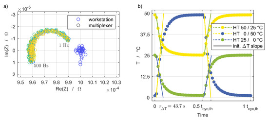
Figure 3.
(a) Test measurements of the electrochemical workstation and multiplexer with a 1 mΩ reference resistor using the wiring employed for the cell characterization. Excitation of 1 A amplitude and frequency sweep between 1 Hz and 500 Hz. (b) Preliminary thermal cycling test snippet of simultaneous temperature changes of the homogeneous transient (HT) setups.
Figure 3b provides an example of the temperature changes of the homogeneous transient setups measured at the central position between each pair of cell holder plates. The duration of a full thermal cycle tcyc,th was 600 s during the preliminary thermal cycling test. The setups exhibited uniform thermal time constants of τΔT = 43.7 s for both half-cycles of temperature rising and falling, independent of the temperature step and level. In the aging experiments, the duration of a full thermal cycle tcyc,th was 980 s at the beginning and was continuously synchronized with the duration of half an electrical cycle tcyc,el, which was split into discharge and charge periods.
Table 3 and Table 4 provide an overview of the results obtained in the preliminary thermal cycling tests for both types of transient setups during 500 thermal cycles. The achieved averaged temperatures Ø T show a slight deviation from the designated reference temperatures due to the absence of thermal insulation, which was added later in the aging experiments. The reproducibility Ø ΔT during the steady-state period of the temperature changes after 5 τΔT is smaller than the expected measurement uncertainty of 50 mK of the thermocouples based on the calibration in advance. The varying upper temperature level at the inhomogeneous transient setups shown in Table 4 is the expected result of the one-sided fluid heat transfer during heat-up periods (compare with the flow diagram in Figure 2d). The design of the cell holders regarding their heat capacity and the corresponding heat transfer was based on the fluid cross-flow at both opposing cell tabs. In this particular case, an additional cross-flow of heating fluid would be required during the one-sided heat up periods to achieve the reference temperatures. This was omitted to reproduce a one-sided, intermittent cooling strategy.

Table 3.
Preliminary thermal cycling results of homogeneous transient setups (HT) measured at the central position between each pair of cell holder plates during steady-state sections.

Table 4.
Preliminary thermal cycling test of inhomogeneous transient setups (IT) measured at the central position between each pair of cell holder plates during steady-state sections.
2.4. Testing Procedure
Repeated intermediate examinations were required to reveal the progress of degradation with the increasing number of cycles. However, their impact on cell degradation must be kept as small as possible. They were carried out at 25 °C for all tested cells and included the measurement of the actual capacity, the quasi-open-circuit voltage (OCV), and both current pulse and EIS measurements at different states of charge (SoC).
The actual capacity for setting the SoC was determined using a C/2 discharge after the cell was charged with the same current in CC-CV mode until a cut-off current of C/20 was reached. The quasi-OCV shown in Figure 4a was measured with a low C-rate of C/20 and is used for the analysis of the discharge capacity. The current pulse resistance was determined via applying a discharge pulse of 1C over 18 s at 20%, 35%, 50%, 65%, and 80% SoC and measuring the voltage response. This was chosen in accordance with the first current pulse of the pulse power characterization profile for high-power cells [20], but with a reduced excitation current of 1C to limit the change of SoC to 0.5% per pulse. The impedance spectra were measured via EIS at the same SoC using galvanostatic excitation with an amplitude current of 1 A within the frequency range from 25 mHz to 100 kHz, as shown in Figure 4b. The further discussion of degradation effects is based on the comparison of measurements at 50% SoC to provide a preferably stable cell state during the aging process. At this point, both the cell voltage and the impedance exhibit a weak dependence on SoC, and therefore lowered the risk of misinterpreting shifts in electrode alignment as aging effects [28].
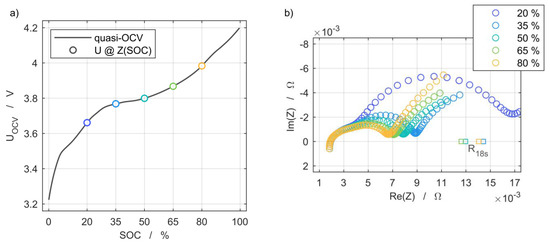
Figure 4.
(a) Open-circuit voltage characteristic at 25 °C and indicated state of charge (SoC) levels of electrochemical impedance spectroscopy (EIS) and current pulse resistance measurement grid points, and (b) their dependency on the SoC at 25 °C.
3. Results and Discussion
3.1. Initial State
The 24 cells were exposed to 50 full cycles at 1C and a temperature of 25 °C prior to the begin of life (BoL) characterization of the study with measurements of the electrochemical impedance being performed at -50, -20, -10, and 0 cycles. The exemplary results of one cell are shown in Figure 3a and indicate the definition of the BoL state based on a first-time increasing polarization resistance while the discharge capacity was already stable. The same applied to the other 23 cells.
The initial state and the scattering of the cells at the attained BoL state were further characterized by means of discharge capacity and electrochemical impedance spectra measurements. The average capacity (µ) of the cells at the BoL state was 3.013 Ah. The scattering is shown in Figure 5b. One outlier with an initial capacity of 2.752 Ah is omitted for the calculation of the normal distribution. This cell was part of the inhomogeneous steady setup at 0/25 °C and its peculiar decrease of the SoH can be seen in Figure 7c. The same applies to the impedance scattering shown in Figure 5b. Although another outlier is considered for the calculation and leads to the wide normal distribution, it is not shown in the figure due to its position at µ + 4 σ.
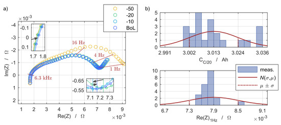
Figure 5.
(a) Transition of the polarization effects and ohmic resistance during preliminary characterizations based on electrochemical impedance spectra prior to the definition of the begin of life (BoL) state. (b) Begin of life state deviation and normal distribution N(σ,µ) of the C/20 cell discharge capacity and real part of the electrochemical impedance evaluated at 1 Hz to briefly compare the polarization effects.
3.2. Impact of Thermal Boundary Conditions
The temperature during cycling influences almost all processes taking place within the cell. The effects on the respective cell voltage curve of the homogeneous steady (HS) setups are shown in Figure 6a. The dashed lines illustrate the discharge process of the first electrical cycle at 3C. This clearly shows that the discharge capacity was reduced with decreasing temperature, and at a temperature of 0 °C, only about one third of the discharge capacity was reached compared to at 50 °C. The solid lines show the cell voltage for the 3C discharge at the end of life (EoL) state. For all temperatures, the EoL curves are below the BoL curves, indicating an increased impedance, which is discussed in Section 3.4. In addition, the discharge capacity at C/20 was reduced compared to the BoL state.
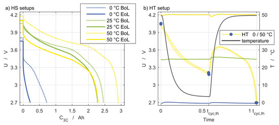
Figure 6.
(a) Voltage curves for the three reference temperatures at the BoL and EoL states. (b) Temperature for the homogeneous setup and the voltage curve for HT 0/50 °C as an example.
Figure 6b provides an example for the cell voltage response of a discharge process of the HT 0/50 °C setup and illustrates the great impact of the temperature on cell voltage behavior. The reference temperatures of the stationary setups were almost constant at 0 °C, 25 °C, and 50 °C. The solid black line shows the inlet temperature of the HT 0/50 °C setup with the inlet temperature change of 50 K after half of the discharge process. At this point, the temperature change during discharge is recognizable by the immediate voltage increase of both cells within the cell holder, which is shown as the dashed yellow line.
3.3. Capacity Measurement
Figure 7 depicts the remaining discharge capacity in percent related to the capacity at the BoL state plotted over the number of equivalent full cycles (EFCs). The designations (a–d) correspond to those of the flow diagrams in Figure 2. The EFC of each cell are based on the charge throughput at its BoL state for the reference case of homogeneous temperature control at 25 °C. Each marker represents one capacity measurement at C/20 obtained during the intermediate characterizations. The coloring of the markers and curves represents the temperature level, while the style indicates the mode of temperature control. Squares and circles stand for homogeneous temperature control, while diamonds and triangles are used for inhomogeneous temperature control. The solid lines refer to steady temperature control and the dashed lines refer to transient temperature control.
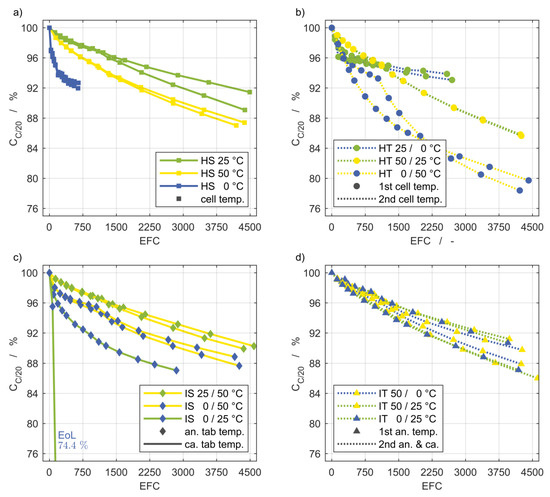
Figure 7.
Discharge capacity fade of the setups shown as flow diagrams in Figure 2. The markers indicate intermediate cell characterizations and anode tab temperature of inhomogeneous setups. The homogeneous stationary and transient setups are shown in (a) and (b). The inhomogeneous stationary und transient setups are shown in (c) and (d). The EoL capacity of one cell of the inhomogeneous, steady (IS) 0/25 °C setup is outside the scale and therefore noted separately. EFC: Equivalent full cycle.
Figure 7a shows the curves for the homogeneous steady temperature control at 25 °C (green), 50 °C (yellow), and 0 °C (blue). As expected, the capacity fade of cells cycled at a temperature of 25 °C was the lowest. The capacity declined faster for both increasing and decreasing temperature, which is more pronounced at 0 °C than at 50 °C. The low charge throughput at 0 °C was noticeable and can be explained by high overvoltages at low temperatures.
The influence of temperature changes over time between two temperatures can be seen in Figure 7b. Especially for the changes over the wide temperature range of 50 K, a significantly higher loss of capacity was recorded. Comparing the HT 0/50 °C and HT 0/50 °C setups, it should be noted that the sequence of heating and cooling was reversed. For the former, the influence of the colder temperature at the end of the charging period can be seen in a reduced charge throughput.
Figure 7c shows the capacity fade for the applied thermal gradients. The capacity of one cell for the IS 0/25 °C setup dropped off dramatically. We assume that a manufacturing defect occurred in this cell since the second one with the same boundary condition showed a reasonable progression.
A comparison of the capacity loss of the steady tests (Figure 7a,c) shows that lowering the temperature at the anode tab from 50 °C to 25 °C results in approximately the same capacity fade as the cells with a homogeneous temperature control of 25 °C. If the temperature at the anode tab is further reduced to 0 °C, there is hardly any change compared to the HS 50 °C setup. In contrast, a temperature of 0 °C at the anode tab combined with a temperature of 25 °C at the cathode tab has a serious effect on the capacity, compared to cycling at a homogeneous temperature of 25 °C.
Comparing the results of Figure 7b,c reveals that a permanent temperature gradient between 0 °C and 50 °C has less of an effect on the capacity fade than temperature changes between the same temperatures.
The evolution of the capacities for the inhomogeneous transient setup in Figure 2d do not vary sufficiently with the different boundary conditions to allow for a meaningful interpretation.
3.4. Impedance Measurement
The increase of the impedance spectra obtained at the three homogeneous steady setups (HS) that are designated as reference and at one selected inhomogeneous steady setup (IS) are shown in Figure 8, as well as the corresponding current pulse resistance measurements. For the sake of clarity, not all intermediate characterizations are included. The IS 0/25 °C setup is selected due to the most significant degradation occurring at this inhomogeneous thermal boundary condition. Each of these spectra and current pulse resistance measurements was recorded at a state of charge (SoC) of 50% and a temperature of 25 °C.
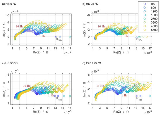
Figure 8.
The electrochemical impedance degradation and current pulse resistance increase at the three base temperatures of the homogeneous steady setup is shown in (a–c). The influence of the steady thermal gradient in the case of IS 0/25 °C is shown in (d).
For all four selected boundary conditions, the impedance rises noticeably with the increasing number of cycles, but to varied degrees and in different frequency ranges. At high frequencies, there is hardly any change. Only for the HS 50 °C setup does the intercept with the real-part axis shift to the right, which can be attributed to an increasing ohmic resistance. The growth of the second semicircle is pronounced under all boundary conditions. The overall increase in impedance is lowest at the HS 25 °C setup, which is in line with the expectation that this temperature level and distribution is the least-damaging scenario. The same applies qualitatively to the current pulse resistances, which are located on the real-part axis due to the time domain measurement principle. The results of these measurements are located at comparably higher real parts since the 18 s current pulse also excites slower processes.
3.5. Thermal Management Strategies
In order to ensure quantitative comparability despite different charge throughput, Figure 9 shows the capacity fade of the last characterization with reference to the EFC. An influence of the characteristic curve shape as a result of individual capacity fade is neglected in the context of this consideration.
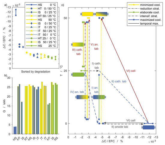
Figure 9.
Discharge capacity fade at the last characterization with reference to equivalent full cycles. (a) Setups sorted based on their impact on the capacity fade, ranging from the maximum for HS 0 °C to HS 25 °C, and (b) the corresponding charge throughput. (c) Effects of different strategies for the intensification (steps I and II) or reduction (steps III, IV, and V) of the cooling effort and the impact on capacity fade starting from HS 25 °C control.
In Figure 9a, the remaining capacity of the cells after the last cycle is given as discussed in Section 3.3 and is sorted according to their value. Their entries in the legend correspond to the ranking, beginning with the highest capacity loss down to the lowest. The same ordering is given in Figure 9b. This figure shows the different charge throughput of all setups. Higher values indicate an increased electrochemical performance due to reduced loss processes during cycling, not necessarily related to aging. The HT 25/0 °C setup, for instance, has a similar capacity loss per EFC compared to the HS 25 °C or IT 50/0 °C setups, but with a significantly lower charge throughput. The available power at given voltage limits and current is therefore lower. Consequently, this boundary condition is not preferred, despite low aging. Also noteworthy is the low charge throughput of the HS 0 °C setup, which was caused by higher overvoltages at low the temperature.
Figure 9c illustrates the influence of selected thermal boundary conditions on the capacity loss. Starting from the reference case of a homogeneous steady temperature at 25 °C (HS 25 °C), in the following, the temperatures applied at the anode and cathode tabs are varied step by step; in the first steps, cooling is intensified, which is represented by the dashed lines.
Step I: A temperature gradient of 25 K is achieved by lowering the anode tab temperature to 0 °C while the temperature of the cathode tab remains at 25 °C (IS 0/25 °C).
Step II: After the anode tab temperature is reduced, the cathode tab temperature is lowered to 0 °C as well (HS 0 °C). This maximizes cooling and causes by far the highest capacity loss within this study. The capacity fade per EFC for HS 0 °C is almost ten times higher than for HS 50 °C (compare step V).
Instead of an intensified cooling strategy, the dash-dotted lines represent reduced cooling.
Step III: Starting again at the initial 25 °C, the cathode tab temperature is raised to 50 °C (IS 50/25 °C). This results in the same temperature gradient of 25 K as in IS 0/25 °C (compare step I). Despite the same gradient, both setups showed significantly different capacity fades.
Step IV: Subsequent to step III, the anode tab temperature is lowered to 0 °C (IS 0/50 °C) to achieve a temperature gradient of 50 K.
This setup exhibited a remarkably lower capacity fade than the IS 0/25 °C setup with a gradient of 25 K. It can therefore be stated that higher gradients do not necessarily lead to accelerated aging, but rather the overall temperature level of the cell is of greater relevance.
This shows that a reduction in the temperature level leads to a more severe aging than a corresponding increase of the same magnitude. This is evident in Figure 9c, not only for the inhomogeneous boundary conditions, but also for the homogeneous comparison cases, starting again from the generally assumed basis of 25 °C and changing the applied temperature homogenously.
Step V: After the cathode tab temperature is increased (compare with step III), the anode tab temperature is raised to 50 °C as well (HS 50 °C).
In these cases, the capacity fade per EFC for HS 0 °C is almost ten times higher than for HS 50 °C.
Step VI: Steps II and V are combined such that the cell temperature changes between 0 °C and 50 °C (HT 0/50 °C). This setup is also included in Figure 9c as an example for the homogeneous transient boundary conditions. This demonstrates that temperature changes between two temperatures can have a stronger impact than temperature gradients between the same two temperatures that are permanently in place.
The results of the three inhomogeneous transient (IT) setups in Figure 9a reveal a moderate and uniform capacity fade that is slightly increased compared to the HS 25 °C setup. The scattering does not allow for distinguishing between the setups regarding their capacity fade. Requirements on spatial and temporal temperature homogeneity within the cells are totally disregarded and apparently superfluous in the case of the IT 50/0 °C setup. In contrast, the energetic effort increases considerably if a coolant has to be provided at a temperature level of 0 °C.
Awareness of these influences in the application is beneficial for the design and dimensioning of temperature control systems. It is possible to estimate, at least qualitatively, which effort is reasonably required regarding (i) the geometric design complexity of a cooling system (e.g., number, length, and pathway of coolant flow), and (ii) the effort required for achieving a certain cooling medium temperature level. Such qualitative evaluations of the boundary conditions covered in this work are presented in Table 5. Therein, the order in which the setups are listed corresponds to the sorting in Figure 9a in accordance with the cells´ capacity loss (iii).

Table 5.
Evaluation of the setups by means of their thermal boundary condition and its impact on degradation, sorted according to the capacity loss shown in Figure 9a.
The consideration of the constructive effort is based on the idea that the temperature of the entire cell surface is controlled to achieve a homogeneous cell temperature. If temperature gradients are permitted in an application, it can be sufficient to control the temperature of the cells only from one side, which results in a reduced design complexity (i). The other side without temperature control in such an application is here represented by the higher temperature, which is also controlled to enable a systematic comparison between the setups. In the case of the HT 25/0 °C setup, the increase of the design complexity (i) for achieving a homogeneous temperature boundary condition compared to the IT 0/25 °C setup led to an only slightly decreased capacity fade. The opposite applies to the comparison between the HT 50/25 °C and IT 50/25 °C setups.
In addition to the one-sided cooling, a low volume flow of the temperature control fluid, which is then warmed up by the heat dissipation of the cell, can also lead to temperature gradients in the direction of the fluid flow. This is independent of the design complexity and is taken into account in the effort for coolant system (ii), as the temperature regulation of a high volume flow is assumed to be more extensive.
The comparison of all three setups comprising the 25 °C and 50 °C temperature level clearly shows that the cell aging decreased significantly with the reduction of the cell volume fraction that underwent 25 K temperature changes, ranging from the HT over IT to the IS setup.
In the overall view of all setups for the investigated pouch cell, an inhomogeneous steady temperature boundary condition between 25 °C and 50 °C seems most advantageous regarding the reduced design complexity and energetic effort for the coolant system, and shows the lowest discharge capacity degradation and the highest charge throughput at the same time.
4. Conclusions
We have undertaken an experimental investigation on the effect of defined complex thermal boundary conditions on cyclic cell aging. The results are presented in terms of the capacity fade and impedance rise during aging. It can be stated that higher gradients do not necessarily lead to accelerated aging, but instead, the overall temperature level of the cell is of greater relevance. Temperature changes between two temperatures can have a stronger impact than temperature gradients between the same two temperatures that are permanently in place. Awareness of these influences in the application is beneficial for the design and dimensioning of temperature control systems. Since this experimental study is the first of its kind, it is not yet certain to what extent these statements can be transferred to other cell chemistries. However, it offers indications as to how the lifetime in the application can be extended using suitable temperature control.
For the investigated pouch cell, an inhomogeneous steady temperature boundary condition between 25 °C and 50 °C seems most advantageous by causing reduced constructive and energetic effort, the least discharge capacity degradation, and the highest charge throughput at the same time.
The impacts of all discussed thermal boundary conditions on quantities other than discharge capacity, as well as further evaluations, are content of the second part of this publication.
Author Contributions
Conceptualization, D.W., A.W., and T.W.; methodology, D.W. and A.W.; software, D.W.; validation, D.W. and S.P.; formal analysis, D.W.; investigation, D.W.; writing—original draft preparation, D.W. and S.P.; writing—review and editing, D.W., S.P., and T.W.; visualization, D.W. and S.P.; supervision, A.W. and T.W.; project administration, A.W. and T.W.; funding acquisition, A.W. and T.W. All authors have read and agreed to the published version of the manuscript.
Funding
This research was funded by MAHLE International GmbH and the federal state of Baden-Württemberg as part of the graduate school “Projekthaus e-drive.” The APC was funded by the Institute of Thermal Process Engineering (TVT), Karlsruhe Institute of Technology (KIT).
Acknowledgments
The authors would like to thank Michael Weiss (Institute for Applied Materials - Materials for Electrical and Electronic Engineering (IAM-WET), Karlsruhe Institute of Technology (KIT)) for the scientific discussions.
Conflicts of Interest
The authors declare no conflict of interest.
References
- Bandhauer, T.M.; Garimella, S.; Fuller, T.F. A Critical Review of Thermal Issues in Lithium-Ion Batteries. J. Electrochem. Soc. 2011, 158, R1. [Google Scholar] [CrossRef]
- Bloom, I.D.; Cole, B.W.; Sohn, J.J.; Jones, S.A.; Polzin, E.G.; Battaglia, V.S.; Henriksen, G.L.; Motloch, C.G.; Richardson, R.A.; Unkelhaeuser, T.; et al. An accelerated calendar and cycle life study of Li-ion cells. J. Power Sources 2001, 101, 238–247. [Google Scholar] [CrossRef]
- Vetter, J.; Novák, P.; Wagner, M.R.; Veit, C.; Möller, K.-C.; Besenhard, J.O.; Winter, M.; Wohlfahrt-Mehrens, M.; Vogler, C.; Hammouche, A. Ageing mechanisms in lithium-ion batteries. J. Power Sources 2005, 147, 269–281. [Google Scholar] [CrossRef]
- Maleki, H. Thermal Properties of Lithium-Ion Battery and Components. J. Electrochem. Soc. 1999, 146, 947. [Google Scholar] [CrossRef]
- Arrhenius, S. Über die Reaktionsgeschwindigkeit bei der Inversion von Rohrzucker durch Säuren. Zeitschrift Phys. Chem. 1889, 4U. [Google Scholar]
- Newman, J.; Tiedemann, W. Porous-electrode theory with battery applications. AIChE J. 1975, 21, 25–41. [Google Scholar] [CrossRef]
- Bernardi, D. A General Energy Balance for Battery Systems. J. Electrochem. Soc. 1985, 132, 5. [Google Scholar] [CrossRef]
- Mistry, A.; Fear, C.; Carter, R.; Love, C.T.; Mukherjee, P.P. Electrolyte Confinement Alters Lithium Electrodeposition. ACS Energy Lett. 2019, 4, 156–162. [Google Scholar] [CrossRef]
- Ramadass, P.; Haran, B.; White, R.; Popov, B.N. Capacity fade of Sony 18650 cells cycled at elevated temperatures Part I. Cycling performance. J. Power Sources 2002, 112, 606–613. [Google Scholar] [CrossRef]
- Ramadass, P.; Haran, B.; White, R.; Popov, B.N. Capacity fade of Sony 18650 cells cycled at elevated temperatures Part II. Capacity fade analysis. J. Power Sources 2002, 112, 614–620. [Google Scholar] [CrossRef]
- Schmalstieg, J.; Käbitz, S.; Ecker, M.; Sauer, D.U. A holistic aging model for Li(NiMnCo)O2 based 18650 lithium-ion batteries. J. Power Sources 2014, 257, 325–334. [Google Scholar] [CrossRef]
- Schuster, S.F.; Bach, T.; Fleder, E.; Müller, J.; Brand, M.; Sextl, G.; Jossen, A. Nonlinear aging characteristics of lithium-ion cells under different operational conditions. J. Energy Storage 2015, 1, 44–53. [Google Scholar] [CrossRef]
- Troxler, Y.; Wu, B.; Marinescu, M.; Yufit, V.; Patel, Y.; Marquis, A.J.; Brandon, N.P.; Offer, G.J. The effect of thermal gradients on the performance of lithium-ion batteries. J. Power Sources 2014, 247, 1018–1025. [Google Scholar] [CrossRef]
- Klein, M.; Tong, S.; Park, J.W. In-plane nonuniform temperature effects on the performance of a large-format lithium-ion pouch cell. Appl. Energy 2016, 165, 639–647. [Google Scholar] [CrossRef]
- Chen, D.; Jiang, J.; Kim, G.-H.; Yang, C.; Pesaran, A. Comparison of different cooling methods for lithium ion battery cells. Appl. Therm. Eng. 2016, 94, 846–854. [Google Scholar] [CrossRef]
- Gering, K.L.; Sazhin, S.V.; Jamison, D.K.; Michelbacher, C.J.; Liaw, B.Y.; Dubarry, M.; Cugnet, M. Investigation of path dependence in commercial lithium-ion cells chosen for plug-in hybrid vehicle duty cycle protocols. J. Power Sources 2011, 196, 3395–3403. [Google Scholar] [CrossRef]
- Carter, R.; Love, C.T. Modulation of Lithium Plating in Li-Ion Batteries with External Thermal Gradient. ACS Appl. Mater. Interfaces 2018, 10, 26328–26334. [Google Scholar] [CrossRef]
- Atkinson, R.W.; Carter, R.; Love, C.T. Operational strategy to stabilize lithium metal anodes by applied thermal gradient. Energy Storage Mater. 2019, 22, 18–28. [Google Scholar] [CrossRef]
- Hunt, I.A.; Zhao, Y.; Patel, Y.; Offer, J. Surface Cooling Causes Accelerated Degradation Compared to Tab Cooling for Lithium-Ion Pouch Cells. J. Electrochem. Soc. 2016, 163, A1846–A1852. [Google Scholar] [CrossRef]
- ISO International Organization for Standardization Electrically propelled road vehicles – Test specification for Lithium-ion traction battery packs and systems – Part 1: high-power applications; International Organization for Standardization: Geneva, Switzerland, 2011.
- Loges, A.; Herberger, S.; Werner, D.; Wetzel, T. Thermal characterization of Li-ion cell electrodes by photothermal deflection spectroscopy. J. Power Sources 2016, 325, 104–115. [Google Scholar] [CrossRef]
- Cannarella, J.; Arnold, C.B. Stress evolution and capacity fade in constrained lithium-ion pouch cells. J. Power Sources 2014, 245, 745–751. [Google Scholar] [CrossRef]
- Wünsch, M.; Kaufman, J.; Sauer, D.U. Investigation of the influence of different bracing of automotive pouch cells on cyclic liefetime and impedance spectra. J. Energy Storage 2019, 21, 149–155. [Google Scholar] [CrossRef]
- Schmidt, J.P.; Arnold, S.; Loges, A.; Werner, D.; Wetzel, T.; Ivers-Tiffée, E. Measurement of the internal cell temperature via impedance: Evaluation and application of a new method. J. Power Sources 2013, 243, 110–117. [Google Scholar] [CrossRef]
- Werner, D.; Loges, A.; Becker, D.J.; Wetzel, T. Thermal conductivity of Li-ion batteries and their electrode configurations – A novel combination of modelling and experimental approach. J. Power Sources 2017, 364, 72–83. [Google Scholar] [CrossRef]
- Gnielinski, V. On heat transfer in tubes. Int. J. Heat Mass Transf. 2013, 63, 134–140. [Google Scholar] [CrossRef]
- Oertel, H.; Antmann, S.S.; Marsden, J.E.; Sirovich, L. (Eds.) Prandtl-Essentials of Fluid Mechanics, 3rd ed.; Springer New York: New York, NY, USA, 2010; Volume 158. [Google Scholar]
- Bloom, I.; Jansen, A.N.; Abraham, D.P.; Knuth, J.; Jones, S.A.; Battaglia, V.S.; Henriksen, G.L. Differential voltage analyses of high-power, lithium-ion cells. J. Power Sources 2005, 139, 295–303. [Google Scholar] [CrossRef]
© 2020 by the authors. Licensee MDPI, Basel, Switzerland. This article is an open access article distributed under the terms and conditions of the Creative Commons Attribution (CC BY) license (http://creativecommons.org/licenses/by/4.0/).