Article

Application of Robust Design Methodology to Battery Packs for Electric Vehicles: Identification of Critical Technical Requirements for Modular Architecture

1
School of Engineering, Aalto University, Espoo 02150, Finland
2
Faculty of Science, Engineering and Technology, Swinburne University of Technology, Hawthorn, VIC 3122, Australia
*
Author to whom correspondence should be addressed.
Batteries 2018, 4(3), 30; https://doi.org/10.3390/batteries4030030
Submission received: 14 April 2018 / Revised: 25 June 2018 / Accepted: 27 June 2018 / Published: 2 July 2018
(This article belongs to the Special Issue Battery Integration and Operation in Electro-Mobile Applications)

Abstract

:
Modularity-in-design of battery packs for electric vehicles (EVs) is crucial to offset their high manufacturing cost. However, inconsistencies in performance of EV battery packs can be introduced by various sources. Sources of variation affect their robustness. In this paper, parameter diagram, a value-based conceptual analysis approach, is applied to analyze these variations. Their interaction with customer requirements, i.e., ideal system output, are examined and critical engineering features for designing modular battery packs for EV applications are determined. Consequently, sources of variability, which have a detrimental effect on mass-producibility of EV battery packs, are identified and differentiated from the set of control factors. Theoretically, appropriate control level settings can minimize sensitivity of EV battery packs to the sources of variability. In view of this, strength of the relationship between ideal system response and various control factors is studied using a “house of quality” diagram. It is found that battery thermal management system and packaging architecture are the two most influential parameters having the largest effect on reliability of EV battery packs. More importantly, it is noted that heat transfer between adjacent battery modules cannot be eliminated. For successful implementation of modular architecture, it is, therefore, essential that mechanical modularity must be enabled via thermal modularity of EV battery packs.

1. Introduction

Currently, electric vehicles (EVs) account for only 0.1% of the global light-duty vehicle stock [1], and large-scale electrification of the road transportation sector seems challenging. The primary issue is the comparatively high retail cost of EVs, which are currently twice as expensive as their internal combustion engine (ICE) equivalents [2]. An EV battery pack accounts for up to 46% of this cost [3,4,5]. Hence, possible cost reduction techniques, such as modification of the microstructure of existing electrode materials for lithium-ion (Li-ion) battery cells [6,7,8,9] and the development of new battery chemistries [10,11,12,13,14,15] are being pursued extensively by different research groups. These efforts have been partially successful, as the cost of manufacturing an EV battery pack reduced to around USD 210 per kWh in 2017–2018 [16] from USD 1000 per kWh in 2007–2008 [1,17]. However, it is understood that the cost of battery packs must be reduced to below USD 100 per kWh to make EV battery packs cost-competitive and to enable large market penetration of EVs [2,16]. It is, therefore, assumed that battery packs will continue to be the controlling factor in the costing of electric drive train architecture for the next 5 to 7 years [18,19]. As time-to-market is becoming increasingly important for the success of any new product, it is vital to investigate other means of providing immediate economic benefits to EV battery pack users.

1.1. Proposed Solution

Over the last few decades and across several sectors, including the automotive sector, modularity has emerged as a capable means to improve the economics of an industry. A modular design would allow original equipment manufacturers (OEMs) to scale up a battery pack and meet the energy/power requirements of different EV applications, without necessitating major structural modifications to the basic pack architecture. This would enable mass production of battery cells, which in turn would reduce manufacturing costs for EV battery packs. In addition, it would enable OEMs to accommodate future uncertainties. Other advantages of employing a modular architecture, such as reduced time-to-market and increased ability to diversify production lines, are also well documented [20,21,22]. More recently, Rothgang et al. analyzed feasibility of modular battery packs for EVs. They confirmed it is possible to gain significant weight savings at the cell level by adopting a modular architecture for the battery pack [23]. A modular battery pack can therefore provide the much-needed traction to EVs by turning them into a compelling alternative to conventional ICE vehicles.
A modular system can be classified as one of which the fundamental elements are mechanically independent of one another, but work together as a unified whole [24]. US patent 5,534,366, owned by Motorola Inc., (Chicago, IL, USA) first disclosed the conceptual design of a battery pack that could meet this criterion. The patent claims to have modularized the battery pack in such a way that portions of the battery cell cartridge, the circuit cartridge and the housing can be shared and re-used. In addition, the battery cell cartridge can be replaced when required, without affecting other components of the system, thus making it a very cost-effective solution for portable electronic devices [25].
Valence Technologies Inc. presented the first scalable Li-ion battery pack for rail application. In series, the Li-ion battery pack is scalable from 12 V to 1000 V and up to several thousands of ampere-hours in parallel. It is equipped with an inter-modular balancing system [26]. The design however does not include any ventilation/cooling system. At the 2013 IAA International Motor Show in Frankfurt, the Karlsruhe Institute of Technology (KIT) displayed another modular battery concept for electric city buses. In this concept, the size of the battery module can be adapted to different needs by changing the number of cells in each module. In addition, as shown in Figure 1, cooling channels are included to regulate the temperature of the electrical contacts in the pack [27]. Important to note is that in this concept, the battery cells themselves function as a crash barrier.

1.2. Purpose of the Present Study

Customers generally expect an engineering system to deliver the targeted performance each time it is used in conditions it was envisioned to operate during its life cycle. Target performance, generally described through design constraints and objectives, can however be exposed to a large scatter during the system’s life cycle. Such scatter not only affects the desired performance level but also adds to the life-cycle costs of the system in the form of inspection, repair, and other maintenance costs. Variability is also regarded as the main barrier for mass production [28]. As a result, several authors have maintained that variation over time in the performance metrics of a system create dissatisfied customers [29].
The most critical performance metrics for a Li-ion battery pack are energy density, power density, cost, cycle life, and safety. Deviation of the performance metric from the target value is termed as quality loss [30,31]. Often, elimination of the factors responsible for this quality loss can become too difficult, expensive, or time-consuming. An alternate solution for minimizing this deviation is provided through robust design methodology (RDM). RDM is a systematic and value-based approach for making products insensitive to sources of variability at a low cost [32]. The purpose of this paper is to put forth an RDM framework for an EV battery pack. Under this framework, a parameter diagram and a House of Quality (HoQ) are developed to identify factors that can be controlled for improving mass-producibility and increasing reliability of EV battery packs. In process, the paper discusses several issues such as selection of cell type and size, packaging solution, battery thermal management strategy, etc. encompassing design and assembly of EV battery packs.

2. Theory of RDM

RDM is a customer-centric engineering approach that recommends making a product minimally sensitive to different causes of variability rather than investing in efforts to eliminate them. It involves using a parameter diagram (P-diagram) to identify robustness candidates and facilitate conceptual design generation for a reliable system.
According to Arvidsson and Gremyr [32], the actions taken under this approach are focused first towards developing awareness of variation and then directed towards increasing insensitivity of system to noise factors.

2.1. Awareness of Variation

It is understood that the smaller the deviation, the better the quality. In accordance with this line of thought, improvement in product quality is nearly always considered synonymous with decrease in variation [33]. However, the central problem in design and manufacturing is to extract and gain a better understanding of the information contained in variation. Therefore, in RDM products are often described via a P-diagram, seen in Figure 2.
The P-diagram is a tool that facilitates conceptual analysis of a large dataset representing complex interactions of any product or process with global parameters and generation of reliable design solutions by distinguishing between various factors affecting it. It graphically depicts the input signal, i.e., the energy and other resources invested into the system along with different groups of factors affecting a particular quality trait ideally expected as an output or a response from the system. Sources of variability that can either not be controlled or are too expensive to control and create disturbance within the system are called noise factors. On the other hand, tunable elements that can be regulated without much impact on technical and financial resource allocation such as choice of materials, dimensions and precise weight of different components are categorized as control factors. Additionally, different failure modes that are a result of system’s interference with existing noise factors are listed as error states in the P-diagram [34].

2.2. Insensitivity to Noise Factors

Theoretically, it is possible to dampen the effect of noise factors on engineering systems by exploring and modifying the relationship between their response and the control factors [35]. In other words, the control factors are adjusted so that variability of noise factors has minimum or no effect on the response. Several tools such a fault tree analysis, design of experiments, variation mode and effects analysis, quality loss function are used to accomplish this objective.
It is understood that quality function deployment (QFD) technique can also be used for this purpose. QFD is a systematic technique that enables adaptation of product and technology to end user. It simplifies conversion of customer needs and quality requirements (CNs) to engineering characteristics or product technical requirements (PTRs). PTRs explain the CNs in language of the engineers and act as a guide on “how CNs for the product/system under consideration can be fulfilled”. Furthermore, QFD provides an opportunity to include market conditions into the analysis, which makes it an attractive tool for new product design process in several industries. It is, therefore, widely used to identify design targets for delivering the expected outcomes considering the technological limitations of the company and the existing market competition [36,37].

3. Application of RDM to Battery Pack Design

RDM is applied to system design in two stages. A P-diagram is created in the first stage to identify the control factors. In the next stage, interactions of different control factors with ideal system response are investigated using a technique such as QFD for determining the right level for each of the control factors. This section will discuss these two stages relative to the EV battery pack design.

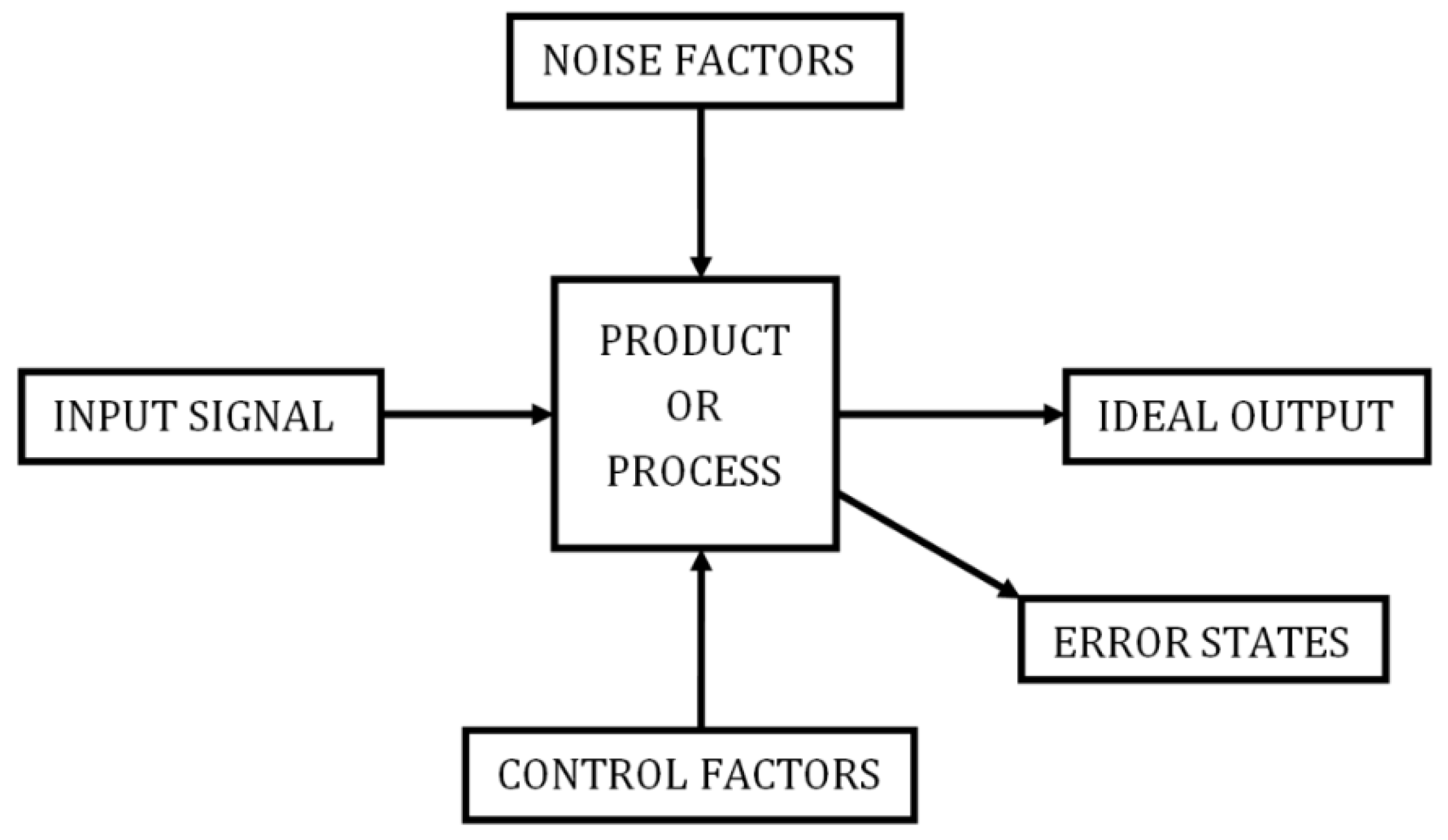
3.1. Creating P-Diagram for EV Battery Pack

The key steps taken to create the P-diagram are summarized below:
  • Identified the system boundaries—It is essential to define system boundaries before starting the procedure of creating a P-diagram. A boundary diagram displays various component blocks constituting the system. It also allows easy visualization of system interface enabling energy/information exchange with the environment. Hence, a boundary diagram is created through careful examination of existing battery packs (Tesla Model S, GM Chevrolet Volt, and Nissan Leaf) and the published literature.
  • Defined the input signal and the ideal response—Since, CNs highlight the important product characteristics while informing the product designers about “what needs to be done”, CNs were listed in the ideal response column of a P-diagram. In EVs, the combination of electrochemical cells or the battery pack receives an input signal from the EV driver in form of pedal force. The pedal force controls the throttle position, which in turn makes the electrochemical system respond by delivering power—continuous power and peak power, as and when required during the drive cycle. Noteworthy is that satisfying only basic functional requirements, i.e., delivering the power required during the drive cycle and meeting the standard safety requirements is not sufficient for a modular EV battery pack to be considered desirable. An EV user may also have several implicit expectations from it. Procedure adopted for identifying these requirements will be discussed in Section 4.1.
  • Separated the noise factors from the control factors—Transformation of throttle position to battery output power can be maximized by controlling the interaction of the battery pack with the external environment through various system interfaces. Control over system interactions can be gained by distinguishing parameters that have a direct impact on system output and adjusting those that lie within its boundary. For example, effect of temperature on thermal performance of the battery cells can be reduced by selecting and installing a suitable thermal management system in the battery pack. Also, battery cell size or layout or packaging clearance can all be modified to make a battery pack more compact, lightweight, and thermally stable while increasing the ease of manufacturing and ease of service at the same time.
  • Established the potential error states—Error states portray the way system failure would be physically noticed in a real-world application. Physical contact between neighboring cells and production of smoke or odor during battery operation are some of the examples of potential failure modes for a battery pack in an EV. Other physical indicators defining the state of failure for a battery cell were identified through literature review. They are listed in Table 1 [38]. The table also identifies fundamental physical, chemical, mechanical, or electrical stress inducing mechanisms that may cause an electrochemical cell to fail along with potential failure cause or force driving the battery cell failure.

3.2. Discovering the Relationship of Control Factors with the CNs

A QFD analysis is typically conducted through four inter-linked matrices, where each of the four matrices is generated in multiple steps. A detailed description of these steps can be found in [39,40]. Among these, matrix/stage 1 is strategically the most important phase as the CNs are translated to the PTRs during this stage. It has thus been reported that substantial benefits can be achieved by implementing just the first phase of QFD system [41].
Accordingly, emphasis of the present study is also on the first phase of QFD, commonly known as the House of Quality (HoQ). More specifically, objective of the following sections is limited to identification, understanding and evaluation of the relationship between different CNs and PTRs of an EV battery pack while assessment of the correlations among various PTRs will form a part of a future study. Strength of these relationships was estimated from literature surveys, findings of which are validated through a group decision making approach. In our case, the success of this approach is ensured by inter-disciplinary nature of the experts’ panel guiding the decision-making process.

4. Procedures

Methods adopted for acquiring intermediary information required for construction of the P-diagram and the HoQ are presented in this section.

4.1. Determining CNs through Expert Panel Consultation

There are several ways including minimax deviation [42], minimum mean-square error method [43] and Delphi method [44] to determine what a customer wants as an output of the system. The Delphi method, which is a structured communication technique for discovering expert opinions and consensus building on a subject, is adopted in the present study because of its simplicity and ease of implementation.
As a part of this method, an expert panel comprising of fifteen leading professionals from the automotive sector is created. Details of the panel are presented in Table 2. It can be seen from this table that collectively, the panel had vast experience in the areas of battery pack design, manufacturing, vehicle light weighting, structural analysis, project management and quality improvement. Confidential one-to-one discussions were conducted with these experts. Main theme of the discussion was “expected features and quality requirements from the battery pack of their targeted application”. Their opinion on EV battery pack performance barriers and preferred strategy for designing a robust battery pack were also recorded. A comprehensive list of implicit customer requirements for EV battery pack is thus developed based on the expert’s opinion.

4.2. System Boundaries for EV Battery Pack

In case of an EV battery pack, which is essentially a parallel and series combination of multiple electrochemical cells, interactions with the external environment can happen through several interfaces identified in Figure 3.
The figure shows a chemical system in form of a combination of battery cells trading energy with its environment via various interfaces. A brief description of each of these interfaces is provided underneath.
A. 
Mechanical—represents all the mechanical design features such as cell spacers, damping pads, pressure relief or exhaust valves, seals/gasket that have been integrated in to the battery pack mainly for safety reasons.
B. 
Structural—A battery pack needs to be contained in a case and a cover to prevent it from the effect of humidity, dirt, and other environmental factors. Besides, proper vibration isolation and high crash-worthiness is also necessary. Consequently, structural features such as end-plates, tie-rods, cross-members are provided to function as protective members in the battery pack.
C. 
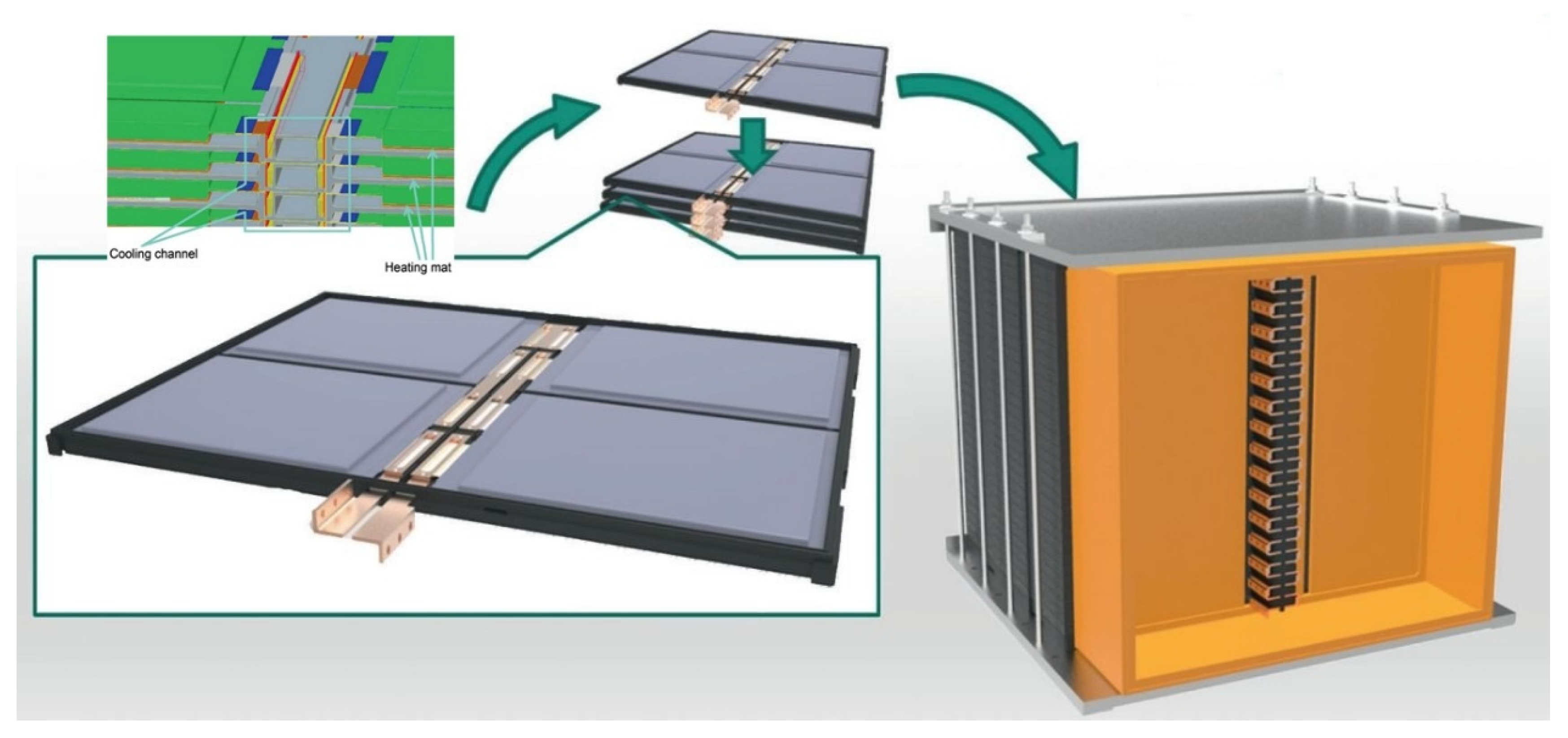
Thermal—Control of Li-ion battery cell temperature between 25 °C and 30 °C and a uniform thermal distribution across the Li-ion battery pack is required for maximizing its energy capacity. To ensure this, a thermal management system (TMS) including a fluid transfer duct, cooling/heating fluid, insulation coating, auxiliary systems such as fans, pumps, heat exchangers is usually integrated with the battery pack.
D. 
Electrical—Battery pack generates current at a certain voltage to meet power requirements of an EV drive-cycle. This power gets transferred through an electrical circuit comprising of bus bar and cables, fuse, circuit breakers, contactors, and relays to the EV driveline.
E. 
Control Systems—Battery management system, sensors for measuring voltage, current, pressure, temperature and humidity are employed to monitor and regulate the state of battery pack.
F. 
Support—An EV battery pack is generally commissioned in the vehicle through mounting brackets and axle that assists in achieving the required degree of vibration isolation for a reliable operation. Support from chassis and vehicle body increases the overall crash-worthiness. Similarly, the vehicle floor panel and seats provide isolation of the high voltage components from the passenger cabin.

4.3. Characterisation of the Impact of Noise Factors on EV Performance

In this study, the noise factors and the control factors are mainly identified via a detailed review of the published literature. Subsequently, the findings are discussed with the expert panel. Final categorization is based on the consensus developed among the panel members.
A. 
Customer Usage—Driving range of an EV depends on the speed and acceleration characteristics of each trip. Trips with faster acceleration or including ascend over high altitude grades will demand more kilowatts per kilometer travelled. Moreover, studies about the driving patterns of EVs reflect that unlike conventional ICE vehicles, EVs are rarely driven in high speed motorway conditions and more in rural and urban environment. Consequently, battery packs of EVs that are driven mainly in rural or urban terrain are exposed to a more strenuous life in comparison to those driven over a more traditional composition of road surfaces [45,46].
B. 
Vibrations—Driving induces vibration profiles concentrated in 1 Hz–25 Hz frequency range with as much as 10% higher energy levels. Pouch cells which are more common in EV applications are more prone to localization of vibrational forces. This can in turn cause sharp increases in local stress levels in battery pack resulting in their mechanical and electromechanical failure [47].
C. 
Ambient Temperature—Another factor that can have a significant effect on available energy and cycle life of Li-ion batteries is the battery cell temperature. It has been found that with each degree increase in battery cell temperature in the operating range of 30 °C and 40 °C, the cycle life of batteries reduces by approximately two months [48]. Moreover, an estimate by General Motors indicate that an EV can lose up to 85% of its range at sub-zero temperature if no thermal management system is used to regulate it [49]. Besides, the rate of self-discharge is also dependent on the storage temperature. Energy capacity of a battery also degrades in response to ambient temperature and other factors throughout its cycle life [50].
D. 
Cell-to-Cell Variations—Accidental and practically unavoidable physical and chemical variations among battery cells have a far-reaching effect on the structural dynamics of the battery pack. These random variations lead to confinement of vibrational energy to a small portion of the cell structure [47]. It is, therefore, vital to minimize any random cell-to-cell variations to be able to define battery performance with reliability as each battery cell will react in a peculiar manner to stimuli received from other sources of disturbance such as customer usage or external environment.
E. 
Auxiliary Load—System interactions such as heat leakage from different electro-mechanical systems, chassis vibrations, electrical interference, auxiliary loads such as cabin heating/cooling, power steering, air compressors affect the quality of output from battery pack. For example, researchers from NREL (National Renewable Energy Laboratory) have confirmed that depending upon the ambient environment, power requirements for managing the cabin thermal loads can decrease the driving range of a plug-in EV by 35% to 50% [51].
It should be recalled that the production costs for eliminating these sources of variation in battery cells can be very large. It must therefore be the priority of any battery pack designer to make the pack insensitive to such variations. Also, changes over time may not be noticeable in a short time-span but it is critical to reduce their influence on battery cycle life for the pack to remain on-board diagnostic compliant.

4.4. Determination of Technical Characteristics

PTRs are generally used to assess product’s ability in meeting the CNs and must therefore be specified in measurable terms. In addition, they should not be design specific and have a general significance. Benchmarks for evaluating EV battery pack performance are established by United States Advanced Battery Consortium (USABC). They are presented in Table 3.
Consultation with various experts contacted during this investigation reveal that in addition to responding to pedal force, which controls the throttle position, by delivering power to an EV the battery pack must also be:
Lightweight
Compact packaging
Ergonomic
Structurally rigid
Swappable
Configurable and Scalable
Thermally stable
Impact resistant
Fire-proof
Ease of manufacturing
Ease of service
Low cost
The following sub-sections will seek to relate them to different technical characteristics and other factors that may influence the performance of the modular EV battery pack.

4.4.1. Light Weight

Total weight of EV battery packs can be reduced by replacing their primary component, i.e., the battery cells with cells made of novel materials that possess greater gravimetric capacity ( mAh / g ) or demonstrate a higher operating voltage than traditional active materials [53,54]. However, increase in gravimetric density of electrode materials cannot be scaled linearly to be reflected as nominal capacity of commercial battery cells due to the non-negligible weight of inactive cell components. It has been reported that the active material contained in commercial Li-ion battery cells accounts for only 55% of their total weight [55]. In contrast, a thin copper foil, added in the cell assembly to function as a current collector at the anode, can make up to 10% of the total cell weight [56]. Figure 4 shows comparison of mass distribution for different components of a high power and a high energy battery cell.
Significant improvements in gravimetric density of Li-ion cells can thus be achieved by introducing lightweight replacements for inactive electrode components such as binder, separator, current collectors, and cell housing.
Reports show that areal capacities for anode materials that have high gravimetric capacities, e.g., double walled Si-nanotube is approximately seventeen times less than the areal capacity for a graphite anode (4.1 mAh / cm 2 ) [58]. It is equivalent to material loading of 0.1 mg / cm 2 . Low areal capacity results in addition of redundant weight in form of current collectors, separators, interconnectors etc. to a full cell construction. Non-uniform current distribution and localized active material utilization are some of the issues affecting performance of physically large battery cells. Inhomogeneous temperature gradient across the battery cell due to excessive localized material utilization during high power abstraction can result in permanent damage to battery cell and even push it into a state of thermal runaway [59]. Selecting battery cells with high areal capacities is thus crucial not just for developing a light-weight battery pack but for safety reasons as well.
The 24.2 kWh battery pack of VW e-Golf 2015 was designed using Li-ion pouch cells with nominal capacities of 25 Ah. Subsequently, the manufacturers chose to adopt 35 Ah pouch cells for the pack design and achieved an overall energy storage capacity of 35.8 kWh for the VW e-Golf 2017 without affecting the number of battery cells in the original pack. Similarly, BMW i3 team is slowly phasing out the 60 Ah pouch cells to make way for the 94 Ah pouch cells in their battery packs as the larger cells provide 50% higher energy storage capacity with in the same architectural space [60]. Primary reason for the observed shift in battery cell selection is that as the cell size, i.e., nominal capacity, increases the number of battery cells required for designing a battery pack of specified capacity reduces. Also, along with them the number of cell-interconnections and the quantity of cell protection circuits and wiring required for pack integration is proportionally decreased thus leading to a higher weight and volumetric efficiency. Other advantages of using larger cell size include lower assembly cost and ease of troubleshooting [61].

4.4.2. Compact Packaging

Studies have shown that small cylindrical cells can conform much easily to the available space and thus have a higher packing density than both the pouch and the prismatic cell types. In fact, packing densities for battery packs comprising of 18650-format battery cells, 26650-format battery cells and large prismatic cells have been reported as 47,524.75 cells / m 3 , 22,857.14 cells / m 3 and 416.6667 cells / m 3 , respectively. It has been further reported that while the packing density of the battery pack with 18650-format cells is 114 times more than that of the pack comprising large prismatic cells, the physical density of the former is only 1.5 times greater than that of the latter. Moreover, the packing density of a pouch cell is approximately 2 times lesser than that of a prismatic cell of similar nominal capacity mainly because of its smaller thickness and large surface area. It is, therefore, relatively easier to improve volumetric efficiency of the battery pack by packaging large quantities of smaller cylindrical cells in the available space than to use large prismatic or pouch cells [62].
Compactness of packaging design can also have an appreciable influence on thermal performance of a battery pack. Research shows that increasing the cell-to-cell spacing for a battery pack from 1 mm to 10 mm can lead to a loss of approximately 1 °C in the steady state cell core temperature, for all the three physical formats [63]. As per the NASA-Battery Safety Requirements document: JSC 20793 Rev C cell spacing is more critical for pack designs employing battery cells of gravimetric energy density greater than 80 Wh/kg. It has further been ascertained that to alleviate cell-to-cell heat propagation in the instance of a single cell failure or a thermal runaway event, a minimum spacing of 2 mm is required for cylindrical cell formats. In addition, a physical barrier between neighboring cells is required for the same reasons in battery packs that employ cell formats with side vents [64,65].

4.4.3. Ease of Manufacturing

Ease of manufacturing depends on manufacturing of battery cells rather than the pack itself. It requires using innovative and simple techniques for processing cheap aqueous electrode formulations. One of the suggested techniques involve reducing copper loss and the amount of other inactive components used per unit cell volume by fabricating ultra-thick electrodes with high active material loading. However, high mass loading can often lead to reduced charge transfer rates and increased internal stresses in electrode layer. Additionally, inhomogeneous electrolyte penetration and poor adhesion between dry films of an ultra-thick electrode and current collectors can result in sluggish transport kinetics [66]. Also, 3D micro-structured electrodes that demonstrate shorter diffusion lengths and reduced ohmic resistance are sometimes utilized for achieving higher power density and energy capacity. However, fabrication of 3D microstructures besides being expensive, also involves many complex processing steps whereas simple manufacturing methods with a minimum number of fabrication steps are generally preferred for commercialization [67].
Influence of manufacturing scale on cell production cost becomes significant if battery cell design is altered without increasing the annual production quantity. Contribution of material cost to total manufacturing cost increases as manufacturing scale is increased, leading to a substantial decrease in labor and capital costs per unit battery pack particularly at low production rates. As a result, larger cost benefits can be attained by increasing the manufacturing scale of battery packs for hybrid vehicles than pure EVs since the material costs constitute a smaller fraction of the total battery cost for the former, as seen from Figure 5.

4.4.4. Ease of Assembly

In accordance with the ISO Publicly Available Specification—ISO/PAS IEC abcd Part 1: Requirements on dimensions for lithium-ion cells for vehicle propulsion, both the electrical connection elements (contacts) are located on top side of the Li-ion pouch cells designed for high energy applications. On the other hand, for high power pouch cells one of the contacts is located at the top while the other contact is placed on the opposite side of the cells as seen from Figure 6 [68].
Extra clamping tools are thus required for assembly procedure of interconnections between high power pouch cells. This issue affects cylindrical battery cells as well because they too have electrical contacts on both ends. It also renders the external structure design more complex while increasing the wiring complexity and the assembly cost. In addition, punched holes on bare metal terminals of pouch cells are needed to connect them to the copper bus bar through screw and nut.
Comparatively, the assembly process of prismatic cells is highly simplified through a “Poka-yoke” feature included in the design of their male thread terminals. Consequently, only spring washers and nuts are needed to interconnect their terminals. Moreover, soft packaging of the pouch cells makes it necessary to employ special precautions and handling procedures to minimize any rough handling during the assembly of battery cells as it may lead to local stress development in the cell structure. Delamination of the composite electrode layers is also possible under situations of extreme shock or through continuous transmission of vibrations during operation. Additional structural members are hence required in packaging for pouch cells for exerting compressive force, to provide vibration isolation and to make them shock-resistant [69,70], which in turn incur extra assembly cost. As a result, cost of assembling one unit of pouch cell using mechanical fasteners in the year 2016 was reported to be USD 0.125 as opposed to USD 0.0692 for the prismatic cells [71].
EV battery packs are generally assembled manually, with the assembly cost being proportional to the number of battery cells, cell holders and interconnections and the type of battery management system (BMS) and TMS used. Accordingly, the cost of assembly for one unit of battery pack with 18,650 type battery cells (excluding BMS) has been calculated as USD 424.32 (assuming approximately 85 person hours at USD 5 per hour). In contrast, estimates indicate that it would cost only USD 3.46 with the process lasting less than 1 h to assemble a battery pack of equivalent capacity using large prismatic cells excluding BMS [57]. As such, more economical battery packs can be manufactured as the assembly process is significantly simplified and the total production time is considerably reduced by using large format battery cells.

4.4.5. Structural Stability

In the absence of adequate compressive force needed to maintain a uniform contact, delamination of electrode layers occurs in pouch cells and prismatic cells, which affects their performance and reliability. Delamination of the electrode layers can be avoided through usage of external structures that may include either hard plates stacked on each side of the battery cell or clamps made of thread rods. Although the stacking plate method provides significant advantage during manual assembly of battery packs, it is more expensive on a mass production basis. Also, holding clamps may make the pouch cells more vulnerable to mishandling during assembly process and to localized stress development due to unbalanced clamping force [71].
The solid structure created through metallic or rigid plastic casings typically used for the prismatic and the cylindrical battery cells prevents foreign objects such as nails from penetrating the electrochemical system. The metallic casings provide more tolerance to pressures generated inside the battery cell because of gas generation and venting; a safety feature missing from the pouch cells owing to their soft packaging.
Main structural issue with the prismatic cells is that their corners can be left vacant due to elliptical windings. It results in uneven pressure distribution in electrodes, but the problem can be alleviated by filling solid material in vacant corners. Table 4 compares different battery cell formats according to structural characteristics considered important from safety perspective.
Maintaining structural integrity of the battery pack during crash conditions is another challenge for EV designers. For this purpose, two packaging architectures—the “T-shaped” architecture and the “Floor” configuration are primarily utilized for EV battery packs.
The “T-shaped” architecture seen in Figure 7a is used in GM Chevrolet Volt. It enables the battery modules to be arranged inside the primary safe zone of the vehicle, i.e., the area beneath the rear passenger seats and extending along the tunnel between the two rows of seats. It prevents the battery pack from direct frontal impact and side impact loads through usage of vehicle structure as a crash barrier at the expense of interior cabin space and sometimes passenger comfort as well.
In contrast, the “Floor” configuration, used in Tesla Model S and Audi e-tron Sportback concept seen in Figure 7b, involves arranging the battery cells in a slab format under the vehicle floor. It maximizes the available cabin space to be used either by the vehicle occupants themselves or for storing their luggage. In addition, such configuration increases the vehicle stability during various driving maneuvers by lowering its center of gravity. However, it also reduces the ground clearance of the vehicle thus exposing the battery pack to dangers of ground or bottom impact [70].
Battery cells are traditionally protected against the bottom impact via metal or plastic shell casing enclosures in conjunction with module and battery pack housings and vehicle body structure including transverse cross members, doors and floor [69]. Furthermore, as floor panel can only resist impact from small stones on a gravel road, an armor made of 1 mm to 6 mm thick metallic sheet, with a monolithic or a sandwich structure or even their combination, is used as a protection against bottom impact. Polymeric coating is applied to it for rust protection. Research has shown that severity of the damage to the protective armor plate is affected by the tip radius of the impacting body, the distance of the indentation point to the nearest boundary of the battery module and the exponent of the power law hardening curve. It has further been reported that other thinner protective members of the battery pack rupture soon after the armor is breached thereby exposing the battery cells to damage from road debris and other sharp objects [75].
To restrict this damage to minimum, a multifunctional granular battery assembly (GBA) pack, in which the battery cells are organized in a bimodal packing arrangement along with collapsible and sacrificial metal tubes, has been proposed. GBA can function as an energy storage system and a stress control plus energy dissipation unit simultaneously. Simulation studies rate it as 2.6 times more effective than a metal foam structure of equivalent density in reducing the probability of battery pack failure during crash conditions. A reduction of over 5% in the head injury criterion of EVs due to the use of GBAs has also been observed as opposed to likelihood of head injury arising from an impact to an EV occupant employing traditional battery packs. However, disadvantages of employing GBA in place of a conventional battery pack include a decline of 35% and 13% in the volumetric capacity and gravimetric capacity of the vehicle, respectively. More importantly, the metal tubes of a GBA add approximately 3% to the gross vehicle weight that could influence not only EV driving range but also its rolling resistance [76].

4.4.6. Thermal Stability

It has been reported that it becomes increasingly difficult to transfer heat from/to a battery cell as the heat transfer area available per unit volume of battery cell decreases. Accordingly, a larger base area and a controllable thickness are preferential for pouch cells. Similarly, taller height and a smaller diameter are recommended to enable efficient heat dissipation through spiral wound cells. However, longer electron current path along axial direction could affect cell performance and shorten the cycle life. On the other hand, increasing the cell diameter in order to reduce the height of the cylindrical cell will impede radial heat transfer rate, which in turn would also have a negative effect on the cell performance [62]. Optimal cell size is thus chosen as per the module requirement.
A study investigating heat rejection properties of 10 Ah battery cell of pouch format (W: 73.35 mm, H: 163.40 mm, T: 10.60 mm), prismatic format (1865140) and cylindrical format (38120) reported their heat transfer areas per unit volume as 228.19 m−1, 156.17 m−1 and 105.26 m−1, respectively. Consequently, thermal management of cylindrical cells was found to be more difficult than the battery cells of other formats [71]. Insights gained from this study are offered in Table 5.
Moreover, liquid cooling technique has proved more effective at regulating battery cell temperatures within the recommended window and also at minimizing thermal gradients in large battery packs operating at high discharge rates [77]. Under this technique, a liquid coolant is passed through built-in mini-channels of a metallic plate kept in close contact with the battery cells. The plate generally has high thermal conductivity and a flat shape, which makes its application easy in case of battery packs made of pouch and prismatic cells. However, the same shape makes it difficult to transfer heat from cylindrical cells using a cold plate [78]. Inefficiency in heat transfer due to incompatible geometries and marginalized contact area can be removed via heat pipes or through phase change materials (PCMs). Heat pipes provide a compact cooling solution with high effective conductivity while PCMs enable a greater control over battery cell temperature. However, cost for heat pipes and low thermal conductivity of PCMs needs to be considered while selecting a suitable thermal management system for EV battery packs [62]. Recently, Arora et al. demonstrated that the issue of low thermal conductivity for PCMs can be addressed by using an inverted battery cell layout in construction of PCM-cooled battery packs [79]. Inverted cell arrangement promotes convective heat transfer in battery packs and has a positive effect on effective thermal conductivity of PCM-based TMSs.

5. Results and Discussion

5.1. Modified P-Diagram for an EV Battery Pack

A P-diagram showing the parameters affecting the ideal output of an EV battery pack along with the possible failure modes is presented in Figure 8. As every engineering system has certain efficiency and corresponding energy losses associated with it, a better design is one that can minimize these energy losses. These unwanted but inherent energy loss must however be documented in the P-diagram. Heat generated during battery cell operation would be a typical example of an inherent loss associated with EV battery packs.
The P-diagram illustrated in Figure 8 has therefore been modified to include this ever-present loss of energy. The modified P-diagram establishes conversion of a part of chemical and electrical energy to heat as an ineradicable phenomenon during discharging and charging of battery packs, respectively. It also acknowledges that no real system can be perfectly isolated. Hence, heat flow and thermal interactions between the adjacent battery cells or modules are bound to happen. If within the specified limits, it should be accepted as normal physical behavior leaving the battery designer to target the undesired side effects. Additionally, the noise factors are arranged according to their level of influence on the battery pack performance. The diagram allows envisioning all the factors involved in battery pack design and operation at the same time.

5.2. The House of Quality for EV Battery Pack

Figure 9 shows the HoQ constructed to illustrate the significance of relationships between each CN and PTR for an EV battery pack. Left wall or the “what” column of the HoQ matrix documents “voice of the customer” or features that an EV battery pack is expected to possess by its user. On the other hand, all the measurable technical characteristics identified as important for meeting the specified CNs, also called “How”, are collated in ceiling of the matrix. More importantly, strength of the relationship between the “whats” and the “hows” is presented in central part of the HoQ matrix.
Figure 9 is constructed while considering all potential customers including OEMs, production team, after sales department, government departments or policy makers, technicians/mechanics, EV driver and passengers. Equal weight is thus accorded to each CN in this exercise. The HoQ matrix can also be customized to target specific customer group, where different CNs are ranked to suit customer priorities.
Accurate scoring of these relationships is crucial for new product development process. Therefore, as mentioned previously in Section 3.2, representative strengths shown in this study are estimated based on data derived from synthesis of relevant literature and subsequently validated by group decision of expert’s panel. Symbols Ο , , and Δ are further used for denoting weak, moderate and strong correlation, respectively, while a blank space in the relationship matrix indicate lack of relationship between a CN and corresponding PTR.
Evidently, there are several parameters, namely cell size, casing material, battery pack location in the vehicle that can be regulated to optimize its performance and reliability. However, it is evident from the quality matrix and the preceding discussion that the two most important technical characteristics for an EV battery pack are packaging architecture and thermal management system. They both have an appreciable effect on mechanical modularity and thermal modularity of the battery pack architecture and thus warrant careful attention during early design stages.
Battery packs are designed by connecting multiple battery cells in a series-parallel combination. As a result, they can be rescaled simply by modifying the number of battery cells involved in this combination. However, as soon as a conventional, i.e., a forced-air or a liquid-cooling TMS is integrated with the electrical framework of the batteries; the battery pack loses its configurability. For example, if to meet the energy requirements for a certain application, more number of battery modules are needed to be added to the current pack architecture or if a few modules can be removed from it, piping/plumbing and the auxiliary equipment used in the existing battery thermal management system would then either be classified as over-designed or under-designed for the new application and thus have to be redesigned via procedure developed by Pesaran et al. [77].
It shall be recalled that the modular packs presented in Section 1.2 did not include a fully functional TMS. Although a TMS is required for managing large temperature spikes and maintaining proper thermal balance in the pack, added design complexity and unwanted parasitic load overshadow the benefits derived by installing a traditional TMS in the EV battery pack. As a result, different OEMs follow different design routes. Table 6 differentiates the OEMs that provide battery packs fitted with a liquid-cooled TMS in their EVs from those who do not. It is, therefore, imperative for a battery pack to have a modular TMS for it to retain its scalability and configurability.
Care should also be taken in mechanical/thermal design since mechanical connections in battery packaging architecture also act as heat transfer paths between bordering battery cells and modules. In other words, mechanical modularity is dependent on thermal modularity of the system as heat exchange between neighboring battery modules cannot be fully eliminated. Hence, thermal independence of adjoining battery cells must be ensured so that structural and mechanical design requirements can be satisfied for the modular battery pack.
A TMS capable of providing this functionality is presented in our recent publication [79]. It is designed using PCMs and thermoelectric circuits and puts negative parasitic load on the battery pack. More importantly, it is readily scalable and makes individual battery cells thermally independent of the adjacent cells.
The concept of thermal independence at cell-level for an EV battery pack design has a powerful benefit—to reduce or even eliminate the custom, vehicle-specific thermal analysis that accompanies system-level vehicle design process. If vehicle architecture successfully implements these thermal modularity concepts, then it does not matter where in the vehicle the module is placed. It would literally be thermally interchangeable due to its cell-level thermal independence; because a module designed like this could be placed anywhere in the vehicle and it would just work thermally. This would preclude the necessity for a system-level thermal analysis or at the very least drastically reduce its scope. Consequently, it would represent substantial savings in the non-recurring engineering associated with the thermal analysis of a particular vehicle. This also provides an opportunity to integrate innovation in the early product design stages and embed the supposed inherent robustness into the product design.

6. Conclusions

Mass production of battery cells is one way to regulate high manufacturing costs of EV battery packs and improve global market capturing rate of EVs. Previous research has established that variability has a negative influence on mass producibility of any system. Additionally, the pool of variables that can affect cycle life, performance and safety characteristics of Li-ion battery cells is large.
In this paper, we present a systematic framework that enables battery pack designers to conceptually analyze elements of this pool, develop a clear understanding of customer needs, and identify factors that can be optimally adjusted to build a reliable battery pack that meets various customer requirements in entirety. A value-based product development technique, commonly known as robust design methodology (RDM), is applied for evaluation of design aspects related to battery cell type and size, packaging architecture, thermal management solution etc. of modular EV battery pack.
Through the application of RDM a major technological limitation of battery packs’ design is revealed. It is discovered that the mechanical design and the thermal design of battery packs are essentially interrelated; meaning that neglecting either of the two would compromise reliability of the battery pack. Also, mechanical/structural connections in battery packaging act as heat transfer paths. Thermal paths in a module-level design must therefore be adequately isolated after considering all mechanical hard points and connections. More importantly, it is found that piping/plumbing along with the auxiliaries used in conventional liquid cooling or forced-air cooling systems limit configurability and scalability of the battery pack. It is thus established that choices concerning selection of thermal management strategy and packaging design for the EV battery pack are crucial for successful implementation of modular battery pack architecture. In other words, designing a modular thermal management system is a pre-requisite for designing a reliable yet modular battery pack. A TMS involving PCMs and thermoelectric devices may prove useful in meeting these design goals.

Author Contributions

S.A. proposed the study, performed the research duties, conducted the interviews, analysed the data and other information. Also, he was responsible for writing the manuscript and other activities involved in the publishing process. A.K. and W.S. helped in putting together the experts’ panel and supervised the overall project. In addition, A.K. was responsible for securing the funding.

Funding

This work was financially supported by the Cooperative Research Centre for Advanced Automotive Technology (AutoCRC), Australia through a block grant for the project titled: Battery Charge, Mechanical and Thermal Management System Development (1–112).

Acknowledgments

We are thankful to various experts, namely, Mehran Motamed Ektesabi, Gary White, Ambarish Kulkarni, Alireza Tashakori, Himani Mazumdar, Arnaldo Sanchez, Tim Olding, Antonio Lione, Andrew Miller, Mark Cleave, Fengxian He, Parisa Amiribavandapour, Khay See, Jason Miller, Louisa De Vries and Xuidong Xui who spoke to us at length on various technical subjects during this study.

Conflicts of Interest

The authors declare no conflicts of interest.

References

  1. Pierpaolo Cazzola, M.G.; Teter, J.; Yi, W. Global EV Outlook 2016—Beyond One Million Electric Cars; International Energy Agency: Paris, France, 2016. [Google Scholar]
  2. Stevenson, M. Lithium-Ion Battery Packs Now $209 Per KWh, Will Fall to $100 by 2025: Bloomberg Analysis. Green Car Reports. 2017. Available online: greencarreports.com/news/1114245_lithium-ion-battery-packs-now-209-per-kwh-will-fall-to-100-by-2025-bloomberg-analysis (accessed on 26 February 2018).
  3. Tie, S.F.; Tan, C.W. A review of energy sources and energy management system in electric vehicles. Renew. Sustain. Energy Rev. 2013, 20, 82–102. [Google Scholar] [CrossRef]
  4. Vorrath, S. Electric vehicle boom driving EVs to 35% new car sales in Asia by 2040. RenewEconomy. 2016. Available online: reneweconomy.com.au/electric-vehicle-boom-driving-evs-35-new-car-sales-asia-2040/ (accessed on 3 March 2018).
  5. Trigg, T.; Telleen, P.; Boyd, R.; Cuenot, F.; D’Ambrosio, D.; Gaghen, R.; Gagné, J.F.; Hardcastle, A.; Houssin, D.; Jones, A.R.; et al. Global EV Outlook: Understanding the Electric Vehicle Landscape to 2020; International Energy Agency: Paris, France, 2013. [Google Scholar]
  6. Han, H.; Park, H.; Kil, K.C.; Jeon, Y.; Ko, Y.; Lee, C.; Kim, M.; Cho, C.-W.; Kim, K.; Paik, U.; et al. Microstructure control of the graphite anode with a high density for Li ion batteries with high energy density. Electrochim. Acta 2015, 166, 367–371. [Google Scholar] [CrossRef]
  7. Lu, J.; Chang, Y.-L.; Song, B.; Xia, H.; Yang, J.-R.; Lee, K.S.; Lu, L. High energy spinel-structured cathode stabilized by layered materials for advanced lithium-ion batteries. J. Power Sources 2014, 271, 604–613. [Google Scholar] [CrossRef]
  8. Sun, X.; Zhang, X.; Huang, B.; Zhang, H.; Zhang, D.; Ma, Y. (LiNi0.5Co0.2Mn0.3O2 + AC)/graphite hybrid energy storage device with high specific energy and high rate capability. J. Power Sources 2013, 243, 361–368. [Google Scholar] [CrossRef]
  9. Wang, G.; Ma, Z.; Shao, G.; Kong, L.; Gao, W. Synthesis of LiFePO4@carbon nanotube core–shell nanowires with a high-energy efficient method for superior lithium ion battery cathodes. J. Power Sources 2015, 291, 209–214. [Google Scholar] [CrossRef]
  10. Zhou, G.; Li, L.; Ma, C.; Wang, S.; Shi, Y.; Koratkar, N.; Ren, W.; Li, F.; Cheng, H.-M. A graphene foam electrode with high sulfur loading for flexible and high energy Li-S batteries. Nano Energy 2015, 11, 356–365. [Google Scholar] [CrossRef]
  11. Eroglu, D.; Ha, S.; Gallagher, K.G. Fraction of the theoretical specific energy achieved on pack level for hypothetical battery chemistries. J. Power Sources 2014, 267, 14–19. [Google Scholar] [CrossRef]
  12. Cheng, H.; Scott, K. Improving performance of rechargeable Li-air batteries from using Li-Nafion® binder. Electrochim. Acta 2014, 116, 51–58. [Google Scholar] [CrossRef]
  13. Li, L.; Fu, Y.; Manthiram, A. Imidazole-buffered acidic catholytes for hybrid Li–air batteries with high practical energy density. Electrochem. Commun. 2014, 47, 67–70. [Google Scholar] [CrossRef]
  14. Lu, X.; Lemmon, J.P.; Kim, J.Y.; Sprenkle, V.L.; Yang, Z. High energy density Na–S/NiCl2 hybrid battery. J. Power Sources 2013, 224, 312–316. [Google Scholar] [CrossRef]
  15. Wu, M.; Liu, M.; Long, G.; Wan, K.; Liang, Z.; Zhao, T.S. A novel high-energy-density positive electrolyte with multiple redox couples for redox flow batteries. Appl. Energy 2014, 136, 576–581. [Google Scholar] [CrossRef]
  16. Watanabe, C. Why battery cost could put the brakes on electric car sales. Climate Changed. Bloomberg Technology. 2017. Available online: bloomberg.com/news/articles/2017-11-28/electric-cars-need-cheaper-batteries-before-taking-over-the-road (accessed on 21 March 2018).
  17. Nykvist, B.; Nilsson, M. Rapidly falling costs of battery packs for electric vehicles. Nat. Clim.Chang. 2015, 5, 329–332. [Google Scholar] [CrossRef] [Green Version]
  18. US Department of Energy. EV Everywhere Grand Challenge Blueprint 2013—Drive More Electric Miles by 2022; US Department of Energy: Washington, DC, USA, 2013.
  19. Dinger, A.; Martin, R.; Mosquet, X.; Rabl, M.; Rizoulis, D.; Russo, M.; Sticher, G. Batteries for Electric Cars: Challenges, Opportunities, and the Outlook to 2020; Boston Consulting Group: Boston, MA, USA, 2010. [Google Scholar]
  20. Chang, T.-R.; Wang, C.-S.; Wang, C.-C. A systematic approach for green design in modular product development. Int. J. Adv. Manuf. Technol. 2013, 68, 2729–2741. [Google Scholar] [CrossRef]
  21. Fromm, P.; Drews, P. Modular, Service-Oriented Design and Architecture of Smart Vehicles for Short Distance Person and Freight Transport. In Proceedings of the 24th Annual Conference of the IEEE Industrial Electronics Society (IECON ’98), Aachen, Germany, 31 August–4 September 1998; ISBN 0780345037. [Google Scholar]
  22. Yang, W.M.; Chou, S.K.; Chua, K.J.; Li, J.; Zhao, X. Research on modular micro combustor-radiator with and without porous media. Chem. Eng. J. 2011, 168, 799–802. [Google Scholar] [CrossRef]
  23. Rothgang, S.; Baumhöfer, T.; van Hoek, H.; Lange, T.; De Doncker, R.W.; Sauer, D.U. Modular battery design for reliable, flexible and multi-technology energy storage systems. Appl. Energy 2015, 137, 931–937. [Google Scholar] [CrossRef]
  24. Baldwin, C.Y.; Clark, K.B. Design Rules; MIT Press: Cambridge, MA, USA, 1999. [Google Scholar]
  25. Hwang, B.C.; Fernandez Jose, M.; Meadows, V.; Thomas, S.; Amero Willard, F. 5534366 Modular battery pack. J. Power Sources 1997, 67, 356. [Google Scholar] [CrossRef]
  26. Valence batteries. Valence Technology: The First Scalable Large Lithium Ion Battery Pack; Lithium Werks: Austin, TX, USA, 2016; Available online: lithiumwerks.com/resources/case-studies/case-study-motive-high-voltage-traction-battery-for-railway/ (accessed on 2 April 2018).
  27. Schmid, A. Modular Li-Ion Battery Concept; Karlsruhe Institute of Technology: Karlsruhe, Germany, 2013. [Google Scholar]
  28. Arvidsson, M.; Gremyr, I.; Hasenkamp, T. An operationalization of robust design methodology. In Proceedings of the 10th QMOD Conference Quality Management and Organiqatinal Development Our Dreams of Excellence, Helsingborg, Sweden, 18–20 June 2007; Linköping University Electronic Press: Linköping, Sweden, 2008. [Google Scholar]
  29. Doltsinis, I.; Kang, Z. Robust design of structures using optimization methods. Comput. Methods Appl. Mech. Eng. 2004, 193, 2221–2237. [Google Scholar] [CrossRef]
  30. Goodenough, J.B.; Abruna, H.; Buchanan, M. Basic research needs for electrical energy storage. Report of the basic energy sciences workshop for electrical energy storage April 2–4, 2007. Energy 2007, 5429. [Google Scholar] [CrossRef]
  31. Tarascon, J.-M.; Armand, M. Issues and challenges facing rechargeable lithium batteries. Nature 2001, 414, 359–367. [Google Scholar] [CrossRef] [PubMed]
  32. Arvidsson, M.; Gremyr, I. Principles of robust design methodology. Qual. Reliab. Eng. Int. 2008, 24, 23–35. [Google Scholar] [CrossRef]
  33. Gremyr, I.; Siva, V.; Raharjo, H.; Goh, T.N. Adapting the robust design methodology to support sustainable product development. J. Clean. Product. 2014, 79, 231–238. [Google Scholar] [CrossRef]
  34. Arora, S.; Shen, W.; Kapoor, A. Designing a Robust Battery Pack for Electric Vehicles Using a Modified Parameter Diagram; SAE Technical Paper 2015-01-0041; SAE International: Melbourne, Australia, 2015. [Google Scholar]
  35. Chen, W.; Allen, J.K.; Tsui, K.-L.; Mistree, F. A procedure for robust design: Minimizing variations caused by noise factors and control factors. J. Mech. Des. 1996, 118, 478–485. [Google Scholar] [CrossRef]
  36. Vairaktarakis, G.L. Optimization tools for design and marketing of new/improved products using the house of quality. J. Oper. Manag. 1999, 17, 645–663. [Google Scholar] [CrossRef]
  37. Park, T.; Kim, K.J. Determination of an optimal set of design requirements using house of quality. J. Oper. Manag. 1998, 16, 569–581. [Google Scholar] [CrossRef]
  38. Hendricks, C.; Williard, N.; Mathew, S.; Pecht, M. A failure modes, mechanisms, and effects analysis (FMMEA) of lithium-ion batteries. J. Power Sources 2015, 297, 113–120. [Google Scholar] [CrossRef] [Green Version]
  39. Chan, L.-K.; Wu, M.-L. A systematic approach to quality function deployment with a full illustrative example. Omega 2005, 33, 119–139. [Google Scholar] [CrossRef]
  40. Bergquist, K.; Abeysekera, J. Quality function deployment (QFD)—A means for developing usable products. Int. J. Ind. Ergon. 1996, 18, 269–275. [Google Scholar] [CrossRef]
  41. Govers, C.P. What and how about quality function deployment (QFD). Int. J. Product. Econ. 1996, 46, 575–585. [Google Scholar] [CrossRef]
  42. Li, Y.L.; Chin, K.S.; Luo, X.G. Determining the final priority ratings of customer requirements in product planning by MDBM and BSC. Expert Syst. Appl. 2012, 39, 1243–1255. [Google Scholar] [CrossRef]
  43. Jiang, H.M.; Kwong, C.K.; Ip, W.H.; Wong, T.C. Modeling customer satisfaction for new product development using a PSO-based ANFIS approach. Appl. Soft. Comput. J. 2012, 12, 726–734. [Google Scholar] [CrossRef]
  44. Hsu, C.-C.; Sandford, B.A. The Delphi technique: Making sense of consensus. Pract. Assess. Res. Eval. 2007, 12, 1–8. [Google Scholar]
  45. Kulkarni, A.; Kapoor, A.; Arora, S. Battery Packaging and System Design for an Electric Vehicle; SAE Technical Paper 2015-01-0063; SAE International: Melbourne, Australia, 2015. [Google Scholar]
  46. Hooper, J.M.; Marco, J. Characterising the in-vehicle vibration inputs to the high voltage battery of an electric vehicle. J. Power Sources 2014, 245, 510–519. [Google Scholar] [CrossRef]
  47. Hong, S.-K.; Epureanu, B.I.; Castanier, M.P. Parametric reduced-order models of battery pack vibration including structural variation and prestress effects. J. Power Sources 2014, 261, 101–111. [Google Scholar] [CrossRef]
  48. Chacko, S.; Chung, Y.M. Thermal modelling of Li-ion polymer battery for electric vehicle drive cycles. J. Power Sources 2012, 213, 296–303. [Google Scholar] [CrossRef]
  49. Alaoui, C.; Salameh, Z.M. A novel thermal management for electric and hybrid vehicles. IEEE Trans. Veh. Technol. 2005, 54, 468–476. [Google Scholar] [CrossRef]
  50. Neubauer, J.; Wood, E. The impact of range anxiety and home, workplace, and public charging infrastructure on simulated battery electric vehicle lifetime utility. J. Power Sources 2014, 257, 12–20. [Google Scholar] [CrossRef]
  51. Kambly, K.R.; Bradley, T.H. Estimating the HVAC energy consumption of plug-in electric vehicles. J. Power Sources 2014, 259, 117–124. [Google Scholar] [CrossRef]
  52. Brodd, R.J. Batteries for Sustainability: Selected Entries from the Encyclopedia of Sustainability Science and Technology; Springer Science & Business Media: Berlin, Germany, 2012. [Google Scholar]
  53. Marinaro, M.; Weinberger, M.; Wohlfahrt-Mehrens, M. Toward pre-lithiatied high areal capacity silicon anodes for Lithium-ion batteries. Electrochim. Acta 2016, 206, 99–107. [Google Scholar] [CrossRef]
  54. Liang, B.; Liu, Y.; Xu, Y. Silicon-based materials as high capacity anodes for next generation lithium ion batteries. J. Power Sources 2014, 267, 469–490. [Google Scholar] [CrossRef]
  55. Yehezkel, S.; Auinat, M.; Sezin, N.; Starosvetsky, D.; Ein-Eli, Y. Bundled and densified carbon nanotubes (CNT) fabrics as flexible ultra-light weight Li-ion battery anode current collectors. J. Power Sources 2016, 312, 109–115. [Google Scholar] [CrossRef]
  56. Hu, L.; Choi, J.W.; Yang, Y.; Jeong, S.; La Mantia, F.; Cui, L.F.; Cui, Y. Highly conductive paper for energy-storage devices. Proc. Natl. Acad. Sci. USA 2009, 106, 214900–214904. [Google Scholar] [CrossRef] [PubMed]
  57. Nelson, P.A.; Bloom, K.; I Dees, D. Modeling the Performance and Cost of Lithium-Ion Batteries for Electric-Drive Vehicles; Argonne National Laboratory (ANL): Argonne, IL, USA, 2011.
  58. Kim, J.S.; Hwang, T.H.; Kim, B.G.; Min, J.; Choi, J.W. A lithium-sulfur battery with a high areal energy density. Adv. Funct. Mater. 2014, 24, 5359–5367. [Google Scholar] [CrossRef]
  59. Kim, U.S.; Shin, C.B.; Kim, C.-S. Modeling for the scale-up of a lithium-ion polymer battery. J. Power Sources 2009, 189, 841–846. [Google Scholar] [CrossRef]
  60. Arora, S.; Shen, W.; Kapoor, A. Neural network based computational model for estimation of heat generation in LiFePO4 pouch cells of different nominal capacities. Comput. Chem. Eng. 2017, 101, 81–94. [Google Scholar] [CrossRef]
  61. Pesaran, A.A.; Kim, G.-H.; Keyser, M. Integration issues of cells into battery packs for plug-in and hybrid electric vehicles. In Proceedings of the Hybrid and Fuel Cell Electric Vehicle Symposium on EVS-24 International Battery, Stavanger, Norway, 13–16 May 2009. [Google Scholar]
  62. Arora, S. Design of a Modular Battery Pack for Electric Vehicles. Ph.D. Thesis, Swinburne University of Technology, Melbourne, Australia, 2017. [Google Scholar]
  63. Coleman, B.; Ostanek, J.; Heinzel, J. Reducing cell-to-cell spacing for large-format lithium ion battery modules with aluminum or PCM heat sinks under failure conditions. Appl. Energy 2016, 180, 14–26. [Google Scholar] [CrossRef] [Green Version]
  64. Jeevarajan, J.; Lopez, C.; Orieukwu, J. Can Cell to Cell Thermal Runaway Propagation Be Prevented in a Li-Ion Battery Module; NASA: Washington, DC, USA, 2014.
  65. Jeevarajan, J.; Orieukwu, J.; Lopez, C. Preventing cell-to-cell thermal runaway in lithium-ion battery modules. In NASA Tech Briefs; NASA: Washington, DC, USA, 2016. [Google Scholar]
  66. Dittmann, J.; Willenbacher, N. Micro structural investigations and mechanical properties of macro porous ceramic materials from capillary suspensions. J. Am. Ceram. Soc. 2014, 97, 3787–3792. [Google Scholar] [CrossRef]
  67. Bitsch, B.; Gallasch, T.; Schroeder, M.; Börner, M.; Winter, M.; Willenbacher, N. Capillary suspensions as beneficial formulation concept for high energy density Li-ion battery electrodes. J. Power Sources 2016, 328, 114–123. [Google Scholar] [CrossRef]
  68. International Organization for Standardization (ISO). ISO/PAS 16898: 2012 Electrically Propelled Road Vehicles—Dimensions and Designation of Secondary Lithium-Ion Cells ISO/TC 22/SC 37 Electrically Propelled Vehicles; ISO: London, UK, 2012. [Google Scholar]
  69. Arora, S.; Shen, W.; Kapoor, A. Review of mechanical design and strategic placement technique of a robust battery pack for electric vehicles. Renew. Sustain. Energy Rev. 2016, 60, 1319–1331. [Google Scholar] [CrossRef]
  70. Arora, S.; Kapoor, A. Mechanical design and packaging of battery packs for electric vehicles. In Behaviour of Lithium-Ion Batteries in Electric Vehicles: Battery Health, Performance, Safety, and Cost; Pistoia, G., Liaw, B., Eds.; Springer International Publishing: Cham, Switzerland, 2018. [Google Scholar]
  71. Saw, L.H.; Ye, Y.; Tay, A.A.O. Integration issues of lithium-ion battery into electric vehicles battery pack. J. Clean. Product. 2016, 113, 1032–1045. [Google Scholar] [CrossRef]
  72. Andrea, D. Battery Management Systems for Large Lithium-Ion Battery Packs; Artech House: Boston, MA, USA, 2010; ISBN 9781608071043. [Google Scholar]
  73. Lamonica, M. GM: Without Software, Chevy Volt Is Stuck in Neutral. CNET News. 2010. Available online: www.cnet.com/news/gm-without-software-chevy-volt-is-stuck-in-neutral/ (accessed on 15 March 2018).
  74. Marino, A. Audi e-tron Sportsback concept Arctitecture of e-mobility. Drive and Ride. 2017. Available online: media.audiusa.com/en-us/releases/158 (accessed on 15 March 2018).
  75. Xia, Y.; Wierzbicki, T.; Sahraei, E.; Zhang, X. Damage of cells and battery packs due to ground impact. J. Power Sources 2014, 267, 78–97. [Google Scholar] [CrossRef]
  76. Kukreja, J.; Nguyen, T.; Siegmund, T.; Chen, W.; Tsutsui, W.; Balakrishnan, K.; Liao, H.; Parab, N. Crash analysis of a conceptual electric vehicle with a damage tolerant battery pack. Extrem. Mech. Lett. 2016, 9, 371–378. [Google Scholar] [CrossRef]
  77. Pesaran, A.A.; Burch, S.; Keyser, M. An approach for designing thermal management systems for electric and hybrid vehicle battery packs. In Proceedings of the Fourth Vehicle Thermal Management Systems Conference and Exhibition, London, UK, 24–27 May 1999. [Google Scholar]
  78. Rao, Z.; Wang, S. A review of power battery thermal energy management. Renew. Sustain. Energy Rev. 2011, 15, 4554–4571. [Google Scholar] [CrossRef]
  79. Arora, S.; Kapoor, A.; Shen, W. A novel thermal management system for improving discharge/charge performance of Li-ion battery packs under abuse. J. Power Sources 2018, 378, 759–775. [Google Scholar] [CrossRef]
Figure 1. Scalable battery solution developed by Karlsruhe Institute of Technology for automotive application [27].
Batteries 04 00030 g001
Figure 2. General layout of a P-diagram.
Batteries 04 00030 g002
Figure 3. System boundary interface for a battery pack [34].
Batteries 04 00030 g003
Figure 4. Comparison of mass distribution for different components of a high power and a high energy battery cell (based on data available from [57]).
Batteries 04 00030 g004
Figure 5. Comparison of overall manufacturing costs distribution (excluding pack integration system) for a high power and a high energy battery packs (based on data available from [57]).
Batteries 04 00030 g005
Figure 6. Position of electrical connection elements or contacts according to ISO Publicly Available Specification—ISO/PAS IEC abcd Part 1 for (a) high energy pouch cell and (b) high power pouch cell [68].
Batteries 04 00030 g006
Figure 7. Battery Packaging architectures (a) T-shaped architecture used in GM Chevrolet Volt [73] and (b) Floor architecture used in Audi e-tron Sportsback concept [74].
Batteries 04 00030 g007
Figure 8. Modified P-diagram for a modular EV battery pack.
Batteries 04 00030 g008
Figure 9. The House of Quality for an EV battery pack (Symbols, Ο , and Δ denote weak, moderate, and strong correlation, respectively).
Batteries 04 00030 g009
Table 1. Possible failure modes and mechanisms for a battery cell failure (based on the information available from [38]).
Observed EffectPotential Failure ModesPotential Failure CausesPotential Failure MechanismBattery ComponentLikelihoodSeverity
Reduction of power and capacityThickening of solid electrolyte interphase layerChemical side reactions between lithium, electrode, and solventChemical reduction reaction and depositionActive material coatings of Cathode and AnodeHighLow
Particle fractureIntercalation stressMechanical stressModerate
Reduced electrode porosityDimensional changes in electrodeMechanical degradationModerate
Increased charge transfer/diffusion resistancePitting corrosion of aluminumOvercharge of the batteryChemical corrosion reactionCathode current collectorLowModerate
Gas generationThermally driven electrode decompositionCathode active materialLowHigh
Decrease in lithium salt concentrationChemical side reactions between lithium, electrode, and solventChemical reduction reaction and depositionElectrolyte saltHighLow
Copper platingOver-discharge of the batteryChemical corrosion reaction and dissolutionAnode current collectorLowHigh
High joule heat generationInternal short-circuit between anode and cathodeExternal load on cellMechanical stressCasingLowHigh
Bloating of the casingExternal corrosive path between positive and negative leadsInadvertent shorting of the terminalsWear out through chemical corrosion reactionTerminals
Drastic voltage reductionHole in separatorDendrite formationMechanical damageSeparator
External crushing of the cell
Loss of conductivity between battery and host deviceSolder crackingCircuit disconnectThermal, mechanical fatigue and vibrationsCasingLowHigh
Inability to charge or discharge the batteryClosing of separator poresHigh internal cell temperatureThermally induced melting of separatorSeparatorLowHigh
Table 2. Details of the expert panel formed to identify implicit customer requirements for EV battery pack where, SUT refers to Swinburne University of Technology; UOW is University of Wollongong and GM stands for General Motors.
Member IDProfessional RoleOrganizationReasons for Selection
Member 1ProfessorSUT, AustraliaLeading EV R&D program in Australia for the past 10 years
Member 2Associate ProfessorSUT, AustraliaBattery pack modelling and design expert
Member 3Chief EngineerGM HoldenLead the vehicle electrification program (Commodore) at GM Holden. Worked as a consultant with several other EV enterprises
Member 4Specialist EngineerGM HoldenWas responsible for maintenance and safety on high voltage DC for the GM Volt program and setting up EV training at their Port Melbourne facility
Member 5Research DirectorAutoCRC Ltd.Mobilizing R&D activities for EV development in Australia and the Asia-Pacific Region under the Automotive Australia 2020 vision
Member 6Senior LecturerSUT, AustraliaTechnical leader—Electric Bus (eBus) development project for Malaysia
Member 7Research EngineerSUT, AustraliaPhD in EV motor drives. Headed the control systems development process for the eBus project at SUT
Member 8Research EngineerSUT, AustraliaDurability engineer with 8+ years of experience in automotive sector
Member 9Research EngineerSUT, AustraliaPhD in development of lightweight retro-fitted EVs
Member 10Senior LecturerSUT, AustraliaProduct Design Engineer with over 13 years of professional experience. PhD in lightweight EV drivetrain development
Member 11Research ScholarSUT, AustraliaExpertise in balancing of battery packs designed for EV applications
Member 12Post-doctoral ResearcherUOW, AustraliaExpertise in developing robust battery management control systems
Member 13Post-doctoral ResearcherUOW, AustraliaExpertise in developing high energy density Li-ion and Na battery cells
Member 14Manufacturing EngineerGM HoldenExperience of over 25 years in setting up manufacturing and assembly lines for large automotive project
Member 15Research ManagerFuturis AutomotiveOver 25 years of experience in manufacturing sector. Managed applied technology project worth more than $20 million. Filed two international patents application.
Table 3. USABC commercialization and long term performance goals for EV battery packs [52].
Parameter (Units) of Fully Burdened SystemMinimum Goals for CommercializationUSABC Long Term Goals
Specific energy—C/3 discharge rate, Wh/kg150200
Specific power—Discharge, 80% DOD/30 s, W/kg300400
Specific power—Regen, 20% DOD/10 s, W/kg150200
Energy density—C/3 discharge, Wh/L230300
Power density, W/L460600
Specific power to specific energy ratio2:12:1
Normal recharge time, hours64
Life, years1010
Cycle life—80% DOD, cycles10001000
Power & capacity degradation, % of rated spec2010
Selling price—25,000 units @ 40 kWh, $/kWh<150100
Table 4. Comparison of structural characteristics of different types of battery cells [72].
CriteriaSmall CylindricalLarge CylindricalPrismaticPouch
CasingMetalMetalSemi-hard plastic or MetalAluminum soft bag
ConnectionsWelded nickel or copper strips or platesThreaded stud for bolt or threaded hole for boltThreaded hole for boltTabs that are clamped, welded, or soldered
Retention against expansionInherent from cylindrical shapeInherent from cylindrical shapeRequires retaining plates at ends of batteryRequires retaining plates at ends of battery
Appropriateness for production runsGood: welded connections are reliableGoodExcellentExcellent
Field replacementNot possiblePossiblePossibleNot possible
DelaminationNot possibleNot possiblePossibleHighly possible
Compressive force holdingExcellentExcellentPoorExtremely Poor
Local stressNoNoNoYes
SafetyGood, integrated with PTCGood, integrated with PTCGood, integrated with PTCPoor, no safety features included
Heat shrink wrappingYesYesDepend on casing materialNo
Table 5. Comparison of different design characteristics of 19.2 kWh LiFePO 4 battery pack formed by using different types of battery cells [71].
ParameterBattery Cell Type
CylindricalSmall PrismaticPouch
186502665038120SmallLarge
Packing
Number of Cells4800240072060050600
Weight, kg 192196.8255.6171.0210172.5
Volume, m 3 (closed pack)0.1010.1050.1520.1310.1200.296
Packing density, cells / m 3 47,524.7522,857.144736.844580.153416.6672027.027
Interconnections Weight, kg 1.2170.62112.1110.241.16410.75
Cell holder weight, kg 81.640.812.2410.21.042.22
Physical density of battery pack, kg / m 3 2720.962268.771841.771461.3741768.033761.723
Cell cost, USD 3–11 7–18 20 20–40 150–400 20–40
Assembly of Single Cell
α, β orientation of cell360°, 0°360°, 0°360°, 0°360°, 360°360°, 360°360°, 360°
Cell handing and insertion time, s3.53.53.53.955.03.95
α, β orientation of interconnection180°, 180°180°, 180°180°, 180°180°, 180°180°, 180°180°, 180°
Interconnection handling plus insertion time/cell, s15.7215.7215.727.727.7215.72
α, β orientation of cell holder360°, 360°360°, 360°360°, 360°360°, 360°360°, 360°360°, 360°
Cell holder handling + insertion time, s7.47.47.47.47.49.4
Interconnection assembly time (two terminals), s373746.3629.7229.7260.74
Assembly cost per cell (assumed USD 5 per cell)0.08840.08840.1010.06780.06920.125
Electrical and Control
Terminal contact resistance, m Ω 0.40.40.60.60.60.8
Wiring Complexity+
Cell monitoring+
Reliability+++++
BMS cost+
Thermal Management
Heat generated from contact resistance, kJ / cycle (based on NEDC)2.0343.93519.60723.6747284.09734.090
Heat generated from the battery pack, kJ / cycle (based on NEDC)219.906215.670193.04215.440214.304218.991
Power consumption for cooling fan10.9670.3801.8376.7630.604
Complexity of design+++
Services and Maintenance
Faulty cell identification+
Ease of cell replacement and services+++
Uninterrupted operation if one unit cell fails+++++
Table 6. List distinguishing OEMs who prefer to use a conventional thermal management system for their EV battery packs from those who do not rely on it.
OEMS Using TMSOEMs not Using TMS
TeslaBYD
General MotorsNissan
FordVolkswagen
MercedesRenault
FiatMitsubishi

