Article

Three-Dimensional Physics-Based Circuit Modeling of Battery Incipient Faults in Microgrid Applications


Global College, Shanghai Jiao Tong University, Shanghai 200240, China
*
Author to whom correspondence should be addressed.
Batteries 2026, 12(8), 283; https://doi.org/10.3390/batteries12080283
Submission received: 14 June 2026 / Revised: 31 July 2026 / Accepted: 31 July 2026 / Published: 3 August 2026

Abstract

Battery condition directly affects the reliability, resilience, and safety of microgrids, making physically interpretable battery information an important input to situation awareness. In practical microgrid operation, battery monitoring commonly relies on terminal signals available to the supervisory energy-management layer. These signals do not directly reveal early internal degradation. This paper develops a three-dimensional physics-based circuit modeling framework for battery incipient fault information generation in microgrid situation awareness. A high-fidelity electrochemical model was employed offline as a virtual battery to generate controllable reference data that are difficult to obtain comprehensively through physical experiments. This virtual reference serves as the benchmark for validating the proposed circuit model. The three-dimensional physics-based circuit model then acts as the real-time modeling core, representing distributed electrochemical and thermal behavior at substantially lower computational cost. Across the evaluated discharge cases, the circuit model voltage outputs show that mean relative errors remain below 1.3% with respect to the virtual battery reference while achieving a tenfold reduction in mean solver time per step. The proposed model therefore provides an online-oriented foundation for extending battery-related situation awareness in microgrids from terminal-signal monitoring toward the model-informed representation of internal degradation.

1. Introduction

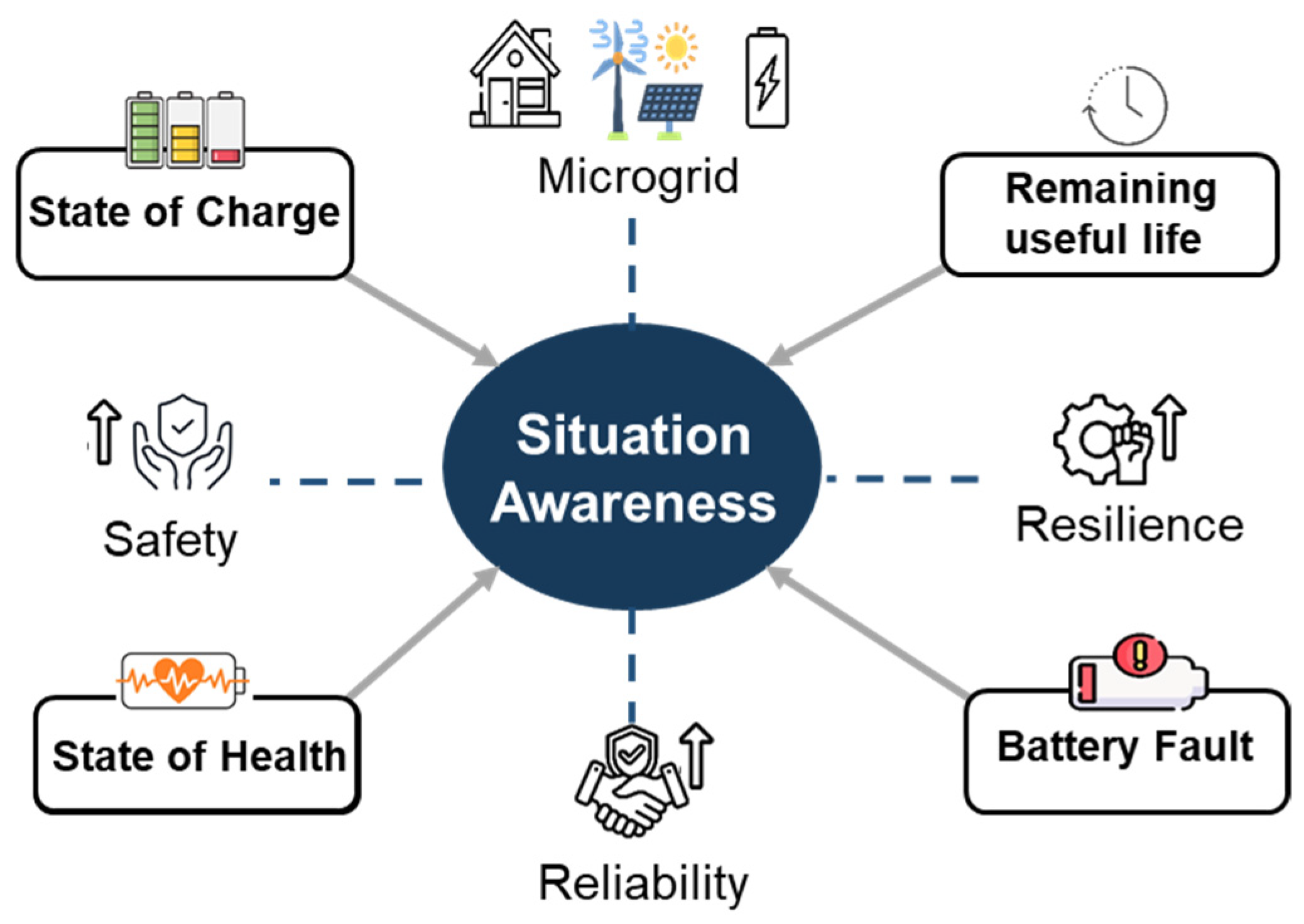
Battery energy storage systems (BESSs) are playing an increasingly important role in the global transition toward a sustainable electric society, with applications ranging from electric vehicles (EVs) to microgrids [1]. To optimize the management of these systems, situation awareness is witnessing accelerated adoption in networked microgrids, leveraging its advantages in real-time monitoring and predictive analysis [2]. In microgrids, effective situation awareness depends on accurate information from distributed components, including renewable generation, load demand, and particularly the operational condition of the BESS. As shown in Figure 1, battery plays a particularly important role because its situation awareness, which includes the monitoring and prediction of the state of charge (SOC), state of health (SOH), remaining useful life (RUL), and fault conditions, directly influences system safety, operational reliability, and resilience.
BESSs are predominantly composed of lithium-ion batteries (LIBs), which offer high energy density and efficient charging capability [3]. Nevertheless, they are vulnerable to slowly evolving internal mechanisms, including SEI growth [4] and metal dendrite growth [5]. The initial formation of a stable SEI is a normal electrochemical process. In this paper, SEI growth is treated as an incipient fault mechanism when persistent side reactions beyond the formation stage cause continued cyclable-lithium loss and interfacial-resistance growth. Metal dendrite growth denotes the degradation pathway initiated by metal dendrite growth on the negative-electrode surface. Continued development of these mechanisms contribute to capacity loss, internal short circuit, and thermal runaway [6].
At the microgrid operational level, BESSs are commonly monitored through externally measurable terminal voltage, current, temperature, and estimated SOC. These measurements support operational state tracking but do not directly observe SEI growth or metal dendrite growth states. Advanced cell-level monitoring approaches such as electrochemical impedance analysis can provide richer internal-state information. However, their additional sensing, excitation, calibration, or computational requirements can limit their routine availability at the microgrid energy management system [7].
To address this modeling need, we developed a three-dimensional (3D) physics-based circuit modeling framework for battery incipient faults. The 3D physics-based circuit model is the intended real-time core for representing distributed electrical and thermal behavior. A high-fidelity electrochemical–thermal virtual battery is used offline to provide spatially resolved temperature, potential, current-density, and degradation-state distributions under controlled operating and fault-relevant conditions. Its role is to supply mechanism-consistent reference information for development, numerical evaluation, and interpretation of the circuit model. The resulting cell-level indicators are intended as inputs for future microgrid situation awareness systems.
Building on the authors’ previous studies [8,9,10,11,12], the contributions of this paper are as follows: (1) this paper establishes a progressive physics-based circuit modeling framework for battery incipient fault information generation; (2) validates the proposed physics-based circuit model against the virtual battery, with cross-model evaluation focused on degradation-associated terminal-voltage behavior; and (3) demonstrates that the proposed framework achieves a balance between computational efficiency and physics-based representation for online battery monitoring.
The remainder of this paper is organized as follows: Section 2 reviews related work on battery fault models. Section 3 details the 3D physics-based circuit modeling framework. Section 4 presents and discusses cross-model evaluation results. Finally, Section 5 concludes the paper and suggests future directions.

2. Related Work

Current research on battery fault modeling has predominantly focused on severe failures such as thermal runaway and short circuit [13,14,15,16], with comparatively less attention given to slowly evolving incipient fault mechanisms such as SEI growth and metal dendrite growth. These processes represent important degradation pathways that can progressively reduce performance and safety margins and may contribute to later failure [17]. Their modeling is therefore relevant to prognostics and health management (PHM).
Significant progress has been made in modeling battery incipient degradation using electrochemical models and coupled multi-physics models. The pseudo-two-dimensional (P2D) model established a basis for resolving coupled electrochemical reaction and transport processes [18]. An SEI growth formulation was subsequently incorporated to evaluate SEI evolution and capacity fade under different charging protocols, driving cycles, and depths of discharge [19]. In addition, a coupled mechanical–chemical model identified SEI fracture and reformation as an important capacity-fade mechanism during low-rate cycling [20]. A physics-based calendar-aging model further represented SEI growth, cathode side reactions, and electrolyte thermal decomposition over broad temperature and SOC ranges [21]. For metal dendrite growth, electrochemical models have been extended to low-temperature charging and compared with NMR-assisted measurements [22]. Physics-based aging models incorporating both metal dendrite growth and SEI growth have also captured the transition from linear to nonlinear aging during prolonged cycling [23].
Equivalent circuit models (ECMs) provide computationally efficient representations suitable for online battery monitoring and state estimation. Calendar-aging effects on circuit model parameters and battery SOH have been investigated in [24,25], and robust SOC estimation over the full operating range has been demonstrated in [26]. These modeling and estimation functions are important components of practical battery management systems (BMSs) [27]. However, conventional lumped ECMs primarily represent terminal electrical behavior and generally lack the spatial resolution required to resolve internal electrochemical gradients associated with incipient degradation.
To bridge this gap, P2D electrochemical equations have been implemented using a transmission line circuit structure that retains terminal voltage, concentration distributions, and electrochemical overpotentials within a circuit-based formulation [28]. It preserves through-thickness concentration and overpotential distributions, providing greater physical interpretability than a lumped ECM and a circuit-compatible alternative to the full P2D equations. However, its distributed states increase parameterization and solver requirements, whereas the one-dimensional (1D) topology does not represent in-plane thermal or degradation heterogeneity. More recent hybrid electrochemical circuit models combine simplified solid- and liquid-phase diffusion for slow dynamics with Thevenin elements for fast dynamics and online parameter estimation [29]. This architecture offers strong terminal voltage and SOC accuracy with online adaptability, but the empirical fast-dynamic branch can absorb mechanism-specific changes, and its averaged states are not intended for spatial fault localization. Similarly, the physics-based ECM derived from an improved extended single particle (SP) model [30] retains interpretable diffusion and reaction terms at an acceptable complexity and improves low-SOC voltage and SOC estimation; nevertheless, its particle and electrolyte reductions remain spatially averaged and are aimed primarily at state estimation rather than distributed degradation evolution. Taken together, existing hybrid models improve access to internal electrochemical states while trading spatial resolution and mechanism specificity for online tractability. Relative to them, the proposed model in this paper shifts this trade-off toward spatially resolved incipient fault representation: it extends the transmission line circuit formulation to a 3D electrochemical–thermal network and embeds SEI growth and metal dendrite growth states. This enables representation of the in-plane heterogeneity associated with non-uniform cooling, tab placement, and local current density. The corresponding cost is a larger circuit network and reliance on offline spatial parameterization from the virtual battery; the proposed solution therefore occupies an intermediate position between lightweight hybrid models and a full 3D multi-physics model.
The foregoing hybrid approaches obtain internal state information primarily through model structure and inference from operating signals. Another complementary route is to apply fault-sensitive excitation and analyze the resulting impedance response. Electrochemical impedance spectroscopy (EIS) and impedance-based multiscale models provide an alternative means of observing battery degradation and fault states. A three-scale impedance model has related impedance responses to SEI growth and electrode morphological evolution [31]. Impedance- and incremental-capacity-based health indicators have also been extracted for diagnosing degradation modes under high-temperature and mechanical vibration conditions [32]. Optimized odd-multisine excitation has enabled rapid joint characterization of battery impedance and nonlinear behavior [33], whereas EIS combined with distribution-of-relaxation-times analysis has been used to derive leakage-sensitive features for electrolyte-leakage diagnosis [34]. Although these approaches provide degradation- and fault-sensitive information that conventional terminal measurements cannot readily reveal, their deployment may require dedicated excitation, impedance-measurement hardware, extensive calibration, or additional computation. In contrast, this study develops a 3D physics-based circuit model that operates through the conventional current, voltage, and temperature interface typically available to a microgrid energy-management system.

3. Methodology

3.1. Incipient Fault Development

In this paper, battery incipient faults refer to slowly evolving internal degradation processes that may not cause immediate functional failure but progressively reduce battery performance and safety margins. SEI growth and metal dendrite growth are treated as two representative incipient fault mechanisms. They are related but physically distinct negative-electrode processes. SEI growth consumes cyclable lithium and increases interfacial resistance. Metal dendrite growth is associated with metal dendrite growth when the local negative-electrode potential approaches the Li/Li+ equilibrium potential and depends on the charging current, temperature, SOC, transport limitations, and electrode-surface inhomogeneity. The two mechanisms are represented with separate side-reaction currents and state variables and are coupled through their shared effects on local potential, transport, heat generation, and terminal voltage.

3.1.1. SEI Growth

The SEI layer is a passivation layer that forms spontaneously on the surface of the anode, particularly during formation and early charging cycles. A stable and compact SEI is essential for limiting continuous electrolyte decomposition and enabling reversible Li+ intercalation. Therefore, its initial formation is not itself treated as a fault. In this paper, persistent SEI growth beyond the formation stage is considered an incipient fault mechanism because continued side reactions consume cyclable lithium, increase interfacial resistance, impair ion transport, and contribute to capacity and power fade. Incorporating persistent SEI growth into the modeling framework is thus important for representing the gradual loss of battery performance and safety margin.
The internal reaction charge transfer current density of the battery j is divided into the main reaction (lithium insertion or lithium removal reaction) charge transfer current density jn and the SEI growth charge transfer current density jSEI:
j = j n + j S E I .
The charge transfer current density of SEI growth jSEI is expressed by the Butler–Volmer equation [35], as follows:
j S E I = i S E I exp α a F R T η S E I − exp − α c F R T η S E I ,
where iSEI is the exchange current density of the SEI growth, αa and αc are the transfer coefficients, F is the Faraday constant, R is the gas constant, and T is temperature, ηSEI is the overpotential of the SEI growth reaction.
The overpotential of the SEI growth reaction ηSEI is calculated as follows:
η S E I = ϕ s − ϕ e − U r e f , s , S E I − R S E I a s j n ,
where ϕs is the solid phase potential, ϕe is the liquid phase potential, Uref,s,SEI is the equilibrium potential of the SEI growth reaction, RSEI is the SEI resistance, and as is the specific surface area.
The growth rate of the SEI layer at each location on the negative electrode of LIBs is as follows:
∂ L S E I ∂ t = − M S E I j S E I a s ρ S E I F ,
where LSEI is the SEI thickness, MSEI is the average molar mass of the SEI layer, and ρSEI is the average density of the SEI layer.
Then, the SEI resistance RSEI can be expressed as follows:
R S E I = R S E I , 0 + L S E I κ S E I ,
where RSEI,0 is the initial SEI resistance and ĸSEI is the SEI layer conductivity.

3.1.2. Metal Dendrite Growth

In this paper, metal dendrite growth denotes the electrochemical degradation pathway favored by low temperature, high-rate charging, overcharging, high SOC, transport limitations, and local current-density non-uniformity. The model calculates the metal dendrite growth side-reaction current and converts accumulated deposited lithium into an equivalent thickness state. This state is used as a physics-based metal dendrite growth indicator and resistance contributions. Regions with larger equivalent thickness are therefore interpreted as regions with elevated dendrite-development risk.
The internal reaction charge transfer current density of the battery j is divided into the main reaction charge transfer current density jn and the metal dendrite growth charge transfer current density jMD, as follows:
j = j n + j M D .
The metal dendrite current density jMD is expressed by the Butler–Volmer equation as follows:
j M D = i M D exp α a F R T η M D − exp − α c F R T η M D ,
where ηMD is the overpotential of the metal dendrite growth reaction.
The overpotential of the metal dendrite growth reaction ηMD is calculated as follows:
η M D = ϕ s − ϕ e − U r e f , s , M D − R M D a s j n ,
where Uref,s,MD is the equilibrium potential of the metal dendrite growth reaction.
The accumulated equivalent metal dendrite thickness LMD is expressed as follows:
∂ L M D ∂ t = − M M D j M D a s ρ M D F ,
where LMD is the equivalent metal dendrite thickness, MMD is the molar mass of lithium, and ρMD is the density of lithium.
Then, metal dendrite resistance RMD can be expressed as follows:
R M D = R M D , 0 + L M D κ M D ,
where RMD,0 is the initial metal dendrite resistance and ĸMD is the lithium conductivity.

3.2. 3D Physics-Based Circuit Modeling

Physical battery experiments provide essential evidence for battery model development and validation. However, continuously resolving side-reaction currents, local growth rates, and spatial distributions associated with SEI growth and metal dendrite growth requires specialized measurements and is difficult to achieve throughout the ageing process. In addition, systematically reproducing incipient fault conditions can be time-consuming, costly, and potentially unsafe. The electrochemical model is therefore used as an offline virtual battery that provides the circuit model with a controllable, repeatable, mechanism-consistent source of reference trajectories and hidden-state information.
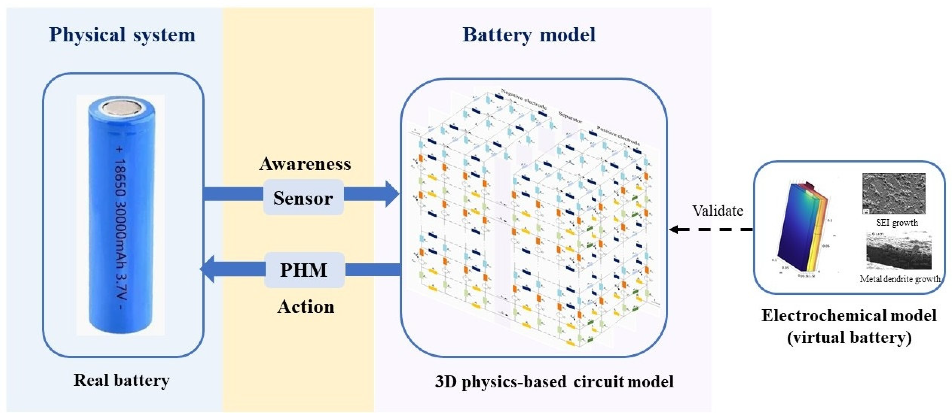
As shown in Figure 2, the 3D physics-based circuit model serves as the computationally efficient core for real-time battery simulation. The evaluation of the proposed model focuses on terminal-voltage behavior under degradation-associated scenarios.
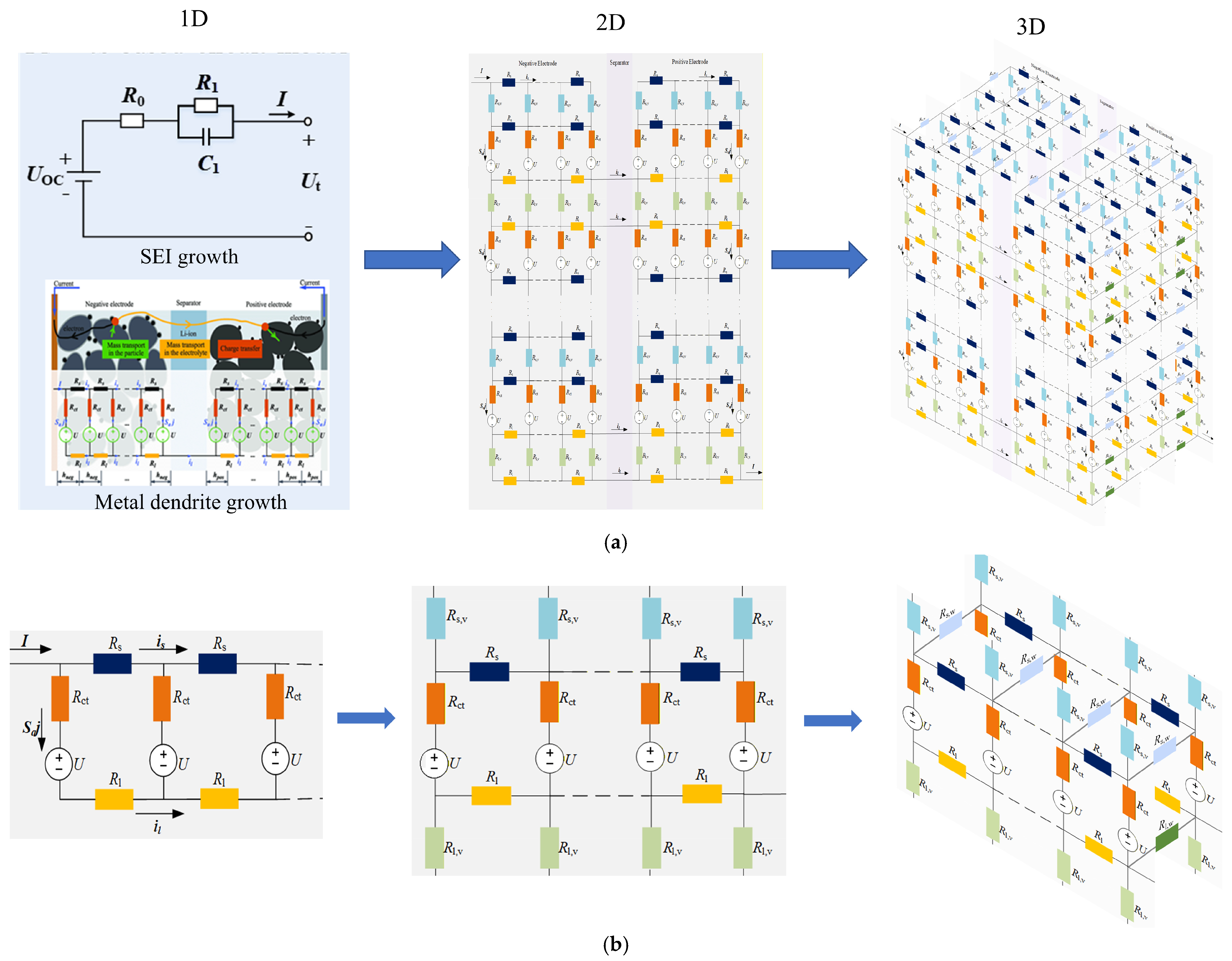
As shown in Figure 3a, the physics-based circuit-modeling pathway was developed progressively toward the 3D model used as the online core of the proposed framework. Previous work developed the physics-based 1RC ECM for SEI growth, including temperature-dependent behaviors [9,10], and subsequently extended the approach to a transmission line circuit model that represents distributed solid-phase conduction, electrolyte transport, and interfacial reactions associated with SEI growth and metal dendrite growth [11]. These developments motivate the 3D circuit representation.
Although the 1RC ECM provides a computationally efficient representation of bulk battery behavior, its lumped structure assumes uniform internal states and cannot resolve spatial gradients in potential, current density, or degradation along the electrode thickness. However, in porous electrodes, significant through-thickness variations exist in solid-phase and electrolyte-phase potentials, lithium concentration, and reaction rates, particularly under high-rate operation or ageing conditions. These gradients are essential to capture the local driving forces for side reactions such as SEI growth and metal dendrite growth, which depend on spatially distributed overpotentials and transport limitations.
To incorporate these through-thickness gradients while retaining the circuit-based modeling philosophy, the 1D transmission line model [11] represents the porous electrode as a series of interconnected circuit units distributed along the spatial domain. Each unit consists of an open-circuit voltage source (U), a solid-phase resistance (Rs), an electrolyte resistance (Rl), and a charge-transfer resistance (Rct). The open-circuit voltage is determined by the lithium concentration at the particle surface and can be expressed as follows:
U = U c s , s u r f .
The electronic conduction process in the solid phase is represented by the resistance Rs. According to Ohm’s law, the solid-phase current density i s satisfies the following:
i s = − σ s e f f ∇ ϕ s .
By discretizing the electrode into finite spatial segments, the corresponding circuit resistance can be expressed as follows:
R s = − h ∇ ϕ s i s ,
where h is the length of the mesh elements.
Similarly, ion transport in the electrolyte phase is represented by the electrolyte resistance Rl. The electrolyte phase current density i l is governed by concentrated solution theory and depends on both potential gradients and concentration gradients. After spatial discretization, the equivalent electrolyte resistance is given by the following:
R l = − h ∇ ϕ e i l
The electrochemical reaction occurring at the electrode–electrolyte interface is represented by the charge-transfer resistance Rct. Under near-equilibrium conditions, the Butler–Volmer equation can be linearized, yielding the charge-transfer resistance, as follows:
R c t   =   R T F j S a h .
The 1D transmission line circuit topology thus improves upon the lumped 1RC ECM by resolving through-thickness gradients, which are essential for capturing the distribution of reaction rates and overpotentials across the electrode thickness. However, it still assumes spatial uniformity along the in-plane directions. In practical large-format batteries, factors such as non-uniform cooling, asymmetric tab placement, and localized current-density variations create significant in-plane heterogeneities in temperature, reaction rates, and degradation progression. These spatial non-uniformities are particularly critical for incipient fault mechanisms such as SEI growth and metal dendrite growth, both of which exhibit strong sensitivity to local overpotential and temperature distributions. Uneven development of these degradation modes can accelerate localized aging and increase the risk of internal short circuits, yet such in-plane variations cannot be captured by a 1D through-thickness representation alone. To address this limitation, the 1D transmission line circuit topology is extended into a 3D transmission line circuit model [12]. The negative electrode, separator, and positive electrode are each discretized using eight through-thickness elements and nine stored grid points. The domain-wise grid points are retained separately and coupled through the corresponding interface conditions, resulting in 27 stored nodes along the complete through-thickness direction. Eight nodes are used in each of the width and height directions. Interior nodes are coupled to their nearest neighbors in the three spatial directions, whereas boundary nodes are subject to the corresponding electrical and thermal boundary conditions.
The 27 × 8 × 8 spatial discretization was selected by considering both the numerical requirements of the adopted fourth-order scheme and the computational objective of the proposed online-oriented model. Following the through-thickness discretization strategy in [28], at least eight elements are required in each electrode or separator subdomain to implement the fourth-order spatial operator. The negative electrode, separator, and positive electrode were therefore each discretized using eight elements and nine stored grid points, resulting in 27 stored nodes along the complete through-thickness direction. Because the model in [28] is 1D and does not prescribe an in-plane resolution, eight nodes were used in each of the width and height directions in the present 3D extension, giving a total of 1728 electrochemical-thermal nodes. The adequacy of this discretization was evaluated by refining the grid to 39 × 10 × 10 and 51 × 12 × 12 under otherwise identical conditions. Relative to the 51 × 12 × 12 fine-grid solution, the 27 × 8 × 8 grid produced a terminal-voltage root mean square error (RMSE) of 7.99 mV and a maximum-temperature difference of 0.028 K. Refining only the in-plane resolution from 8 × 8 to 10 × 10 changed the voltage trajectory by an RMSE of only 0.169 mV, indicating that the baseline in-plane resolution was sufficient for the evaluated condition. In contrast, the 51 × 12 × 12 grid contained 4.25 times as many spatial nodes and required more than five times the wall-clock computation time. The 27 × 8 × 8 discretization was therefore selected as an accuracy–cost compromise for the intended online-oriented application.
As enlarged in Figure 3b, the construction starts from a 1D through-thickness circuit unit, in which the solid-phase and electrolyte-phase transport branches are represented by Rs and Rl, respectively, and each local electrochemical unit contains a voltage source U and a charge-transfer element Rct. The 2D topology is obtained by replicating the 1D unit along the first in-plane direction v and connecting adjacent units through the transverse solid-phase and electrolyte-phase resistances Rs,v and Rl,v. The 3D network is then formed by stacking the 2D circuit sheets along the second in-plane direction and introducing the corresponding inter-sheet couplings Rs,w and Rl,w. Therefore, each node retains the local U–Rct electrochemical branch while being electrically coupled to neighboring nodes in the through-thickness and two in-plane directions. A bidirectionally coupled thermal network uses the same spatial connectivity to update temperature-dependent transport and kinetic parameters.

4. Evaluation and Discussion

4.1. Virtual-Battery-Aided Cross-Model Evaluation

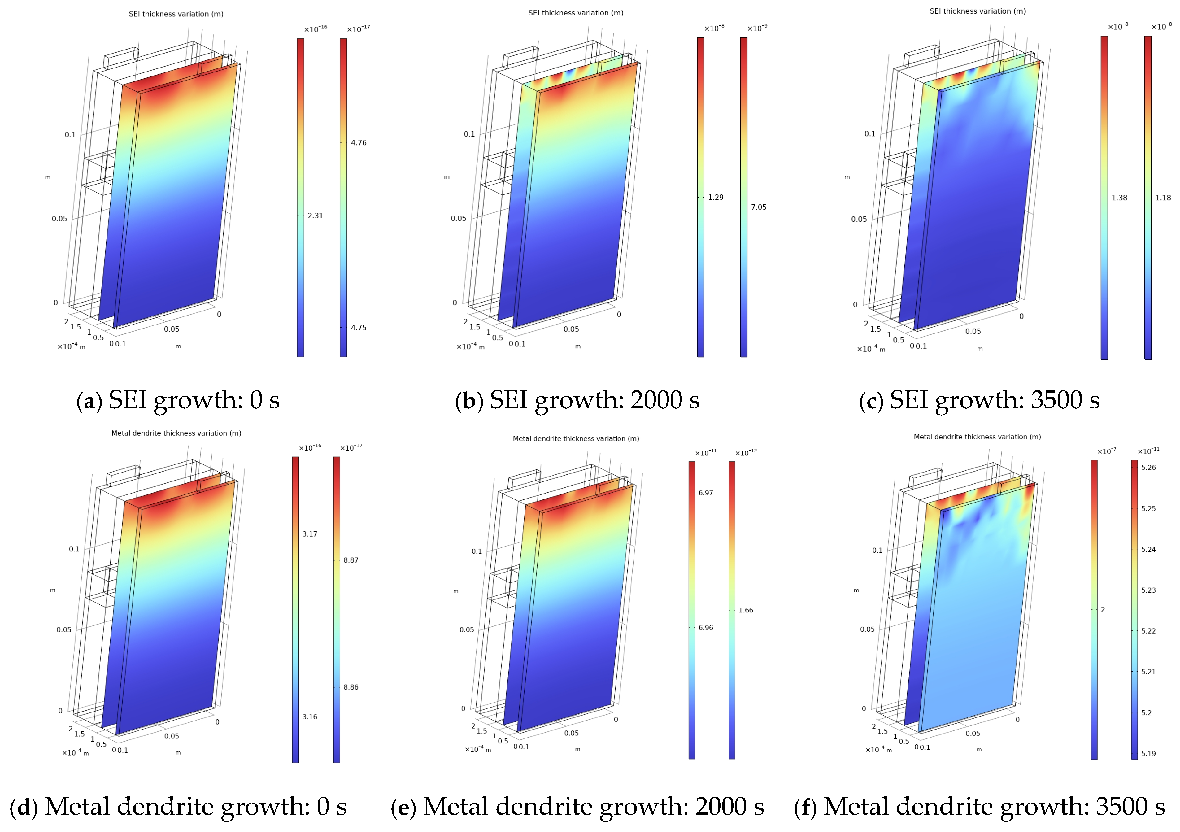
As described in Section 3.2, the 3D electrochemical virtual battery developed [8] is used as an offline numerical reference. It integrates established governing formulations from the battery-modeling literature rather than introducing new fundamental electrochemical laws. Its electrochemical core follows the Doyle–Fuller–Newman framework [18], its spatial electrochemical-thermal coupling is formulated with reference to validated multidimensional battery models [35,36,37,38], and established side-reaction formulations represent SEI growth and metal dendrite growth. The virtual battery resolves coupled charge and mass transport, interfacial kinetics, heat generation and transfer, SEI growth, and metallic lithium deposition throughout the cell domain. These outputs provide reference trajectories and internal states for evaluating and interpreting the circuit-modeling framework. The virtual battery provides time- and space-resolved mechanism-oriented states. Figure 4 presents representative distributions of SEI thickness and equivalent metal-dendrite-growth thickness at the beginning, an intermediate time, and the end of the simulated charging process. Both states increase and develop spatially non-uniform distributions, with larger values concentrated near the upper electrode and tab region.
Take SEI growth as an example. Terminal-voltage trajectories generated by the virtual battery are retained as high-fidelity numerical reference profiles. The corresponding physics-based circuit model outputs are treated as predictions to be evaluated against those references at the 20th, 30th, 40th, 50th, and 60th ageing cycles.
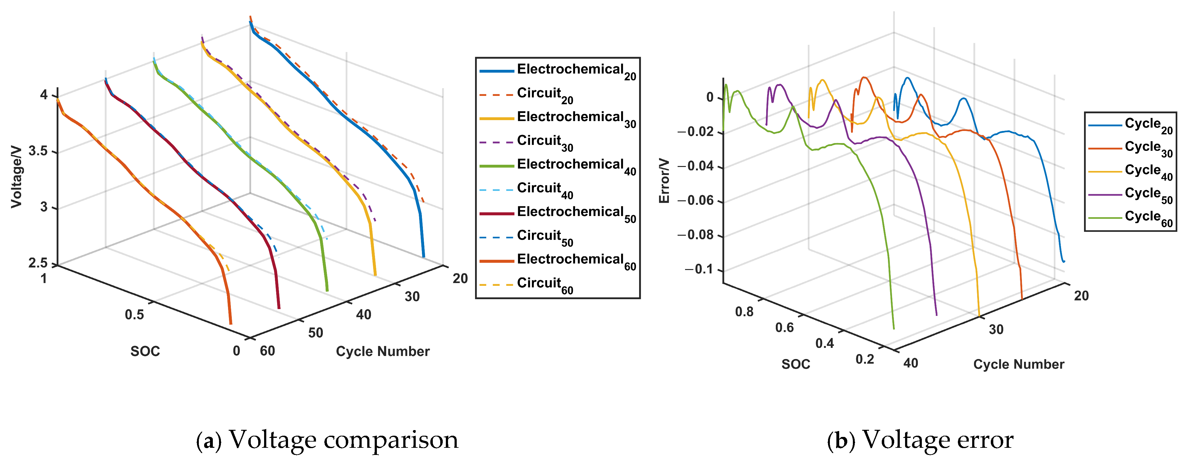
As shown in Figure 5, the 1RC ECM reproduces the principal terminal-voltage evolution generated by the virtual battery reference across the evaluated ageing conditions. All evaluated discharge cases remain within a common root mean relative error (MRE) bound of 1%. The main deviations occur in the low-SOC region, where the lumped 1RC topology cannot fully reproduce the nonlinear electrochemical polarization and electrolyte-transport behavior represented by the virtual battery. Early-cycle differences are also sensitive to initialization and fast electrochemical dynamics that are not explicitly represented by the 1RC ECM.
The 3D transmission line circuit model is parameterized using the virtual battery’s spatially distributed information—including local overpotentials, temperature, current densities, and degradation states—at each spatial node of the 3D topology. These distributed quantities are embedded directly into the circuit elements at each node, ensuring that the model’s internal state evolution is consistent with the virtual battery’s physics-based predictions. The terminal-voltage comparison for the 3D model therefore serves as a critical aggregate validation: since voltage is the external manifestation of all internal electrochemical, thermal, and degradation processes, accurate voltage matching confirms that the embedded distributed behavior is correctly represented at the system level.
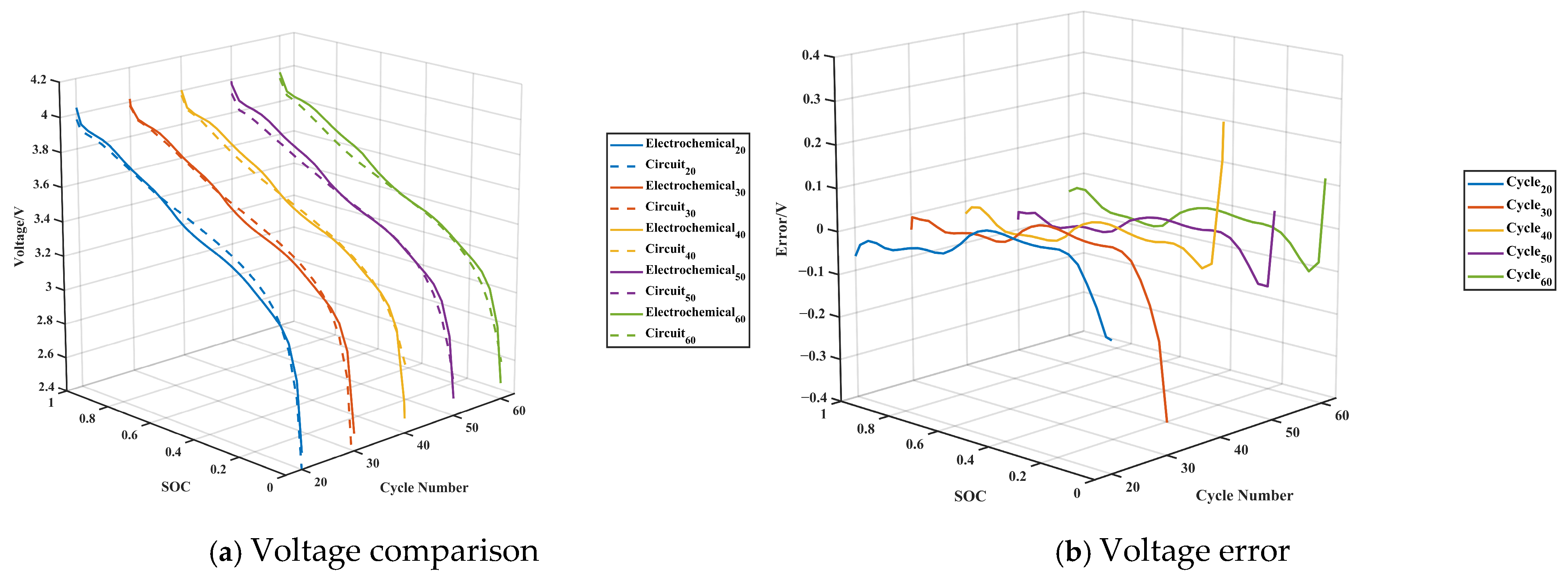
Figure 6 presents the evaluation results for the 3D transmission line circuit model under the same ageing cycle conditions. Compared with the 1RC ECM, the 3D circuit model achieves improved agreement with the virtual battery reference, particularly in the low-SOC region, where its spatially distributed representation better captures the local polarization and transport limitations that underlie terminal-voltage behavior. The MRE remains consistently below 1.3% bound across the evaluated cases, confirming that the increased spatial resolution of the 3D topology preserves the fidelity of the lumped pathway while enabling richer internal-state information. These results motivate the established three-dimensional circuit model as the framework’s higher-spatial-resolution online modeling core, transitioning from the lumped baseline toward a spatially resolved representation suitable for microgrid situation awareness.
At Cycle 20, the early-transient error dominates due to initialization sensitivity, whereas the low-SOC nonlinearity is moderate because the stoichiometry window remains wide. By Cycle 40, SEI growth increases the film resistance, amplifying the low-SOC polarization error while the early-transient error diminishes after the first few seconds. At Cycle 60, the loss of cyclable lithium shifts the knee point earlier in discharge, making the low-SOC deviation appear sooner and contribute over a broader voltage range. For the 1RC ECM, larger deviations occur during early-cycle transients and at low SOC. The early-cycle deviations stem from sensitivity to initialization parameters and the inability of the lumped topology to capture fast initial transients, whereas the low-SOC deviations arise from strong nonlinear polarization and electrolyte transport limitations near the discharge end. The 3D transmission line circuit model substantially reduces the early-cycle errors by embedding spatially distributed states at each node, yet residual low-SOC discrepancies persist due to the inherent simplification of concentrated solution transport in the circuit representation.
A comparative computational assessment among the considered modeling approaches is summarized in Table 1. As the physics-based modeling framework evolves from the lumped 1RC ECM toward the 3D transmission line circuit model, computational cost increases progressively to accommodate higher spatial resolution and richer electrochemical–thermal information. The 1RC ECM achieves the lowest per-step computation time (0.407 ms), serving as a computationally lightweight baseline. The 3D transmission line circuit model, which inherits the circuit-based formulation while extending it to 3D spatial discretization, exhibits a mean solver time of 0.16 s per step—still approximately one order of magnitude faster than the virtual battery (1.79 s per step). This progressive computational scaling, together with the voltage fidelity demonstrated in Figure 5 and Figure 6, supports the feasibility of deploying the 3D physics-based circuit model as an online modeling core within microgrid energy management systems, where both timeliness and interpretability are essential.

4.2. Statistical Analyses of the Proposed 3D Physics-Based Circuit Model

To complement the trajectory-based comparisons in Section 4.1, statistical analyses were conducted for the 3D transmission line circuit model at Cycles 20, 30, 40, 50, and 60.
Model agreement was evaluated using the Pearson correlation coefficient (r), Nash–Sutcliffe efficiency (NSE), residual standard deviation (SD), mean absolute error (MAE), RMSE, and MRE. As shown in Table 2, the statistics were calculated separately for each ageing cycle and for the pooled multicycle dataset.
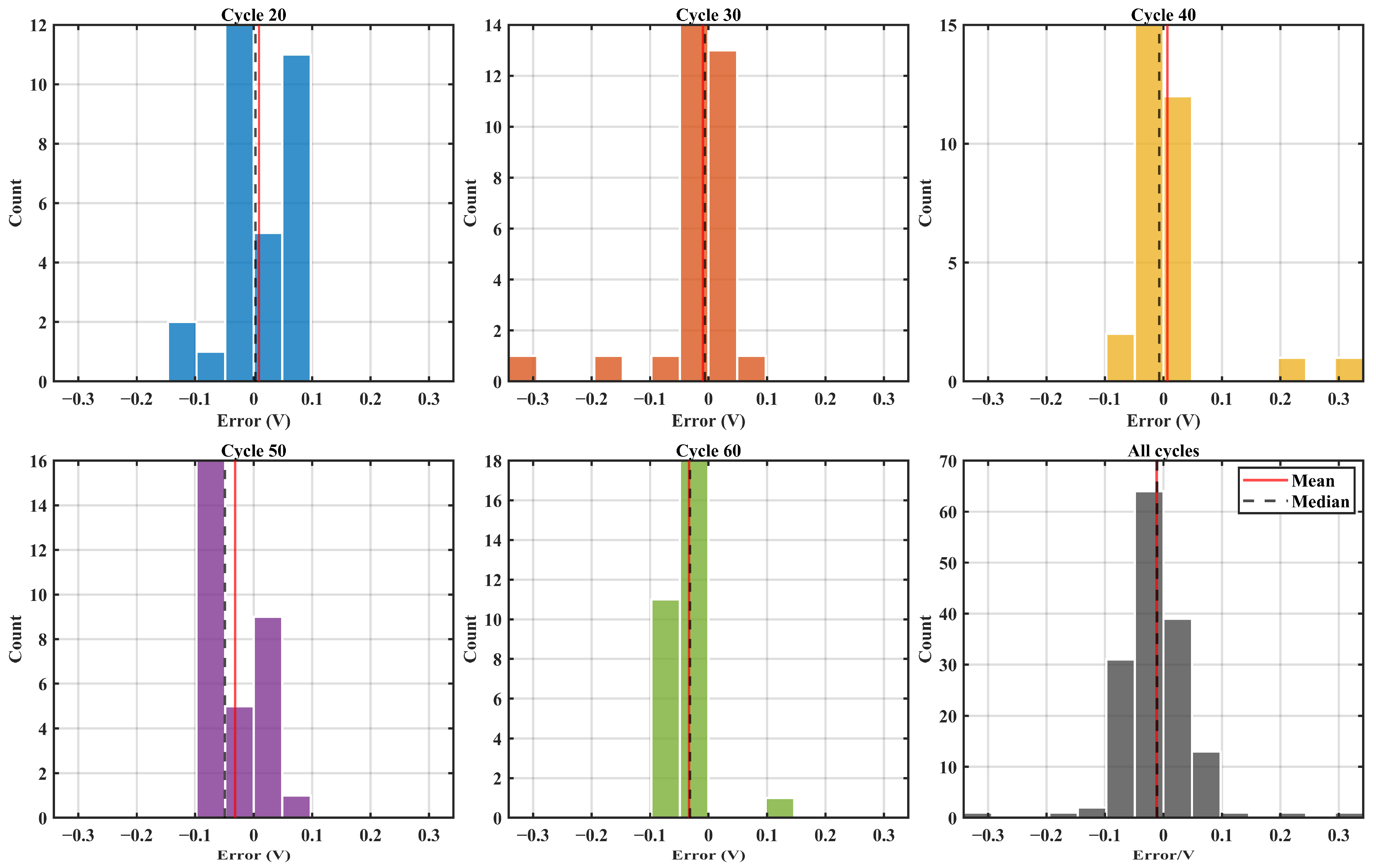
The error distributions are shown in Figure 7. The solid red and dashed black lines indicate the mean and median residuals, respectively. Cycles 30 and 40 exhibited the largest residual dispersions, with SD values of 71.39 and 75.19 mV and RMSE values of 70.86 and 74.26 mV, respectively. Inspection of the pointwise results shows that these values are dominated by a small number of discharge-end samples at SOC <= 0.1, particularly at the final SOC = 0 points, rather than by a broad low-SOC mismatch over the complete trajectory.
A more appropriate explanation for these isolated endpoint residuals is the high voltage sensitivity around the discharge knee. In this region, the magnitude of d V d S O C increases sharply, so a small difference in SOC, time alignment, or cutoff-point location can produce a comparatively large voltage residual even when the preceding 3D circuit model trajectory agrees well with the reference. SEI growth consumes cyclable lithium and increases the interfacial film resistance, which can shift the knee location and modify its local slope. These degradation effects may therefore amplify endpoint sensitivity as the cycles progress. The residual SD decreased to 39.25 and 41.38 mV at Cycles 50 and 60, respectively, despite the continued increase in SEI thickness. Across all cycles, the MAE remained within 39.47–43.82 mV and the MRE ranged from 1.14% to 1.30%, confirming that the overall error did not increase monotonically with cycle number.
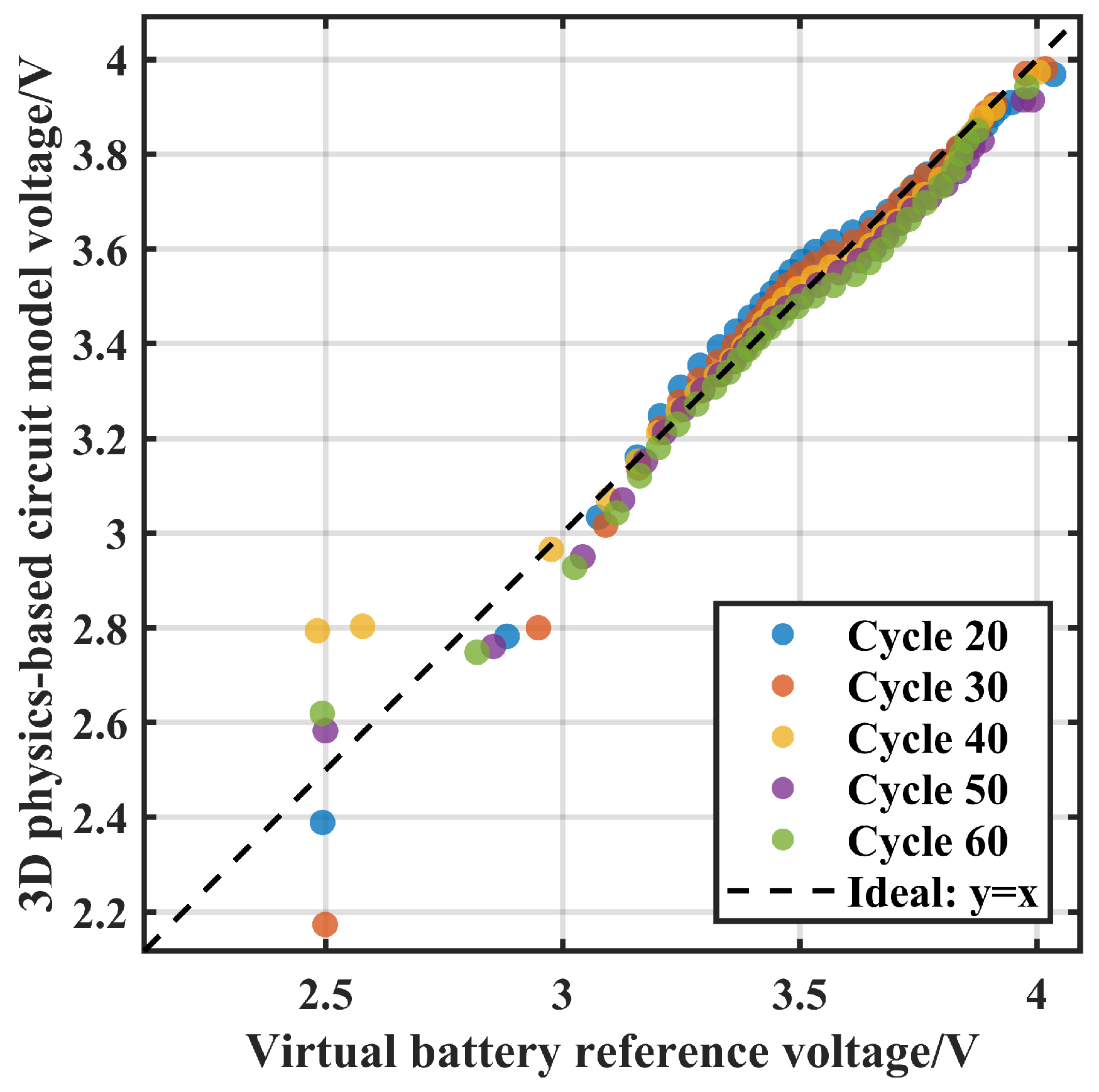
Figure 8 summarizes the overall voltage agreement between the 3D transmission line circuit model and the virtual battery reference across different SEI growth stages. The dashed line represents the ideal agreement. Most data points remain close to the identity line, with a pooled Pearson coefficient of 0.9844 and an NSE of 0.9678. This result indicates that the model preserves the principal voltage evolution as SEI growth progresses. The limited deviations at the lowest reference voltages correspond mainly to isolated discharge-end samples and do not represent a systematic mismatch over the broader low-SOC region. Although the overall voltage correlation remains consistently high across the evaluated cycles, the cycle-specific residual distributions exhibit more noticeable variations in dispersion and bias.
The high agreement with the virtual battery and the computational efficiency indicates that the proposed model is suitable as an online-oriented battery information layer. Rather than replacing conventional measurements, it augments terminal measurements with model-informed internal-state estimation, providing degradation-related information that can support future microgrid situation awareness.

5. Conclusions

This paper develops a 3D physics-based circuit modeling framework for battery incipient fault in microgrid situation awareness, focusing on SEI growth and metal dendrite growth. The established 3D transmission line circuit modeling capability is the framework’s real-time core. A high-fidelity electrochemical virtual battery was used offline to generate mechanism-consistent reference trajectories and internal degradation states for cross-model evaluation and interpretation. Across the evaluated discharge cases, the circuit model pathway shows voltage MREs below 1.3% relative to the virtual battery reference and demonstrates the computational efficiency for real-time applications. The proposed framework provides an online-oriented battery-information layer capable of enriching conventional terminal measurements with model-informed degradation indicators for future microgrid situation awareness applications. Future work will combine other fault-sensitive measurements, implement quantitative fault classification, and evaluate the indicators within microgrid energy management and islanding studies.

Author Contributions

Conceptualization, M.-Y.C., Z.W. and J.S.; methodology, Z.W.; software, Z.W. and J.S.; validation, Z.W. and J.S.; formal analysis, Z.W.; investigation, Z.W.; data curation, Z.W. and J.S.; writing—original draft preparation, Z.W. and J.S.; writing—review and editing, Z.W., J.S. and M.-Y.C.; visualization, Z.W.; supervision, M.-Y.C.; project administration, M.-Y.C.; funding acquisition, M.-Y.C. All authors have read and agreed to the published version of the manuscript.

Funding

This research was funded by the National Natural Science Foundation of China (NSFC), grant number 6251101236.

Institutional Review Board Statement

Not applicable.

Informed Consent Statement

Not applicable.

Data Availability Statement

The data supporting the findings of this study are available upon reasonable request.

Conflicts of Interest

The authors declare no conflicts of interest.

References

  1. Cheng, Z.; Duan, J.; Chow, M.Y. To centralize or to distribute: That is the question: A comparison of advanced microgrid management systems. IEEE Ind. Electron. Mag. 2018, 12, 6–24. [Google Scholar] [CrossRef] [Scilit]
  2. Wu, B.; Widanage, W.D.; Yang, S.; Liu, X. Battery digital twins: Perspectives on the fusion of models, data and artificial intelligence for smart battery management systems. Energy AI 2020, 1, 100016. [Google Scholar] [CrossRef] [Scilit]
  3. Wu, Y.; Wang, W.; Ming, J.; Li, M.; Xie, L.; He, X.; Wang, J.; Liang, S.; Wu, Y. An exploration of new energy storage system: High energy density, high safety, and fast charging lithium ion battery. Adv. Funct. Mater. 2019, 29, 1805978. [Google Scholar]
  4. An, S.J.; Li, J.; Daniel, C.; Mohanty, D.; Nagpure, S.; Wood, D.L. The state of understanding of the lithium-ion-battery graphite solid electrolyte interphase (SEI) and its relationship to formation cycling. Carbon 2016, 105, 52–76. [Google Scholar] [CrossRef] [Scilit]
  5. Zhang, X.; Wang, A.; Liu, X.; Luo, J. Dendrites in lithium metal anodes: Suppression, regulation, and elimination. Acc. Chem. Res. 2019, 52, 3223–3232. [Google Scholar] [CrossRef] [Scilit] [PubMed]
  6. Feng, X.; Ouyang, M.; Liu, X.; Lu, L.; Xia, Y.; He, X. Thermal runaway mechanism of lithium ion battery for electric vehicles: A review. Energy Storage Mater. 2018, 10, 246–267. [Google Scholar] [CrossRef] [Scilit]
  7. Liu, H.; Zhang, L.; Li, L. Progress on the fault diagnosis approach for lithium-ion battery systems: Advances, challenges, and prospects. Prot. Control Mod. Power Syst. 2024, 9, 16–41. [Google Scholar] [CrossRef] [Scilit]
  8. Shao, J.; Chow, M.Y.; Tan, Z.; Jin, H. Solid Electrolyte Interface Growth Fault Modeling for Battery State of Health Simulation. In Proceedings of the 2025 IEEE International Conference on Industrial Technology (ICIT), Wuhan, China, 26–28 March 2025; pp. 1–6. [Google Scholar]
  9. Wang, Z.; Chow, M.Y.; Tan, Z.; Jin, H. Modelling of the Solid Electrolyte Interface Growth Using Physics-Based Equivalent Circuit Model. In Proceedings of the 2025 IEEE International Conference on Industrial Technology (ICIT), Wuhan, China, 26–28 March 2025; pp. 1–6. [Google Scholar]
  10. Wang, Z.; Chow, M.Y. Temperature-Dependent Modeling of the Solid Electrolyte Interface Growth via a Physics-Based Equivalent Circuit Framework. In Proceedings of the 2026 IEEE International Conference on Industrial Technology (ICIT), Monterrey, Mexico, 4–6 March 2026; pp. 1–6. [Google Scholar]
  11. Wang, Z.; Chow, M.Y. Battery Modeling of SEI and Metal Dendrite Growth: A Transmission Line Circuit Framework with Genetic Algorithm-Identified Parameters. In Proceedings of the 2025 IEEE 20th Conference on Industrial Electronics and Applications (ICIEA), Yantai, China, 3–6 August 2025; pp. 1–6. [Google Scholar]
  12. Wang, Z.; Chow, M.Y. Enhancing Situation Awareness in Microgrids: A 3D Transmission Line Circuit Modeling Approach for Batteries. IEEE, 2026; accepted. [CrossRef] [Scilit]
  13. Munir, A.; Aved, A.; Blasch, E. Situational awareness: Techniques, challenges, and prospects. AI 2022, 3, 55–77. [Google Scholar] [CrossRef] [Scilit]
  14. Adasah, S.N.; Wang, Z.; Hu, S.; Capezza, S.; Shao, J.; Chow, M.-Y. Review of Fault Diagnosis Based Protection Mechanisms for Battery Energy Storage Systems. In Proceedings of the 2024 IEEE 33rd International Symposium on Industrial Electronics (ISIE), Ulsan, Republic of Korea, 18–21 June 2024; pp. 1–6. [Google Scholar]
  15. Ardeshiri, R.R.; Balagopal, B.; Alsabbagh, A.; Ma, C.; Chow, M.-Y. Machine Learning Approaches in Battery Management Systems: State of the Art: Remaining Useful Life and Fault Detection. In Proceedings of the 2020 2nd IEEE International Conference on Industrial Electronics for Sustainable Energy Systems (IESES), Cagliari, Italy, 1–3 September 2020; pp. 61–66. [Google Scholar]
  16. Tran, M.K.; Mevawalla, A.; Aziz, A.; Panchal, S.; Xie, Y.; Fowler, M. A review of lithium-ion battery thermal runaway modeling and diagnosis approaches. Processes 2022, 10, 1192. [Google Scholar] [CrossRef] [Scilit]
  17. Edge, J.S.; O’Kane, S.; Prosser, R.; Kirkaldy, N.D.; Patel, A.N.; Hales, A.; Ghosh, A.; Ai, W.; Chen, J.; Yang, J.; et al. Lithium ion battery degradation: What you need to know. Phys. Chem. Chem. Phys. 2021, 23, 8200–8221. [Google Scholar] [CrossRef] [Scilit] [PubMed]
  18. Doyle, M.; Fuller, T.F.; Newman, J. Modeling of galvanostatic charge and discharge of the lithium/polymer/insertion cell. J. Electrochem. Soc. 1993, 140, 1526–1533. [Google Scholar] [CrossRef] [Scilit]
  19. Lawder, M.T.; Northrop, P.W.C.; Subramanian, V.R. Model-based SEI layer growth and capacity fade analysis for EV and PHEV batteries and drive cycles. J. Electrochem. Soc. 2014, 161, A2099. [Google Scholar] [CrossRef] [Scilit]
  20. Deshpande, R.D.; Bernardi, D.M. Modeling solid-electrolyte interphase (SEI) fracture: Coupled mechanical/chemical degradation of the lithium ion battery. J. Electrochem. Soc. 2017, 164, A461. [Google Scholar] [CrossRef] [Scilit]
  21. Rahimian, S.K.; Forouzan, M.M.; Han, S.; Tang, Y. A generalized physics-based calendar life model for Li-ion cells. Electrochim. Acta 2020, 348, 136343. [Google Scholar] [CrossRef] [Scilit]
  22. Ge, H.; Aoki, T.; Ikeda, N.; Suga, S.; Isobe, T.; Li, Z.; Tabuchi, Y.; Zhang, J. Investigating lithium plating in lithium-ion batteries at low temperatures using electrochemical model with NMR assisted parameterization. J. Electrochem. Soc. 2017, 164, 1050–1060. [Google Scholar] [CrossRef] [Scilit]
  23. Yang, X.G.; Leng, Y.; Zhang, G.; Ge, S.; Wang, C.-Y. Modeling of lithium plating induced aging of lithium-ion batteries: Transition from linear to nonlinear aging. J. Power Sources 2017, 360, 28–40. [Google Scholar] [CrossRef] [Scilit]
  24. Balagopal, B.; Huang, C.S.; Chow, M.Y. Effect of Calendar Ageing on SEI Growth and Its Impact on Electrical Circuit Model Parameters in Lithium-ion Batteries. In Proceedings of the 2018 IEEE International Conference on Industrial Electronics for Sustainable Energy Systems (IESES), Hamilton, New Zealand, 31 January–2 February 2018; pp. 32–37. [Google Scholar]
  25. Balagopal, B.; Huang, C.S.; Chow, M.Y. Effect of Calendar Aging on Li Ion Battery Degradation and SOH. In Proceedings of the IECON 2017-43rd Annual Conference of the IEEE Industrial Electronics Society, Beijing, China, 29 October–1 November 2017; pp. 7647–7652. [Google Scholar]
  26. Huang, C.S.; Chow, M.Y. Robust state-of-charge estimation for lithium-ion batteries over full SOC range. IEEE J. Emerg. Sel. Top. Ind. Electron. 2021, 2, 305–313. [Google Scholar] [CrossRef] [Scilit]
  27. Rahimi-Eichi, H.; Ojha, U.; Baronti, F.; Chow, M.-Y. Battery management system: An overview of its application in the smart grid and electric vehicles. IEEE Ind. Electron. Mag. 2013, 7, 4–16. [Google Scholar] [CrossRef] [Scilit]
  28. Geng, Z.; Wang, S.; Lacey, M.J.; Brandell, D.; Thiringer, T. Bridging physics-based and equivalent circuit models for lithium-ion batteries. Electrochim. Acta 2021, 372, 137829. [Google Scholar] [CrossRef] [Scilit]
  29. Cai, C.; Gong, Y.; Fotouhi, A.; Auger, D.J. A novel hybrid electrochemical equivalent circuit model for online battery management systems. J. Energy Storage 2024, 99, 113142. [Google Scholar] [CrossRef] [Scilit]
  30. Li, Y.; Qi, H.; Shi, X.; Jian, Q.; Lan, F.; Chen, J. A Physics-Based Equivalent Circuit Model and State of Charge Estimation for Lithium-Ion Batteries. Energies 2024, 17, 3782. [Google Scholar] [CrossRef] [Scilit]
  31. Yang, B.; Wang, D.; Zhang, B.; Chen, S.; Sun, X.; Wang, T. Aging diagnosis-oriented three-scale impedance model of lithium-ion battery inspired by and reflecting morphological evolution. J. Energy Storage 2023, 59, 106357. [Google Scholar] [CrossRef] [Scilit]
  32. Lee, P.Y.; Nagar, A.; Yoo, K.; Kim, J. Impedance-based health indicators determination for degradation diagnosis and fault identification of lithium-ion batteries under extreme operating conditions. J. Electroanal. Chem. 2023, 942, 117572. [Google Scholar] [CrossRef] [Scilit]
  33. Fan, C.; Zhang, K.; Peng, Q.; Tian, J.; Liu, K.; Chung, C.Y. Fast characterization of lithium-ion battery impedance and nonlinearity using optimized multisine perturbation signal. IEEE Trans. Ind. Electron. 2025, 72, 11395–11405. [Google Scholar] [CrossRef] [Scilit]
  34. Zhang, Y.; Zhang, P.; Hu, J.; Zhang, C.; Zhang, L.; Wang, Y.; Zhang, W. Fault diagnosis method of lithium-ion battery leakage based on electrochemical impedance spectroscopy. IEEE Trans. Ind. Appl. 2023, 60, 1879–1889. [Google Scholar] [CrossRef] [Scilit]
  35. Dickinson, E.J.F.; Wain, A.J. The Butler-Volmer equation in electrochemical theory: Origins, value, and practical application. J. Electroanal. Chem. 2020, 872, 114145. [Google Scholar] [CrossRef] [Scilit]
  36. Lin, X.W.; Zhou, Z.F.; Zhu, X.G.; Chen, B.; Zhu, H.; Ben, N.-Y.; Wang, X.-D.; Xu, W.-W. Non-uniform thermal characteristics investigation of three-dimensional electrochemical-thermal coupled model for pouch lithium-ion battery. J. Clean. Prod. 2023, 417, 13791. [Google Scholar] [CrossRef] [Scilit]
  37. Huang, Y.; Lai, X.; Ren, D.; Kong, X.; Han, X.; Lu, L.; Zheng, Y. Thermal and stoichiometry inhomogeneity investigation of large-format lithium-ion batteries via a three-dimensional electrochemical-thermal coupling model. Electrochim. Acta 2023, 468, 143212. [Google Scholar] [CrossRef] [Scilit]
  38. Zhao, R.; Liu, J.; Gu, J. The effects of electrode thickness on the electrochemical and thermal characteristics of lithium ion battery. Appl. Energy 2015, 139, 220–229. [Google Scholar] [CrossRef] [Scilit]
Figure 1. The importance of battery situation awareness in microgrids.
Batteries 12 00283 g001
Figure 2. Workflow of the 3D physics-based circuit model.
Batteries 12 00283 g002
Figure 3. Evolution summary of the physics-based circuit modeling pathway. (a) Evolution from the 1D circuit model, including the SEI growth and metal dendrite growth submodels, to the 2D network and the complete 3D circuit model. (b) Enlarged view of a representative section of the 3D circuit model, showing the detailed component arrangement and electrical connections.
Batteries 12 00283 g003
Figure 4. Spatial evolution of SEI thickness and metal dendrite growth thickness.
Batteries 12 00283 g004
Figure 5. Cross-model evaluation between the 1RC ECM and the virtual battery.
Batteries 12 00283 g005
Figure 6. Cross-model evaluation between the 3D transmission line circuit model and the virtual battery.
Batteries 12 00283 g006
Figure 7. Error distributions of the 3D circuit model voltage relative to the virtual battery reference.
Batteries 12 00283 g007
Figure 8. Correlation between the voltages predicted by the 3D transmission line circuit model and the virtual battery reference at different ageing cycles.
Batteries 12 00283 g008
Table 1. Computational comparison between the circuit models and the virtual battery.
1RC ECM3D Transmission Line Circuit ModelVirtual Battery
Mean solver time per step0.407 ms0.16 s1.79 s
Indicative computational suitabilityHighHighLow
Table 2. Statistical validation of the multicycle 3D transmission line circuit model.
CycleLSEI (nm)Pearson rNSESD (mV)MAE (mV)RMSE (mV)MRE (%)
20185.390.98880.976651.4743.8251.461.30
30236.580.98610.954171.3939.6270.861.28
40279.970.98860.956975.1939.7674.261.30
50318.510.99450.977739.2539.4749.921.14
60353.400.99320.974641.3841.6652.531.24
All cycles-0.98440.967859.8640.8660.771.25
Disclaimer/Publisher’s Note: The statements, opinions and data contained in all publications are solely those of the individual author(s) and contributor(s) and not of MDPI and/or the editor(s). MDPI and/or the editor(s) disclaim responsibility for any injury to people or property resulting from any ideas, methods, instructions or products referred to in the content.