3.1. Characterization of TTA-GPEs
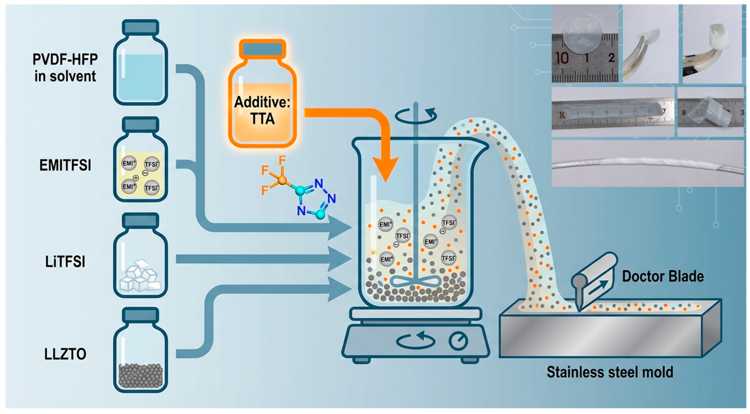
The GPEs and the TTA-GPEs were fabricated via a facile solution casting method (
Figure 1). Macroscopically, the resulting membranes exhibit a uniform, smooth, and translucent white morphology. Notably, the film thickness is precisely engineered to approximately 25 μm (
Figure S1). This ultrathin profile offers two critical advantages: first, it significantly minimizes the mass and volume of inactive components, thereby maximizing the gravimetric energy density of the full cell; second, it substantially shortens the lithium-ion transport pathways, establishing a physical foundation for reducing overall internal resistance. Despite this minimal thickness, the electrolyte membranes demonstrate exceptional mechanical flexibility and robust self-supporting strength. As evidenced by flexibility tests, the films can be curled into tight spiral structures or wound around thin glass rods without undergoing brittle fracture or delamination. This combination of ultrathin geometry and high mechanical integrity is pivotal, as it not only meets the rigorous winding requirements for pouch cell assembly but also effectively buffers electrode volume expansion during cycling. Consequently, this capability is essential for maintaining intimate physical contact at the electrode/electrolyte interface, which is a prerequisite for ensuring superior long-term cycling stability.
The regulatory mechanism of the TTA additive on the microstructural evolution of the gel polymer electrolyte is elucidated via scanning electron microscopy (SEM) and energy-dispersive X-ray spectroscopy (EDS). As illustrated in
Figure S2, GPEs exhibit a rough and porous surface morphology, characterized by distinct pits and phase separation in localized regions. This microstructural heterogeneity is primarily attributed to the substantial surface energy mismatch between the inorganic LLZTO filler particles and the organic PVDF-HFP matrix. Such incompatibility induces severe agglomeration of LLZTO during film formation, consequently generating interfacial voids that are detrimental to continuous ion transport.
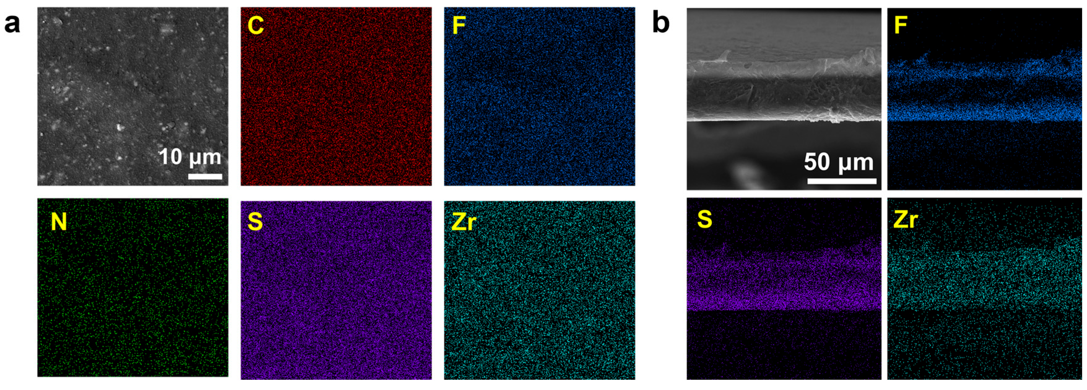
In stark contrast, upon introducing TTA as an interfacial modifier, the surface morphology of TTA-GPEs undergoes significant reconstruction, displaying a much smoother, denser, and defect-free texture where the original porous defects are virtually eliminated (
Figure 2a). This transformation indicates that the TTA molecule functions as a “molecular bridge” acting through its electron-rich functional groups to effectively enhance the interfacial compatibility between the inorganic and organic phases. Consequently, TTA promotes the uniform dispersion of LLZTO particles within the polymer matrix and suppresses phase separation behavior. Furthermore, EDS elemental mapping reveals a highly uniform dispersion of key elements—including C, F, N, S, and Zr—across the modified electrolyte surface. Specifically, the Zr element (representing LLZTO fillers) and the N, S, and F elements (originating from lithium salts and ionic liquids) show no evidence of localized aggregation or depletion. This confirms that LiTFSI, EMITFSI, LLZTO, and TTA have formed a homogeneous, molecular-level blended network within the PVDF-HFP host. Such a dense and chemically uniform surface structure is critical: it not only lowers the interfacial contact resistance between the electrolyte and the lithium metal anode, ensuring uniform ion flux during storage, but also effectively eliminates localized current density concentration caused by microscopic defects. Thus, this optimized microstructure provides a robust foundation for achieving highly uniform lithium deposition/stripping and superior long-term cycling stability.
Figure S2 and
Figure 2b illustrate the cross-sectional micro-morphology and corresponding elemental distributions of the GPEs and TTA-GPEs. As evidenced by the SEM images, both electrolytes maintain a high degree of macroscopic structural consistency, exhibiting a dense, continuous, and pore-free gel morphology. Notably, no phase separation or micro-crack defects induced by the incorporation of the small-molecule organic additive were detected. The membranes retain a uniform thickness of approximately 25 μm, with flat and parallel upper and lower surfaces, providing intuitive confirmation of the exceptional physicochemical compatibility between the TTA molecules and the polymer matrix, lithium salts, and ceramic fillers. Further EDS elemental mapping reveals that the key constituent elements—specifically F and S (representing the polymer backbone and lithium salts) and Zr (representing the inorganic fillers)—exhibit a continuous and highly homogeneous dispersion across the entire cross-section of the TTA-GPEs, with no localized agglomeration observed. This molecular-level uniformity suggests that TTA has not only successfully integrated into the gel network but also facilitated the stable dispersion of inorganic fillers, likely via interactions with its polar functional groups. Consequently, a compositionally homogeneous and structurally continuous bulk ion-transport channel is constructed, providing a robust microstructural guarantee for efficient ionic conduction and uniform lithium deposition.
3.2. Characterization of Properties of TTA-GPEs
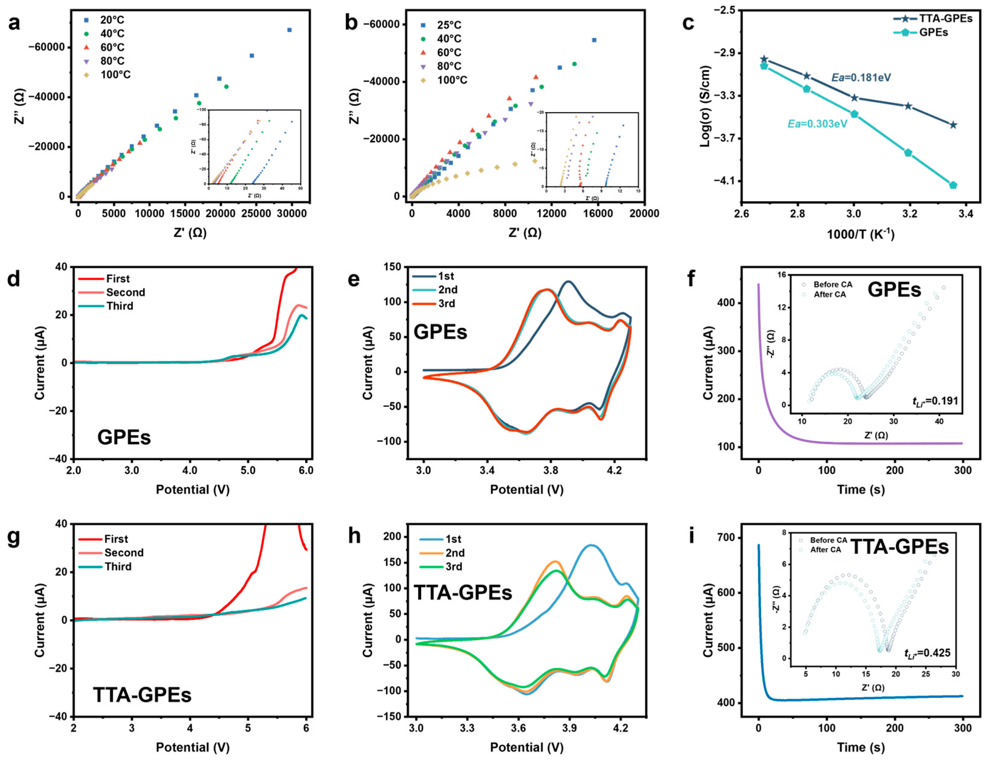
Ionic conductivity is a pivotal parameter determining the electrochemical performance of electrolytes; therefore, the temperature-dependent conductivity behaviors of GPEs and TTA-GPEs were systematically investigated. As illustrated in the variable-temperature electrochemical impedance spectroscopy (EIS) profiles (
Figure 3a,b), the pristine GPE exhibits a relatively modest room-temperature ionic conductivity of 0.073 mS cm
−1. In sharp contrast, the incorporation of TTA elevates this value significantly to 0.267 mS cm
−1. The Arrhenius plots derived from these measurements (
Figure 3c) further elucidate the profound impact of TTA on the ion transport kinetics within the gel polymer matrix. The TTA-GPEs demonstrate superior ionic conductivity across the entire tested temperature range compared to the baseline. Notably, the activation energy (
Ea) for lithium-ion migration exhibits a substantial decrease, dropping from 0.303 eV in the GPE to 0.181 eV in the TTA-GPE. This approximately 40% reduction quantitatively confirms that while the fundamental physical model of ion conduction remains unchanged, the presence of TTA molecules fundamentally lowers the energy barrier for macroscopic Li
+ migration.
The origin of this kinetic superiority is attributed to a specific synergistic mechanism involving three key factors (
Figures S3 and S4). First, the TTA molecule is functionalized with a triazole ring rich in Lewis-basic nitrogen sites and a strongly electron-withdrawing trifluoromethyl (–CF
3) group; these moieties engage in strong Lewis acid–base interactions with the ionic species of LiTFSI, effectively promoting salt dissociation and thereby boosting the concentration of free mobile Li
+ carriers. Second, correlating with the microstructural analysis presented earlier, TTA enhances the interfacial compatibility between the LLZTO fillers and the PVDF-HFP host, establishing a continuous conduction network with reduced tortuosity that allows lithium ions to traverse organic–inorganic boundaries with minimal resistance. Finally, the small-molecule TTA acts as a plasticizer, increasing the flexibility and local segmental motion of the polymer chains, which further facilitates inter-segmental Li
+ hopping. Ultimately, this characteristic low activation energy not only ensures high-rate discharge capability at room temperature but also implies superior preservation of electrochemical performance under challenging low-temperature conditions.
To rigorously evaluate the electrochemical stability window (ESW) and interfacial passivation capability, three-cycle linear sweep voltammetry (LSV) tests were conducted, clearly revealing the evolution mechanism of the high-voltage stability of the electrolyte (
Figure 3d,g). In the initial scan, the pristine GPEs exhibit a distinct oxidative decomposition current initiating around 4.5 V. In subsequent second and third cycles, although the current response generally decreases, it remains significant in the high-voltage region, indicating an inability to form an effective protective layer on the cathode interface to prevent continuous solvent decomposition. In sharp contrast, the TTA-GPEs display a well-defined oxidation peak at 4.5 V during the first scan. This peak corresponds to the preferential oxidative decomposition of the TTA additive acting as a sacrificial agent at the cathode interface, signaling its participation in the in situ construction of the CEI. Crucially, during the subsequent second and third scans, the curves maintain an extremely low background current across a wide voltage range up to 5.5 V, with multiple scan curves exhibiting a high degree of overlap. This reversibility and kinetic stability confirm that TTA induces the formation of a robust CEI film that effectively passivates the highly active cathode surface. By physically blocking the bulk electrolyte from oxidative decomposition at high voltages, TTA significantly broadens the operational electrochemical stability window of the system through dynamic kinetic passivation rather than absolute thermodynamic stability, thereby providing a reliable interfacial guarantee for the application of high-voltage, high-energy-density battery systems.
To gain profound insights into the modification mechanism of the TTA additive regarding the interfacial electrochemical behavior of high-nickel cathode systems, NCM811//Li half-cells utilizing either GPEs or TTA-GPEs were assembled and subjected to cyclic voltammetry (CV) evaluations across a voltage window of 3.0 V to 4.3 V (
Figure 3e,h). In terms of the overall voltammetric waveforms, both cell configurations exhibit the characteristic redox signatures typical of layered ternary cathode materials. Specifically, the dominant peak pair situated around 3.7 V is attributed to the Ni
2+/Ni
3+ and Ni
3+/Ni
4+ redox couples, while the secondary minor peaks observed near 4.0 V and 4.2 V correspond precisely to the multistage phase transitions between hexagonal and monoclinic crystal lattices (H1 → M → H2 → H3) that occur within the NCM811 material during lithium intercalation and deintercalation processes. These spectral features indicate that both electrolyte systems possess the fundamental capability to support the intrinsic electrochemical reactions required by high-nickel cathodes. Upon closer inspection, a detailed comparison reveals that the TTA-GPEs exhibit significantly sharper redox peaks and a markedly enhanced peak current density. Notably, the peak magnitude exceeds 180 μA, far surpassing the 130 μA observed in the baseline sample. This enhancement is indicative of reduced interfacial polarization and superior electrochemical reaction kinetics within the modified system. Even more critically, while the initial cycle displays a slight potential shift in the oxidation peak—attributed to the formation of the CEI and electrode activation—the subsequent voltammograms (second and third cycles) demonstrate an exceptional degree of overlap. This high reversibility provides compelling evidence that the TTA additive undergoes preferential oxidative decomposition to in situ construct a robust, dense, and chemically stable CEI layer on the cathode surface. This protective interphase effectively suppresses deleterious side reactions during subsequent cycling, thereby endowing the high-nickel cathode system with superior electrochemical stability.
The
of the GPEs and TTA-GPEs were quantitatively evaluated using a combination of DC chronoamperometry and AC impedance spectroscopy (
Figure 3f,i). As evident from the polarization profiles, the pristine GPE displays a sharp current decay immediately following the application of bias, indicating that ionic transport within the system is dominated by the migration of TFSI
− anions rather than cations. Consequently, the
is a mere 0.191. Such pronounced anionic mobility is detrimental, as it inherently induces severe concentration polarization at the electrode surface, which in turn exacerbates the nucleation and propagation of lithium dendrites. In distinct contrast, the TTA-GPEs exhibit superior current retention capability, characterized by a significantly higher ratio of steady-state current to initial current. Correspondingly, the
is substantially elevated to 0.425. This remarkable enhancement is mechanistically attributed to the molecular architecture of TTA, wherein the strongly electron-withdrawing trifluoromethyl (–CF
3) group and the nitrogen-rich triazole ring function as pseudo-Lewis acid–base regulation centers. These sites effectively interact with the anions to “liberate” the Li
+ cations, thereby boosting their migration ability. Crucially, such a high lithium-ion transference number is fundamental to eliminating interfacial space charge accumulation and facilitating uniform lithium deposition.
3.3. Elucidating the Accelerated Ion Transport Mechanism via FTIR and MD Simulations
To inherently decipher the mechanistic origin of the enhanced bulk ionic conductivity and Li
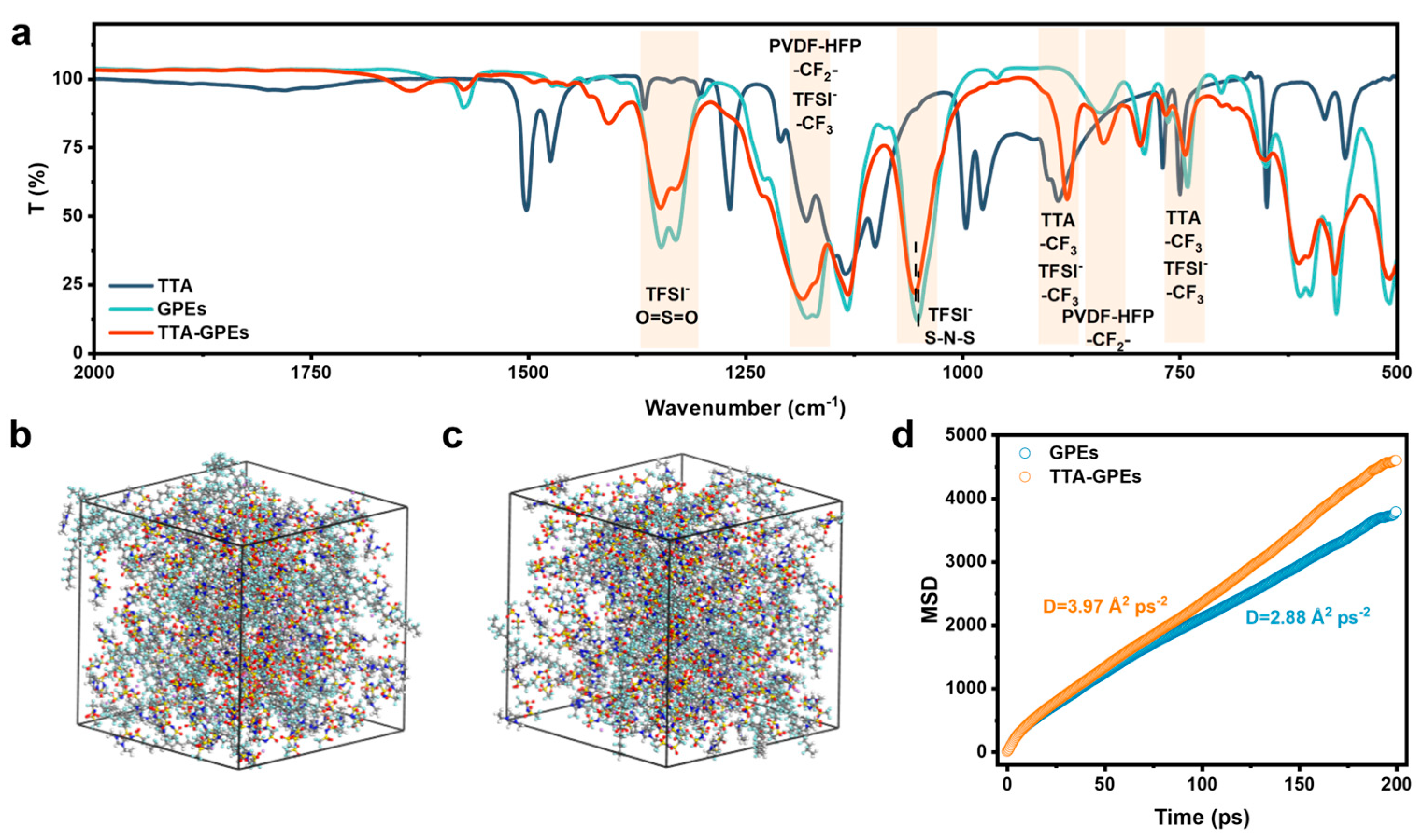
+ transference number within the modified electrolytes, structural and theoretical analyses combining Fourier-Transform Infrared Spectroscopy (FTIR) and molecular dynamics (MD) simulations were executed. As illustrated in the comprehensive FTIR spectra (
Figure 4a), the introduction of the TTA additive profoundly reshapes the microscopic chemical environment within the GPE matrix. Specifically, the characteristic stretching vibration of the C-F bond structurally shifts from 1178 cm
−1 in the baseline GPEs to 1183 cm
−1 in the TTA-GPEs. Accompanied by the distinct variation in O=S=O bands at ~1350 cm
−1, the stretching vibration of the S–N–S bond belonging to the TFSI
− anion also undergoes a dramatic shift from 1051 cm
−1 to 1154 cm
−1. These massive band evolutions fundamentally reflect the redistribution of the electron cloud density within the anions, providing compelling experimental proof that the electron-rich triazole ring of TTA acts as a robust Lewis base to competitively coordinate with Li
+ or TFSI
−. Consequently, this competitive interaction successfully dissociates the strongly bound Li
+−TFSI
− contact ion pairs and aggregates, liberating an abundance of free Li
+ to participate in bulk conduction.
Beyond the macroscopic salt dissociation, TTA simultaneously exerts a strong molecular plasticizing effect on the polymer matrix and reconstructs the primary solvation sheath. Notably, the characteristic peak corresponding to the crystalline phase of the PVDF-HFP backbone exhibits a noticeable redshift from 848 cm−1 down to 838 cm−1. This downshift unambiguously indicates that the incorporation of TTA disturbs the intrinsically highly ordered crystalline domains of PVDF-HFP, thereby expanding the proportion of the amorphous phase, which is widely recognized as the universal pathway for segmental Li+ hopping. Furthermore, in the low-frequency fingerprint region, the intrinsic isolated sharp peak of the -CF3 group in pure TTA at 749 cm−1, along with the coupled TFSI−/PVDF-HFP band at 741 cm−1, continuously merges and re-establishes at 744 cm−1 within the composite film. The quenching and integration of TTA’s original free-state modes intimately confirm that the additive does not exist as isolated molecules in the matrix, but rather deeply anchors into the Li+ solvation architecture to construct a homogenized coordination network.
To theoretically validate these robust experimental structural observations, classical MD simulations were constructed to trace the dynamic transport behavior of lithium ions across the matrices (
Figure 4b,c). The Mean Square Displacement (MSD) curve over simulated time inherently evaluates the thermodynamic mobility of Li
+. As explicitly plotted in
Figure 4d, the pristine GPE system exhibits relatively sluggish diffusion kinetics with a slope (equivalent to the diffusion coefficient) of 2.88 Å
2 ps
−1. In extraordinary contrast, the TTA-GPE system displays a significantly steeper MSD slope of 3.97 Å
2 ps
−1, representing an exceptional enhancement in the intrinsic Li
+ diffusion parameter. Collectively, the theoretical MD perfectly corroborate the multi-dimensional FTIR structural insights: the multifunctional TTA explicitly unties the tight electrostatic binding between Li
+ and TFSI
− while concurrently suppressing localized polymer crystallinity. This synergistic modulation orchestrates a highly unblocked, three-dimensional fast-track pathway for Li
+ flux, establishing a fundamental microscopic explanation for the superior mass transport and electrochemical kinetics achieved in the solid-state cells.
3.4. Investigation of the Interfacial Compatibility Between TTA-GPEs and the Lithium Anode
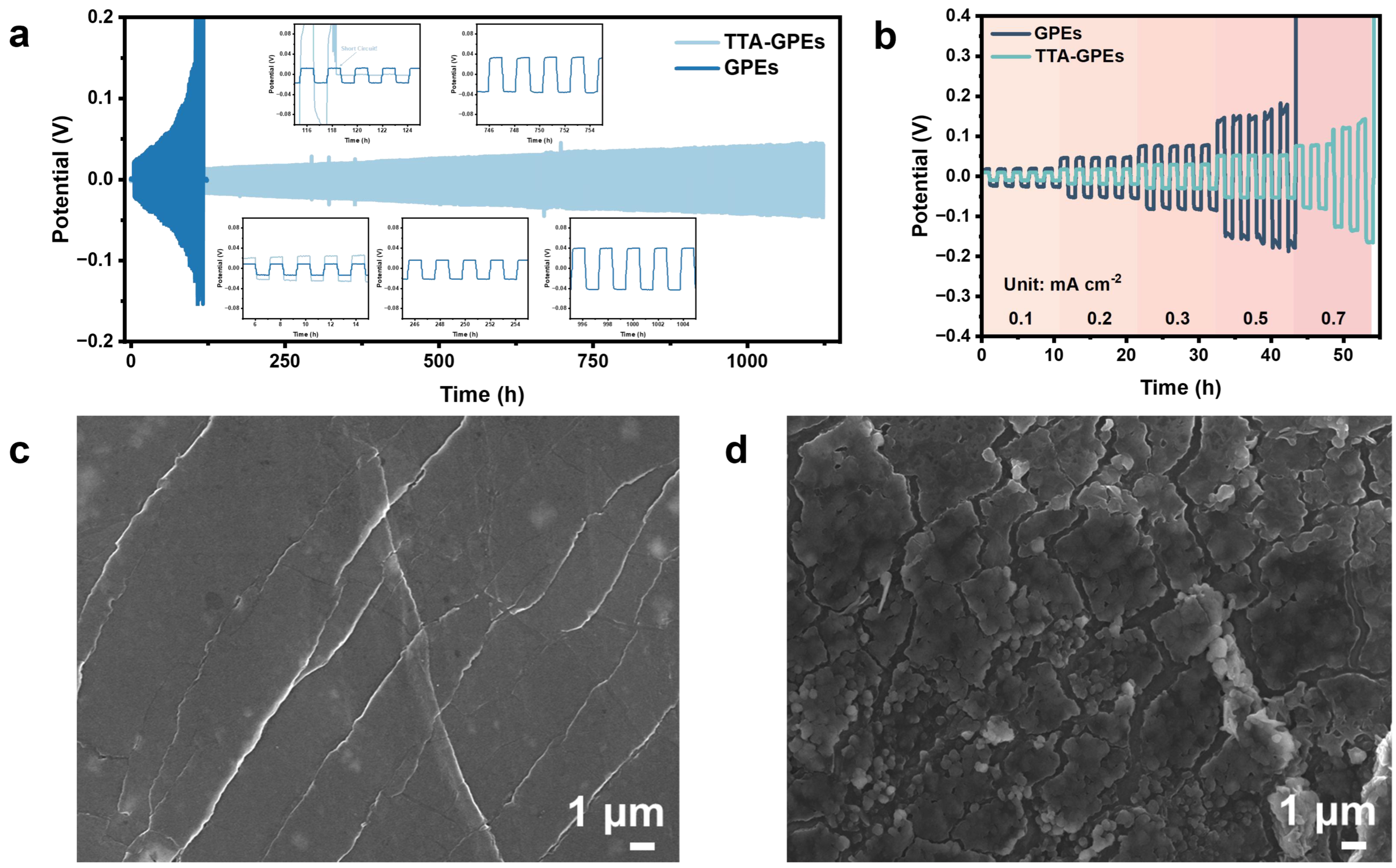
To rigorously investigate the dynamic protective capability of TTA-GPEs toward the lithium metal anode under severe operating conditions, Li//Li symmetric cells were subjected to long-term constant current cycling and critical current density (CCD) assessments at an elevated temperature of 80 °C.
As detailed in the long-term cycling profiles (
Figure 5a), under the condition of 0.1 mA cm
−2 at 80 °C, the symmetric cell utilizing TTA-GPEs exhibits a low initial polarization voltage of merely 13 mV. Crucially, the polarization remains highly stable, with the voltage profiles displaying regular rectangular waveforms without any distinct signs of increased polarization or short-circuiting over a lifespan exceeding 1100 h. In sharp contrast, the GPE-based counterpart displays a higher initial polarization of 22 mV and suffers a catastrophic failure at approximately 118 h, manifested by a sudden voltage spike followed by a precipitous drop. This characteristic voltage fluctuation signifies that unchecked lithium dendrite growth has penetrated the mechanically insufficient electrolyte membrane, triggering an internal micro-short circuit. These results compellingly demonstrate that the TTA molecules induce the formation of a robust SEI film. This interface retains exceptional mechanical toughness and chemical inertness even at elevated temperatures, effectively suppressing the formation of “dead lithium” and vertical dendrite growth, ultimately enabling uniform lithium deposition and stripping at the interface.
The CCD test (
Figure 5b) further quantifies the high-rate capability of the electrolytes. As the current density is increased in a stepwise manner, the polarization voltage of the Li/GPE/Li cell rises sharply, exhibiting high internal resistance characteristics consistent with Ohmic behavior. Upon reaching a current density of 0.7 mA cm
−2, the voltage profile of the Li/GPE/Li cell spikes dramatically, resulting in immediate failure. In sharp contrast, the Li/TTA-GPE/Li cell demonstrates significantly lower overpotentials across all tested current densities, maintaining smooth voltage plateaus even under high-load conditions and achieving stable cycling at 0.7 mA cm
−2. This superior CCD performance is directly ascribed to the elevated
and rapid interfacial kinetics enabled by the TTA modification. The high transference number effectively delays the depletion of lithium-ion concentration near the interface, thereby ensuring uniform lithium deposition under high-current regimes. This improvement not only broadens the operational current window of the battery but also lays a solid foundation for the fast-charging application of high-energy-density solid-state batteries.
To elucidate the microscopic mechanism governing the regulation of the SEI by TTA, the morphology of the post-cycling lithium metal anodes was scrutinized via SEM (
Figure 5c,d). A comparative analysis reveals that the lithium surface cycled in pristine GPEs undergoes severe pulverization and brittle fracture, being riddled with deep cracks and loose, porous “mossy” lithium structures. Such a rugged morphology is not only indicative of continuous and aggressive parasitic reactions between the electrolyte and the lithium metal—which induce drastic volume fluctuations—but also signals a significant accumulation of “dead lithium” and a heightened risk of dendrite penetration. In sharp contrast, the lithium anode protected by TTA-GPEs exhibits a dense, planar, and smooth deposition morphology, displaying only faint grain boundaries without any distinct cracks or dendritic protrusions. These findings demonstrate that the TTA-induced SEI layer possesses exceptional mechanical flexibility and homogeneity, allowing it to effectively accommodate the volume changes associated with the lithium plating/stripping process and guide the uniform deposition of lithium ions.
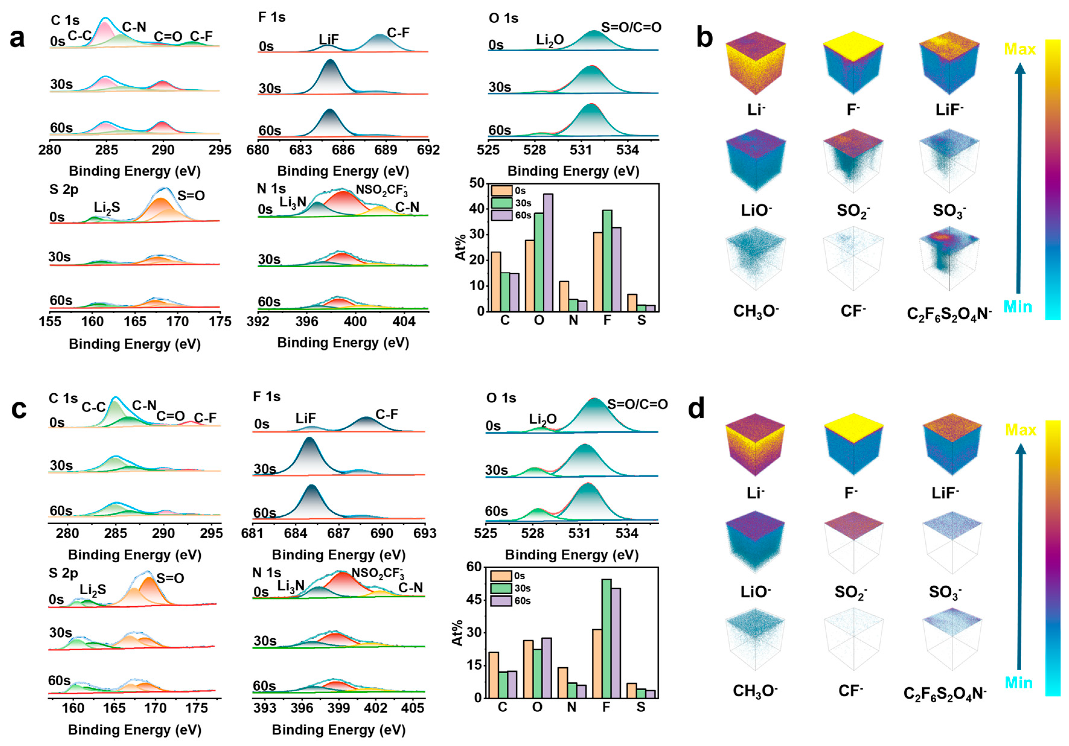
To thoroughly elucidate the microscopic chemical mechanism by which the TTA additive regulates the composition and structure of the SEI, XPS with depth profiling was conducted on the post-cycling lithium metal surfaces (
Figure 6a,c). The C 1s spectra clearly reveal that the C–C peak, which primarily corresponds to organic species resulting from electrolyte decomposition, gradually diminishes in intensity as the argon ion etching depth increases from 0 s to 60 s. This trend indicates that organic components are predominantly enriched on the electrolyte side (outer layer) of the SEI, while the inner interface proximal to the lithium metal contains a reduced fraction of organic matter. In the F 1s spectra, both systems display signals corresponding exclusively to organic fluorine (C–F) and inorganic LiF; however, their distributions differ markedly. At the near-electrolyte surface (0 s), the GPE sample exhibits a relatively high proportion of C–F bonds. Although LiF is present, atomic quantification reveals that its concentration is significantly lower than in the modified sample, suggesting that the baseline electrolyte is prone to uncontrolled decomposition of solvents or polymer backbones at the distal interface. Conversely, in the TTA-GPE system, the LiF peak dominates even at the outermost surface following TTA addition. As etching proceeds toward the lithium side, the C–F peak virtually disappears while the LiF content further increases. This confirms that TTA successfully induces the formation of a stable, inorganic inner layer rich in high-modulus LiF, which effectively blocks subsequent interfacial side reactions. Further refined analysis of the O 1s, S 2p, and N 1s spectra unveils the specific evolutionary trends in the inorganic components. In the O 1s spectra, the content of Li
2O—a critical inorganic constituent—is significantly elevated in the SEI of the TTA-modified system. This mechanically robust oxide greatly enhances the physical stability of the SEI film. Comparative analysis of the S 2p spectra provides vital clues regarding anion decomposition pathways: on the near-lithium side (60 s) of the TTA-modified sample, stronger signals for Li
2S and S=O (corresponding to TFSI
−) are detected. This indicates that the participation of TTA not only optimizes the decomposition pathway, promoting the conversion of TFSI
− into highly conductive Li
2S, but also preserves a portion of the anion structure, thereby mitigating the excessive and wasteful consumption of lithium salts. In contrast, the baseline GPE sample exhibits a significantly lower proportion of S=O at the outer surface (0 s) compared to TTA-GPEs, confirming that TFSI
− undergoes severe parasitic decomposition at the unprotected interface. Furthermore, the N 1s spectra reflect the direct participation of TTA molecules in the film-forming reactions, which significantly promotes the generation of the fast ion conductor Li
3N.
In summary, the XPS analysis provides compelling evidence that the incorporation of TTA rapidly modulates the chemical composition of the SEI. By inducing the formation of a composite interfacial layer characterized by reduced organic content and an abundance of inorganic species—such as Li2O, LiF, Li2S, and Li3N—during the initial charge/discharge stages, TTA constructs an ideal interface that possesses both high mechanical strength and rapid ion transport capabilities. Consequently, this fundamentally alleviates the continuous parasitic side reactions between the electrolyte and the lithium metal.
The three-dimensional (3D) spatial distribution and depth profiling results obtained via TOF-SIMS (
Figure 6b,d) provide direct microscopic insights into the regulatory role of the TTA additive on the lithium metal/electrolyte interfacial structure. A comparative analysis between the baseline GPEs and the TTA-GPEs reveals striking differences in interfacial architecture. In the baseline GPE system, the secondary ion signals on the lithium surface exhibit a highly heterogeneous distribution. The secondary ions characteristic of LiF appear as discrete, isolated islands or punctate spots within the 3D reconstruction, accompanied by low signal intensity. This indicates that the resulting inorganic interfacial layer suffers from poor coverage and a loose, non-compact morphology. Conversely, substantial signals attributed to organic components (e.g., CH
3O
−) are diffusely distributed throughout the spatial volume and are particularly enriched in the near-surface region. This evidence points to severe parasitic decomposition of solvent molecules, resulting in the formation of an amorphous SEI layer dominated by organic polymeric species. Furthermore, distinct signals corresponding to decomposition fragments of the TFSI
− anion (e.g., SO
2−, SO
3−, and C
2F
6S
2O
4N
−) are prevalent, aligning well with the complex side-reaction products identified via ex situ XPS. Collectively, the GPE interface manifests as a porous, “organic–inorganic intermixed” structure, which is structurally insufficient to effectively suppress lithium dendrite propagation.
In sharp contrast, the interfacial structure of the TTA-GPE system undergoes a fundamental transformation. The 3D TOF-SIMS imagery clearly demonstrates that the incorporation of TTA induces the formation of a dense SEI film characterized by a distinct layered architecture. Proximal to the lithium metal surface, intense and highly homogeneous LiF
− signals are observed. These species are spatially continuous, constructing a compact inorganic inner layer that covers nearly the entire electrode surface. This observation corroborates the “LiF-rich inner layer” feature identified in the XPS depth profiling. Concurrently, signals representing organic components (CH
3O
−) are virtually suppressed within this region, appearing only faintly at the outer layer near the electrolyte. This attests to the high priority and selectivity of the TTA-participated film-forming reactions, which effectively preclude the accumulation of organic species. Notably, the signal intensity of components related to TFSI
− decomposition (e.g., SO
2− and SO
3−) is negligible in the TTA-GPE system, suggesting that the robust SEI formed by TTA prevents the excessive reduction of lithium salts, thereby enhancing their utilization efficiency. Furthermore, the 3D spatial composition analysis of the near-surface layer via depth profiling (
Figure S7) confirms that TTA-GPEs facilitate the generation of a dense and uniform SEI on lithium metal during high-temperature electrochemical processes, effectively mitigating continuous parasitic reactions. The 2D distribution maps of surface components (
Figure S6) also illustrate that while the SEI formed by GPEs exhibits marked heterogeneity, the SEI derived from TTA-GPEs displays significantly superior homogeneity across the two-dimensional plane. The depth profiling curves (
Figure S5) reveal that the TTA-GPEs’ interfacial layer possesses a steep compositional gradient, transitioning rapidly from a LiF-rich dense inner layer to the electrolyte bulk. This well-defined bilayer architecture endows the interface with superior mechanical robustness and ionic selectivity, serving as the microstructural foundation for dendrite-free, long-term cycling.
Density functional theory (DFT) calculations further elucidate the interfacial reaction mechanism of TTA (
Figure S8). Exhibiting the lowest Lowest Unoccupied Molecular Orbital (LUMO) energy level, TTA is energetically favored to react preferentially at the interface, thereby constructing a stable SEI in situ.
In summary, the TOF-SIMS investigations provide compelling visual evidence for the interfacial regulation mechanism of the TTA additive. Acting as an efficient film-forming promoter, TTA undergoes preferential reduction and selective reaction with the active lithium surface to in situ construct an ultrathin, dense inorganic SEI film with a distinct hierarchical structure. This mechanism suppresses the generation of organic byproducts and the nucleation of lithium dendrites at the source, thereby substantially enhancing the cycling stability of the lithium metal anode under high-temperature conditions.
3.5. Performance Validation and Mechanistic Analysis of TTA-GPEs in Solid-State Batteries
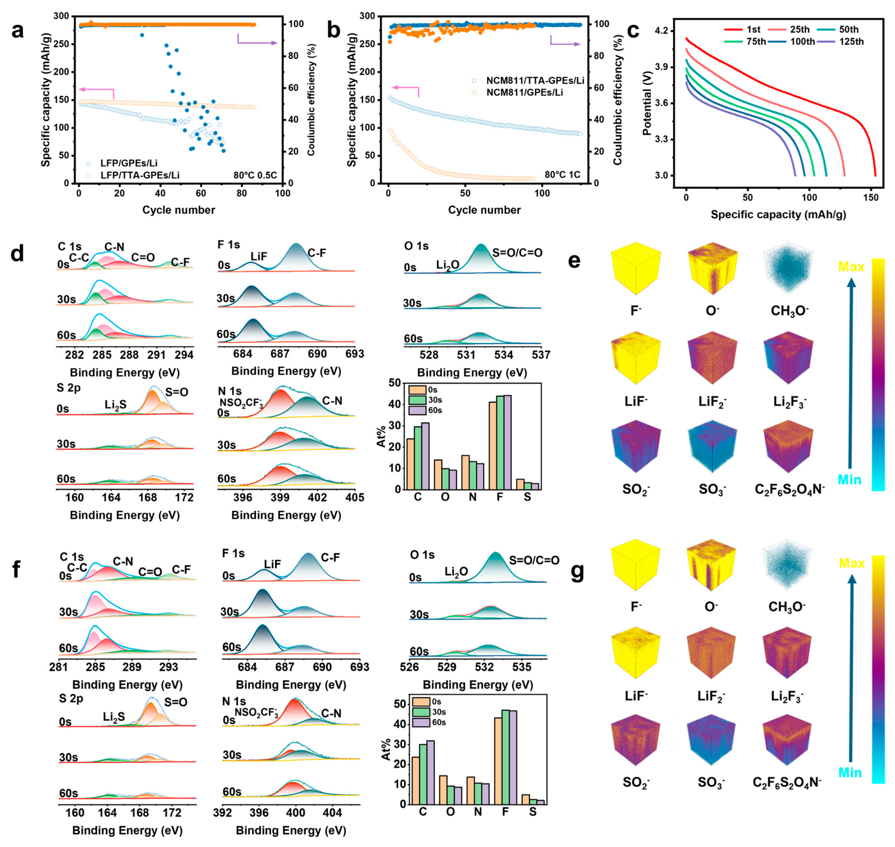
To evaluate the practical applicability of the electrolytes in full-cell configurations, LiFePO
4 (LFP)//Li and NCM811//Li batteries were assembled and tested. In the LFP//Li cells (
Figure 7a) cycled at 80 °C and 0.5 C, the TTA-GPE system exhibits superior stability. After 86 cycles, it retains 93.13% of its capacity with an average Coulombic efficiency (CE) of 99.92%. Such an exceptionally high CE signifies that the CEI induced by TTA possesses excellent electronic insulation and ionic conductivity, effectively mitigating continuous parasitic reactions between the electrolyte and the electrode. In contrast, the capacity retention of the GPE-based cell drops to a mere 76.05% after 50 cycles, beyond which the cell displays erratic cycling behavior. The average CE over the first 50 cycles is limited to 93.54%, indicating severe interfacial side reactions and irreversible lithium loss at elevated temperatures, which precipitate a drastic deterioration in reaction kinetics. This enhancement in capacity retention and CE stems from the rapid formation of an effective interfacial layer by TTA during the initial cycles, which stabilizes the interface. This conclusion is further corroborated by the performance of the NCM811//Li cells (
Figure 7b,c). Under the rigorous conditions of 80 °C and 1 C, the NCM811/TTA-GPE/Li cell delivers a high initial specific capacity of 153.6 mAh g
−1. After 125 cycles, it maintains a capacity retention of 57.68% with an impressive average CE of 99.43%. Conversely, the NCM811/GPE/Li cell yields a significantly lower initial specific capacity of 94.9 mAh g
−1 and suffers from rapid and continuous capacity decay. After only 35 cycles, the retention plummets to 20.23%, with an average CE of just 96.89%. Such poor initial capacity and rapid degradation illustrate that, in the absence of TTA protection, high temperatures trigger aggressive oxidative decomposition of the electrolyte on the NCM811 surface. This leads to the formation of a highly resistive, inert layer, thereby accelerating cell failure.
To elucidate the evolution mechanism of TTA on the NCM811 cathode surface during high-temperature electrochemical processes, the CEI formed after three cycles was comprehensively characterized via XPS and TOF-SIMS (
Figure 7d,f). While the XPS results indicate that the chemical composition of the CEI is qualitatively similar across both electrolytes, a detailed comparison of peak intensities reveals significant structural differences. In the F 1s spectra of the TTA-modified system, the CEI exhibits a higher abundance of LiF components at the inner interface proximal to the active material, indicating that TTA participates in interfacial reactions during the initial stages of high-temperature cycling to promote the formation of a LiF-rich passivation layer. Furthermore, the N 1s depth profile for the baseline GPE-derived CEI shows a uniform distribution of nitrogen species throughout the layer, whereas the CEI generated by TTA-GPEs displays a distinct gradient with significantly lower nitrogen content in the inner layer compared to the outer layer. This trend, which is corroborated by the marked attenuation of sulfur signals in the S 2p spectra of the TTA-GPE system, suggests the formation of a self-limiting, stable CEI that effectively inhibits further reactions between the electrolyte and the cathode, thereby blocking the deposition of decomposition products.
The three-dimensional depth profiling obtained via TOF-SIMS (
Figure 7e,g,
Figures S9 and S10) provides a visual reconstruction of the compositional architecture within the CEI, further validating the XPS findings. In the baseline GPE system, signals corresponding to organic decomposition products (CH
3O
−) are significantly higher, while inorganic signals (such as LiF
−, LiF
2−, and Li
2F
3−) are relatively weak and heterogeneous. This points to a loose, porous CEI structure that fails to effectively passivate the highly active NCM811 surface, a conclusion supported by 2D surface distribution maps showing marked concentration variations for sulfur-containing fragments. In fundamental contrast, the TTA-GPE system exhibits a significantly lower content of organic species and a higher, more uniform distribution of inorganic lithium fluorides. The specific distribution of the C
2F
6S
2O
4N
− fragment offers critical evidence: while the GPE system shows a continuous permeation of this species, the TTA-GPE system displays a sharp concentration discontinuity. This definitively proves that TTA decomposes to form a compact CEI that physically barricades the electrode, preventing continuous electrolyte oxidation.
Density functional theory (DFT) calculations further clarify this mechanism, revealing that TTA possesses the highest Highest Occupied Molecular Orbital (HOMO) energy level among the electrolyte components (
Figure S8). This electronic property dictates its preferential oxidation at the cathode/electrolyte interface, facilitating the in situ construction of a stable protective layer.
In summary, the incorporation of TTA fundamentally ameliorates the interfacial evolution at the electrode/electrolyte boundary during high-temperature cycling. Acting as a preferential film-forming agent, TTA induces the in situ generation of SEI and CEI layers that are enriched with inorganic components (LiF, Li2O, and Li3N) and depleted of organic byproducts. These robust interfaces mitigate continuous parasitic reactions between the electrolyte and the electrodes, thereby significantly enhancing the comprehensive performance of the battery.