Article

Thermal Runaway Hazards of Ternary Lithium-Ion Batteries Under Different Ambient Pressure Environments

1
College of Civil Aviation Safety Engineering, Civil Aviation Flight University of China, Guanghan 618307, China
2
Civil Aircraft Fire Science and Safety Engineering Key Laboratory of Sichuan Province, Civil Aviation Flight University of China, Guanghan 618307, China
*
Author to whom correspondence should be addressed.
Batteries 2025, 11(9), 339; https://doi.org/10.3390/batteries11090339
Submission received: 29 July 2025 / Revised: 4 September 2025 / Accepted: 7 September 2025 / Published: 12 September 2025
(This article belongs to the Section Battery Performance, Ageing, Reliability and Safety)

Abstract

Aiming for the safety requirements of aviation transportation of lithium-ion batteries, the thermal runaway characteristics of ternary lithium-ion batteries in a low ambient pressure environment were systematically explored. The results showed that the low ambient pressure significantly reduced the peak temperature of battery thermal runaway. The critical trigger temperature was increased by about 30 °C because of the suppression of convective heat transfer and side reactions inside the battery by the low ambient pressure. At 50 kPa ambient pressure, the injection stage of batteries with 100% SOC and 50% SOC were delayed by 16 s and 99 s, respectively, and the combustion intensity was also significantly weakened. The violent eruption of the battery with 100% SOC caused the rupture of the aluminum–plastic film, and the battery with 0% SOC only expanded inward. Constant ambient pressure (96 kPa) and high SOCs (≥50%) are a high-risk combination, and fire monitoring needs to be strengthened. Low ambient pressure (≤50 kPa) and low SOCs (≤30%) are less dangerous for thermal runaway. It is suggested that the SOC should not be higher than 50% in aviation transportation. This work provides an important reference for the safety of lithium-ion batteries in aviation transportation.

Graphical Abstract

1. Introduction

Lithium-ion batteries are widely used in various energy storage systems because of their excellent electrochemical performance [1,2]. However, there are great security risks in their use and transportation. Lithium-ion batteries are prone to abnormal energy release under external abuse conditions, which leads to thermal runaway [3,4]. Common induced forms of battery thermal runaway include thermal abuse, internal short circuit, external short circuit, overcharge, overdischarge, and mechanical abuses [5,6,7,8]. Zhao et al. [9] used the improved large-scale accelerating rate calorimeter combined with a customized sealed pressure vessel to deeply study the thermal runaway hazard characteristics of the 18650 lithium-ion battery. Jindal et al. [10] reviewed the effects of initial conditions (state of charge, overcharge, and aging) and battery design (geometry, material, and capacity) on the severity of thermal runaway. Thermal runaway became more serious in batteries with a high state of charge, overcharge, and aging, and the mechanism of thermal runaway mainly depends on the battery design. The fire hazard was quantified by the heat release rate.
In recent years, researchers have carried out the thermal runaway characteristics of lithium-ion batteries in low air pressure environments [11,12,13]. Liu et al. [14] studied the combustion and explosion behavior of lithium-ion batteries under different pressure conditions. Compared with the normal pressure conditions, the low-pressure environment resulted in a longer combustion duration, a higher combustion response temperature, and a lower mass loss rate. Fu et al. [15] revealed the influence of environmental pressure on battery thermal runaway behavior through the thermal radiation induction experiment in a low-pressure chamber. Under the standard atmospheric pressure (101 kPa), the battery burned violently, with explosion after thermal runaway. However, in the medium- and low-pressure environments (40–90 kPa), only jet flame was produced without explosion. When the pressure was dropped to 30 kPa, the phenomenon of jet flame disappeared completely. Wang et al. [16] established the quantitative relationship between the heat transfer coefficient and environmental pressure, and confirmed that the convective heat transfer coefficient was directly proportional to the square of environmental pressure. Jia et al. [17] studied the thermal runaway propagation behavior of a 18650 battery under different environmental pressures. With the decrease in environmental pressure, the opening time of the battery safety valve showed an early trend, and the exothermic reaction intensity in the process of thermal runaway was significantly suppressed. Chen et al. [18] investigated the thermal runaway characteristics of lithium-ion batteries at an ambient pressure ranging from 95 kPa to 20 kPa. With the decrease in environmental pressure, the heat release rate, battery surface temperature, peak concentration of CO2, and mass loss were decreased.
Under a low air pressure environment, the side reaction at the interface between electrode and electrolyte is intensified, and the rupture of the solid electrolyte interface (SEI) film is accelerated, thus promoting the occurrence of gas generation and internal short circuit of lithium-ion batteries. Although the existing research has systematically revealed the influence law of low-pressure environments on the macro-behavior and characteristic parameters of the thermal runaway of lithium-ion batteries, the research on the evolution mechanism of the internal microstructure and its structure–activity relationship with thermal runaway behavior under low ambient pressure conditions are still insufficient. In particular, the lack of experimental research on the coupling mechanism between air pressure and state of charge has seriously restricted the design of battery safety systems in aviation and high-altitude application scenarios. This study focused on the safety requirements in special low-pressure environments such as aviation transportation and high-altitude areas. The dynamic pressure chamber was used in the experiment, and nine test conditions of three ambient pressures (96 kPa, 70 kPa, and 50 kPa) and three SOCs (100% SOC, 50% SOC, and 0% SOC) were constructed. It was of great significance to develop an effective safety protection system for aviation environments by revealing the relationship between the degradation mechanism of battery materials and thermal runaway behavior.

2. Experimental Design

2.1. Cell Samples

Before the thermal runaway experiments, the BT-2016D battery test system (manufactured in Hubei) was used to perform two charge–discharge cycles according to the standard procedure. The schematic diagram of the experimental setup for the pouch ternary lithium-ion battery is shown in Figure 1a. The lithium-ion battery selected for the battery thermal runaway experiment has a capacity of 5000 mAh and dimensions of 115 × 65 × 4 mm3.

2.2. Experimental Setup

The experimental platform consists of a variable pressure chamber, a battery test system (BT-2016D, (BT-2016D, Hubei Lanbo New Energy Equipment Co., Ltd., Wuhan, China), a stainless-steel heating plate (power: 400 W), a data recorder (Agilent, Keysight DAQ970A, Santa Clara, CA, USA), a K-type armored thermocouple (measuring range: 0~1200 °C), and a digital camera (HIKVISION 3T46WD-I3, Hangzhou, China). The combustion chamber was equipped with an observation window made of explosion-proof glass. A 5000 mAh ternary lithium-ion pouch battery was placed in the variable pressure chamber, with the heating plate located on the side of the battery and secured by steel wires. The camera recorded the phenomena of the thermal runaway process. A K-type thermocouple was arranged on the groove surface, located at the center of the battery surface.
As shown in Figure 1b, the internal dimensions of the dynamic pressure-variable chamber are 2 m × 2 m × 2 m, with an effective volume of 8 m3. An inner chamber can be constructed inside the main chamber according to experimental size requirements. The pressure adjustment range was between 10 kPa and 101 kPa, with an error controlled within ±0.1 kPa. The variable pressure chamber monitored the target pressure and inlet/outlet gas flow rate in real time, collected the air pressure data, and had a monitoring alarm and other functions.
As shown in Table 1, in this experiment, the materials used for the selected ternary lithium-ion battery were made of anodes, cathodes, and electrolytes. The anode material was graphite, and cathode material was Li(Ni0.5Co0.3Mn0.2)O2, in which the molar ratio of nickel, cobalt, and manganese was 5:3:2, and the electrolyte was composed of LiPF6, ethylene carbonate, and methyl ethylene carbonate.
To investigate the thermal runaway characteristics of the lithium-ion battery at different scenes, three ambient pressures (96 kPa, 70 kPa, 50 kPa) and three state of charge (100% SOC, 50% SOC, 0% SOC) were selected. The selection of 96 kPa, 70 kPa, and 50 kPa was directly related to the altitude and cargo space environment. A pressure of 96 kPa (about 500 m altitude) simulated ground or low-altitude transportation, as the control group. A pressure of 70 kPa (about 3000 m altitude) corresponded to the typical air pressure of an aircraft cargo hold, so as to ensure the safety and stability of the battery in regular aviation transportation. A pressure of 50 kPa (about 5500 m altitude) simulated the situation of pressure loss or non-pressurized transportation in the cargo hold. Because the experiment was conducted in Guanghan City, Sichuan Province, China (500 m altitude, about 96 kPa atmospheric pressure), 96 kPa was chosen as the control group to truly reflect the experimental conditions, which was slightly lower than the standard atmospheric pressure (101.3 kPa). Therefore, nine experimental conditions were adopted, including SOC100%-96kPa, SOC100%-70kPa, SOC100%-50kPa, SOC50%-96kPa, SOC50%-70kPa, SOC50%-50kPa, SOC0%-96kPa, SOC0%-70kPa, and SOC0%-50kPa. For example, SOC100%-96kPa represented the condition corresponding to SOC 100% and 96kPa.

2.3. Materials Characterizations

The crystalline phase of the residue of the lithium-ion battery after thermal runaway was determined by a Rigaku Ultima IV X-ray diffractometer (Rigaku Corporation, Tokyo, Japan), equipped with Cu Kα radiation, in the 2θ range from 5° to 85°. Then, the crystalline phases were identified with the help of a database. The microstructure and element composition of the residue of the lithium-ion battery after thermal runaway was investigated by SEM-EDS analysis using an Apreo 2C scanning electron microscope (SEM, Thermo Scientific, Waltham, USA) coupled with a ULTIM Max65 energy dispersive spectroscopy (EDS, Oxford Instruments, High Wycombe, UK) detector. The surface of the sample was sprayed with gold before testing.

3. Results and Discussion

3.1. Thermal Characteristic of Lithium-Ion Battery

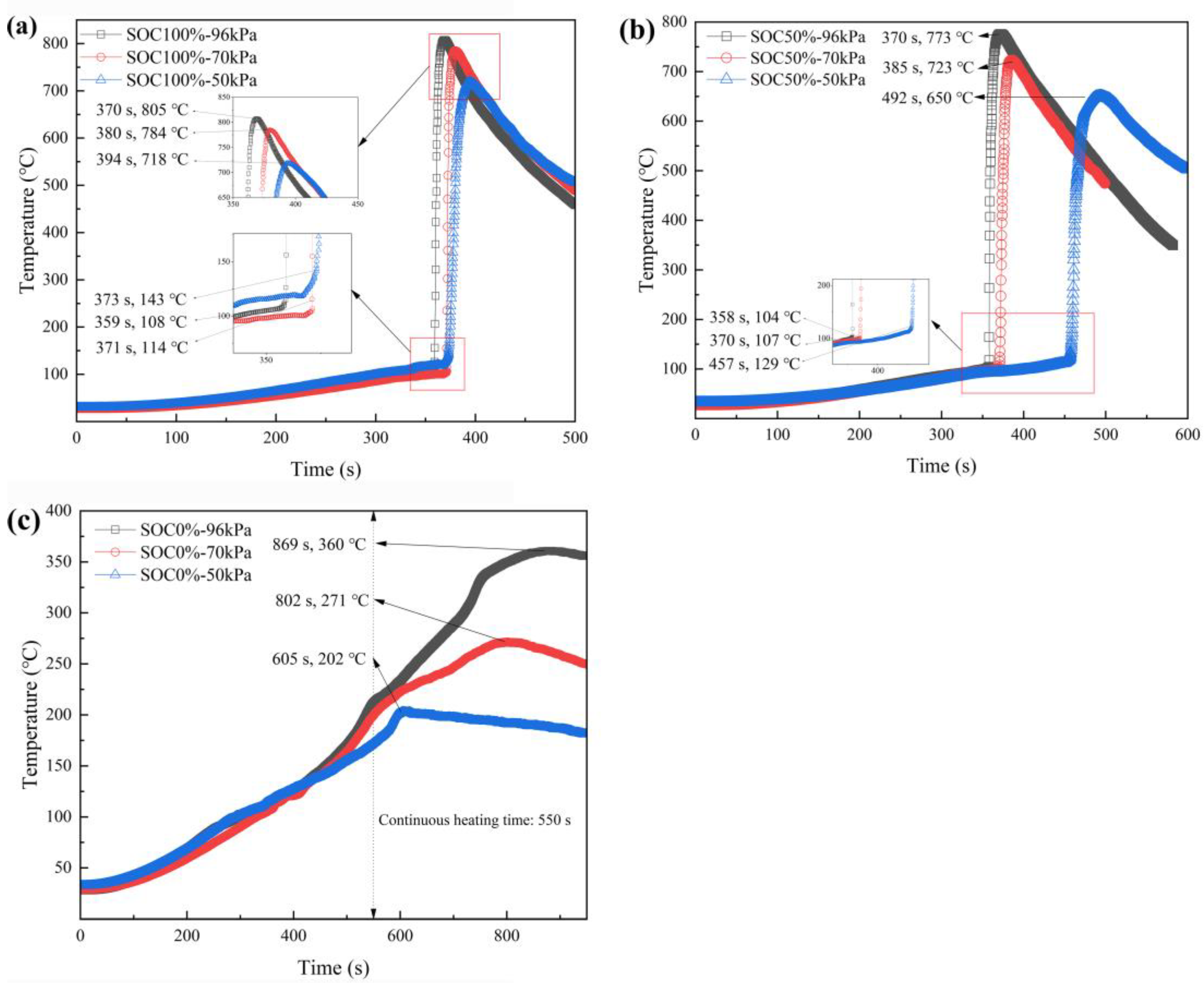
The surface temperature of the battery is a key parameter reflecting the intensity of thermal runaway reactions. A comparative analysis was conducted on the battery temperature under different ambient pressures. As shown in Figure 2, at 100% SOC, the peak temperatures of the battery at 96 kPa, 70 kPa, and 50 kPa were 805 °C, 784 °C, and 718 °C, respectively. For 50% SOC, the peak temperatures of the battery were 773 °C, 723 °C, and 650 °C, respectively. For 0% SOC, the peak temperatures of the battery were 360 °C, 271 °C, and 202 °C, respectively. Under normal pressure, the explosion was more violent and released more energy. With the decrease in environmental pressure, the peak temperature of the battery showed a downward trend, which was mainly due to the slow combustion rate and flame thermal feedback [19]. By analyzing the battery temperature data, the critical thermal runaway temperature was determined where the temperature rose sharply. For 100% SOC and 50% SOC, with the decrease in environmental pressure, the critical thermal runaway temperature showed an upward trend, and the trigger time of thermal runaway was correspondingly prolonged, while the peak thermal runaway temperature showed a downward trend. Thus, the environmental pressure seriously affected the harm degree of battery thermal runaway.
As shown in Figure 2a,b, the temperature curve showed a similar trend, which was roughly divided into three stages: Stage I, Stage II, and Stage III. In the first stage, under the same heating power, the curve was almost consistent with the consistent temperature trend, and the heating duration was prolonged with the decrease in ambient pressure. Although their duration was different, the temperature rise in the battery mainly came from the heating plate.
At the beginning of Stage II, the temperature experienced a sudden change and reached its peak in a very short time. The internal heat release rate far exceeded the rate of heat dissipation to the environment. Driven by heat accumulation and the internal and external pressure difference, the battery reached the critical thermal runaway state. With the decrease in pressure, the peak temperature of the battery decreased and the duration of the second stage increased. The thermal runaway trigger temperature (TTR) varied greatly in different pressure environments, especially at 50 kPa, which was significantly higher than that at 96 kPa and 70 kPa. At 100% SOC, the TTR at 50 kPa was 29 °C and 37 °C higher than that at 96 kPa and 70 kPa, respectively. At 50% SOC, it was 25 °C and 27 °C higher, respectively, which proved the important influence of ambient pressure on thermal runaway characteristics. This was also consistent with the previous related research [16,17,20]. In Stage III, the battery temperature showed a downward trend due to the comprehensive effect of heat transfer between the battery and the environment. On the one hand, when the thermal feedback was weakened, the thermal runaway process entered the disappearance stage. On the other hand, under the condition of low ambient pressure, the convective heat loss between the battery and its environment was reduced [21].
Figure 2a,b show that the duration of Stage I and Stage II was significantly different in a low ambient pressure environment. With the decrease in ambient pressure, the peak temperature of the battery decreased, and the whole temperature curve moved backward. That is, the response time of thermal runaway was significantly delayed, which proved that environmental pressure seriously affected the thermal runaway temperature characteristics of lithium-ion batteries. Compared with the ambient pressure of 96 kPa and 70 kPa, the trigger time was obviously delayed at an ambient pressure of 50 kPa. In 100% SOC, the trigger time was delayed from 96 kPa 359 s to 373 s. In 50% SOC, the trigger time was delayed from 96 kPa 358 s to 457 s. This was mainly due to two reasons. For one thing, thermal runaway was a process involving many violent oxidation reactions, many of which depended on oxygen, and the decrease in outside air pressure made the oxygen supply insufficient, thus delaying the internal exothermic reaction rate. Additionally, the low air pressure environment aggravated the evaporation loss of the electrolyte, resulting in the decrease in residual electrolytes within the battery, which reduced the exothermic rate of the electrolyte decomposition reaction. As shown in Figure 2c, the lithium-ion battery with 0% SOC had not experienced thermal runaway. The heating plate only operated for 550 s under the ambient pressures of 96 kPa, 70 kPa, and 50 kPa, and the peak temperatures of battery were 360 °C, 270 °C, and 202 °C, respectively. No sudden temperature fluctuation was observed, and the peak temperature appeared obviously earlier. With the decrease in ambient pressure, the peak temperature of the battery showed a downward trend, which was mainly caused by the weakening of the air convection heat dissipation ability, the decrease in the boiling point of the electrolyte, and the deterioration of the thermal stability of the SEI film and cathode materials. These studies showed that the peak temperature of the battery decreased as the ambient pressure decreased, which was consistent with the previous literature [19,20].
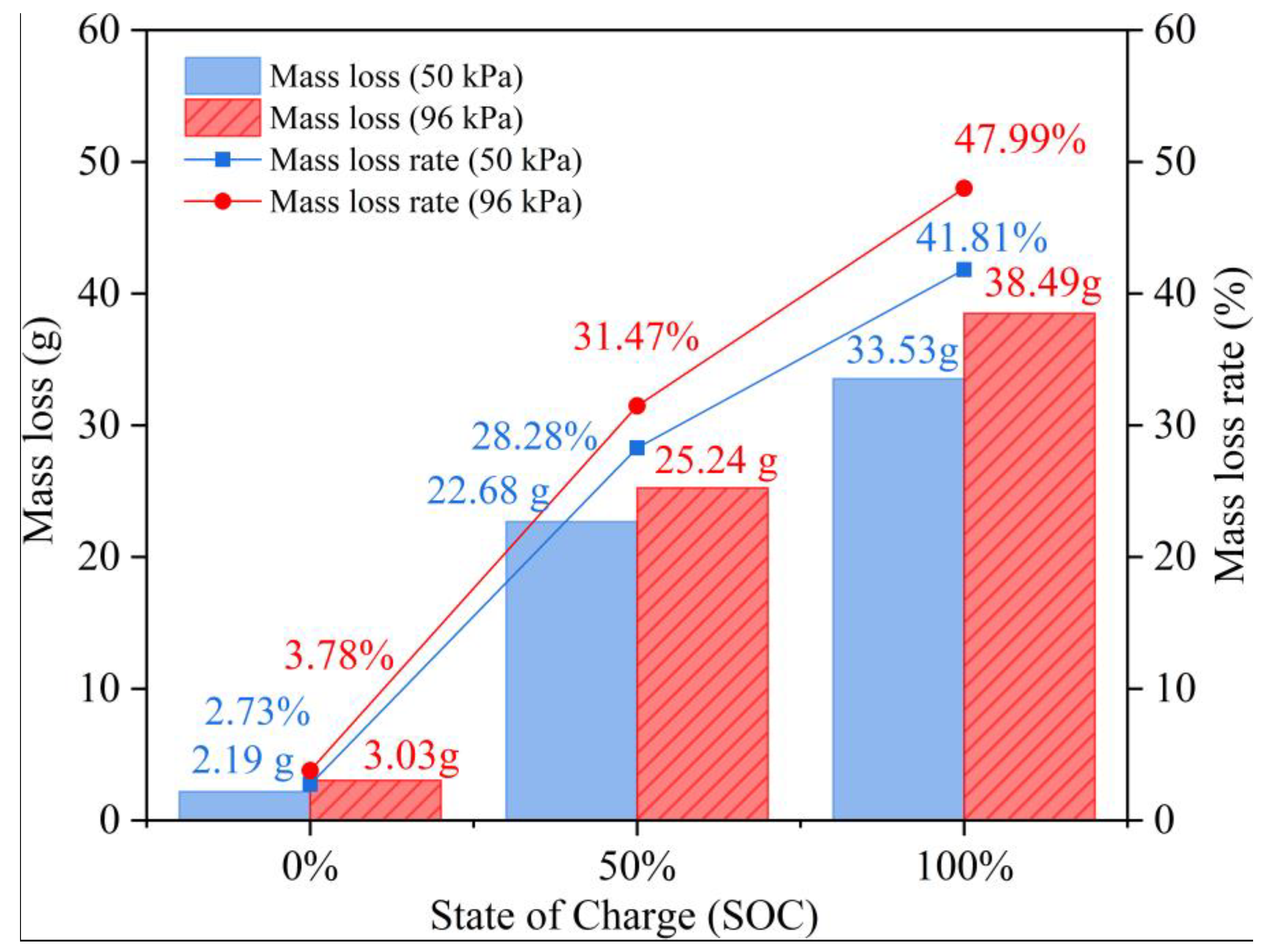
Furthermore, the quality change in the battery after thermal runaway was also measured and analyzed. As shown in Figure 3, with the increase in battery SOC from 0% to 100%, the mass loss and mass loss rate after thermal runaway increased significantly, and the ambient pressure environment further affected this trend. Specifically, when the SOC was 100%, the mass loss and mass loss rate reached 33.53 g and 41.92% at 50 kPa, while the mass loss and mass loss rate increased to 38.49 g and 48.12% at 96 kPa. This was attributed to the fact that more electric energy from the battery with high SOC was converted into heat energy, and the increase in ambient pressure also led to more substances participating in the thermal runaway reaction, which eventually enhanced the combustion intensity.

3.2. Characteristic Temperatures of Battery Thermal Runaway

3.2.1. Thermal Runaway Triggering Temperature

As can be seen from Table 2, for the same SOC, the thermal runaway triggering temperatures (TTR) increased with decreasing ambient pressure. When the ambient pressure decreased from 96 kPa to 50 kPa, the TTR increased from 108 °C to 143 °C at 100% SOC, and TTR increased from 104 °C to 129 °C at 50% SOC, indicating that the ambient pressure displayed a significant impact on the TTR. Under the same ambient pressure, the TTR decreased with decreasing SOC. When the SOC decreased from 100% SOC to 50% SOC, TTR decreased from 108 °C to 104 °C at 96 kPa, and TTR decreased from 114 °C to 107 °C at 70 kPa, indicating that the SOC had a significant impact on the TTR.
The battery case can be opened at a critical pressure difference between internal pressure (Pin) and ambient pressure (Pam). The venting of the electrolyte happened earlier when the battery was located in lower ambient pressure. More internal electrolytes were evaporated and volatilized after the battery case opened, and it erupted at a faster rate due to a higher pressure difference. The mass flow rate and volume flow rate of the electrolyte satisfied the following Equation (1) [22].
m = ρ V Δ P = P in P am
where m′ is the mass flow rate of the electrolyte, kg/s; V′ is the volume flow rate of the electrolyte, m3/s; ρ is the density of the electrolyte, kg/m3; ΔP is the pressure difference, Pa; Pin is the internal pressure of the battery, Pa; and Pam is the ambient pressure, Pa. The Equation (1) is a simplified form of the Continuity Equation, embodying the fundamental principle of “mass input equals mass output” in fluid dynamics. The battery case was prone to rupture at low air pressure compared with normal ambient pressure, which promoted the release of electrolytes at early stage of thermal runaway [23,24].
By combining Darcy’s law and Bernoulli’s law, the relationship between the volume flow rate and the pressure difference can be expressed as Equation (2) [22].
V = k d A μ Δ P Δ x Δ P   Darcy s   law 2 ρ e Δ P Δ P 1 2 Bernoulli s   law
where kd denotes the permeability, m2; μ denotes the dynamic viscosity, Pa·S; and Δx denotes the penetration distance. The volume flow rate increased with the increase in pressure difference. Under the lower-pressure environment, after the battery case was broken, the evaporation of electrolytes was accelerated, and the electrolytes participating in the exothermic reaction also decreased. At the same time, because the air flow at the rupture rapidly expanded to a level close to the ambient pressure, the accumulation of combustible gas and heat decreased, which led to the internal chemical reaction also decreasing accordingly. Therefore, the triggering time of thermal runaway was prolonged and the TTR was increased.
When the temperature rose to the TTR, the battery thermal runaway occurred. The internal chemical reactions mainly included the reaction between the electrolyte and lithium elements of the negative electrode, the reaction between the electrolyte and the oxygen decomposed from the positive electrode, as well as the decomposition reaction of the electrolyte itself. As the electrolyte was the main reactant for thermal runaway, the less the remaining amount of the electrolyte, the milder and weaker the internal reactions were, resulting in a higher temperature required to induce the battery into thermal runaway, and thus the higher the TTR. Thus, TTR was negatively correlated with the ambient pressure. That is, the lower the ambient pressure, the higher the value of TTR. The results in Table 2 and the above mechanism analysis mutually confirmed each other.

3.2.2. Effect of SOCs on Battery Thermal Runaway

During the charging process of the battery, the reaction of the negative electrode was interpreted as Equation (3).
L i + + e L i
The reaction occurring at the positive electrode was expressed as Equation (4).
L i ( N i 0.5 C o 0.3 M n 0.2 ) O 2 L i 1 x ( N i 0.5 C o 0.3 M n 0.2 ) O 2 + x  L i + + x  e
It can be seen from Equation (3) that, the higher the SOC, the higher the content of lithium in the negative electrode of the battery. Due to the high chemical activity of lithium, the higher lithium content in the battery leads to a more unstable state, making the battery more prone to thermal runaway.
The reaction for oxygen release from the positive electrode decomposition was shown as Equation (5).
L i ( N i 0.5 C o 0.3 M n 0.2 ) O 2 L i ( N i 0.5 C o 0.3 M n 0.2 ) O 2 y + y 2 O 2
The influence of SOC on battery thermal runaway is mainly reflected in two aspects. For one thing, as shown in Equation (3), the increase in SOC leads to an increase in lithium content in the negative electrode. Furthermore, Equation (4) shows that the cathode material is more likely to decompose and release oxygen when heated. In addition, Equation (5) shows that high SOC increases the proportion of Li1-x(Ni0.5Co0.3Mn0.2)O2 of cathode material, which has poor chemical stability and structural integrity compared with the original Li(Ni0.5Co0.3Mn0.2)O2. Therefore, under the condition of high SOC, the decomposition behavior of cathode materials of lithium-ion batteries is significantly intensified, accompanied by the release of oxygen. Because lithium metal has high chemical activity and strong reducibility, and oxygen is used as a combustion improver, they have a synergistic effect in the process of thermal runaway, which obviously accelerates the chain exothermic reaction. As shown in Table 3, with the increase in the SOC level, the reaction kinetics conditions in the battery changed, which led to the acceleration of the heat generation rate and the decrease in the thermal runaway peak temperatures, which significantly promoted the development of thermal runaway behavior.

3.2.3. Influence of Ambient Pressure on the Thermal Runaway Peak Temperatures

The influence of ambient pressure on thermal runaway peak temperatures (Tpeak) is analyzed below. The low ambient pressure environment mainly affects Tpeak by changing the chemical reaction of the battery [12]. Specifically, the low-pressure environment affected the thermal runaway process by regulating the distribution of combustible materials. That is, the reduction in pressure reduced the internal electrolytic quality. As the main reactant of thermal runaway, the quality of the residual electrolyte directly affected the reaction intensity. The more residual, the more fully the reaction lasted, leading to a higher peak temperature Tpeak of the battery. At the same time, the increase in external electrolysis strengthened the heat transfer to the environment and increased the peak temperature.
As shown in Table 3, under the same SOC, the thermal runaway peak temperature of lithium-ion batteries showed a significant downward trend with the decrease in ambient pressure. When the SOC was 100%, the ambient pressure dropped from 96 kPa to 50 kPa, and its peak temperature reduced from 805 °C to 784 °C and 718 °C. When the SOC was 50%, the peak temperature gradually decreased from 773 °C to 723 °C and 650 °C. Even for the 0% SOC group, the peak temperature decreased from 360 °C (96 kPa) to 202 °C (50 kPa) with the decrease in ambient pressure. The above phenomenon can be attributed to the decrease in oxygen partial pressure significantly inhibiting the combustion reaction of the electrolyte and electrode active materials and reducing the reaction intensity in the process of thermal runaway. Therefore, the reduction in environmental pressure effectively suppressed the severity of thermal runaway in lithium-ion batteries.

3.3. Effect of Pressure Environments on Battery Thermal Runaway Behavior

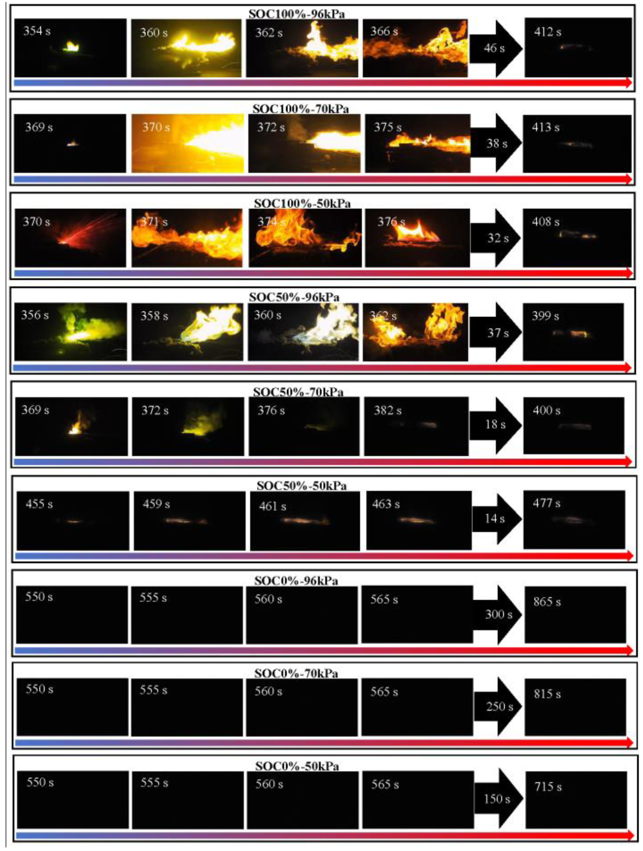
As shown in Figure 4, through observation and analysis of the thermal runaway behavior of batteries under different environmental pressures, it was found that their thermal runaway behavior follows similar patterns and can be divided into six stages.
I.
Initial stage. Preliminary heating of the battery happened.
II.
Deformation stage. At this stage, partial irreversible pyrolysis reactions occurred inside the battery, generating large amounts of flammable gas [25]. Combined with the physical vaporization of the electrolyte solvent, internal pressure caused visible deformation of the battery. However, the aluminum laminate film had not yet ruptured, and no large-scale internal short circuit occurred.
III.
Jet stage. It was observed that, after the local rupture of aluminum-laminated film, a small amount of smoke was first released, and then sparks were ejected, which led to significant jet behavior. The trigger time of the eruption was negatively correlated with the ambient pressure. The trigger time was 370 s at 100%SOC-50kPa, which was 16 s and 85 s later than those at 50%SOC-96kPa and 50%SOC-50kPa, respectively. Furthermore, the position of the erupt port was random, which made it difficult to predict the flame injection direction. This phenomenon was influenced by many factors, including the geometry of the battery, the location of aluminum film packaging, and the fixing way of battery and heater. In this experiment, the erupt ports mainly appeared on the nearby side of battery tab.
IV.
Combustion and explosion stage. As a pressure relief point, the nozzle caused violent combustion and explosion. At this time, the heat production rate of the battery was significantly higher than the heat dissipation capacity, and it reached the critical state of thermal runaway under the action of thermal accumulation and pressure difference. The low ambient pressure delayed the trigger time of combustion and explosion. The explosion intensity of 50%SOC-50kPa was obviously weaker than the other five experiments. Notably, the batteries for SOC0%-96kPa, SOC0%-70kPa, and SOC0%-50kPa scenes did not undergo thermal runaway throughout the entire process, so the full video recording displayed as a black screen. This indicated that, in the fully discharged state, even the low-pressure environment would not trigger the risk of thermal runaway.
V.
Injection fire stage. Combustible mixed gas formed by vaporization of the electrolyte continued to burn.
VI.
Attenuation stage. Energy release was depleted, the thermal runaway process concluded, and the battery suffered irreversible damage overall.
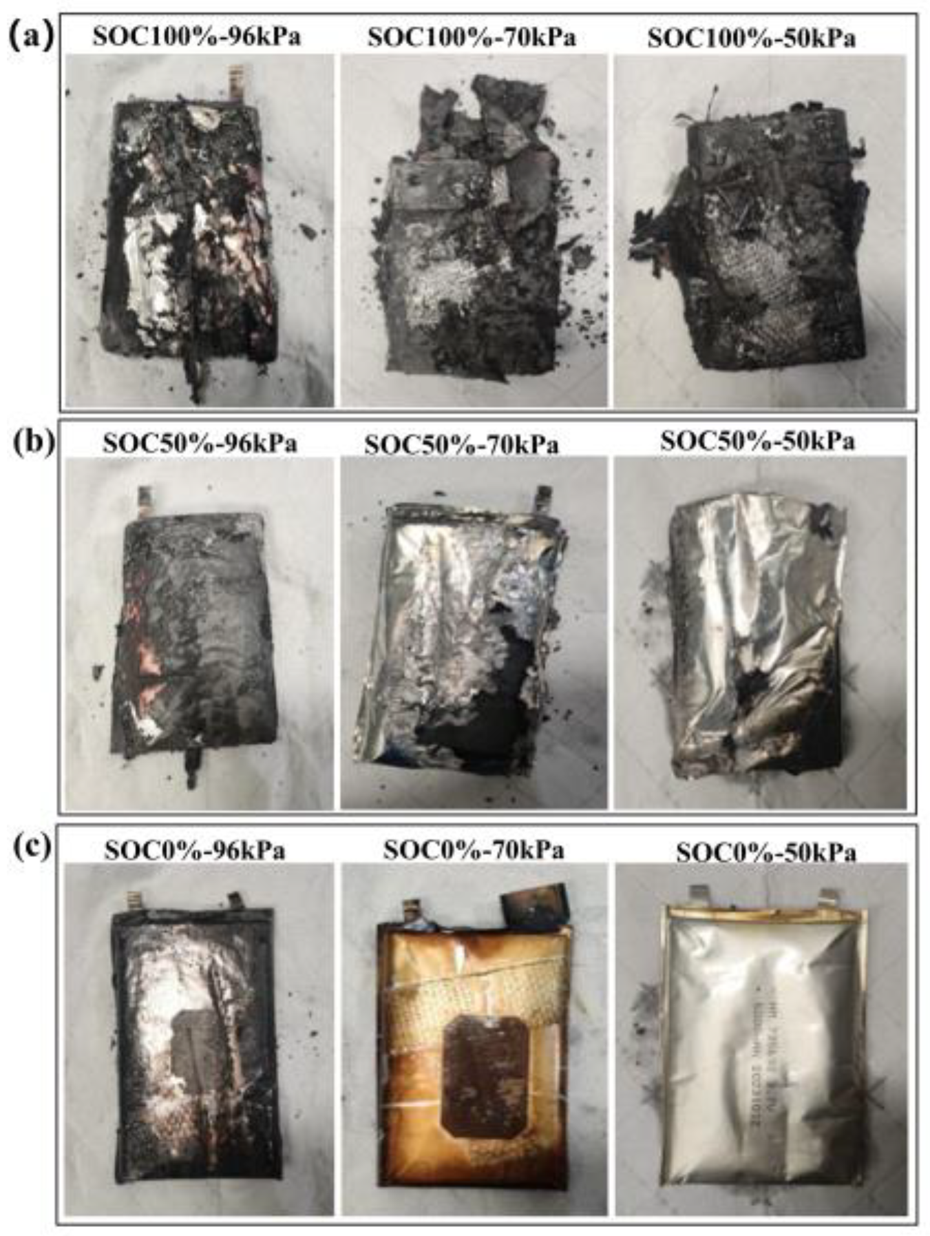
As shown in Figure 5, the thermal runaway combustion behavior of the battery was significantly different under different pressures. The experimental results showed that, under the conditions of 100% SOC and 50% SOC, the battery was obviously burned and eventually destroyed. Especially under the condition of 100% SOC, the battery shell was completely burned, and the internal structure was seriously deformed. In contrast, the damage degree of 50% SOC was relatively slight. It was worth noting that the battery with 0% SOC only showed minimal combustion damage, the external packaging remained basically intact and there was no obvious damage, and all the samples tested with 0% SOC were accompanied by significant expansion. These phenomena showed that SOC level displayed a decisive influence on the severity of battery thermal runaway.

3.4. Analysis of Residues After Battery Thermal Runaway

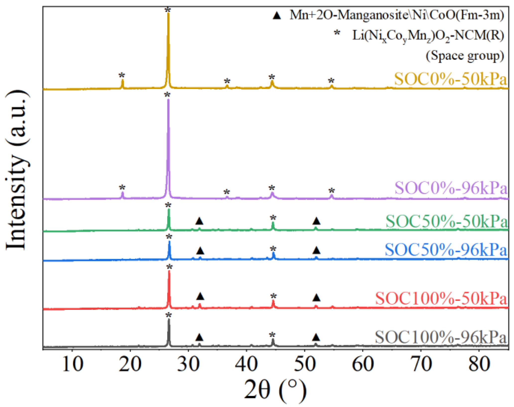
X-ray diffraction (XRD) was used to analyze the residue of the lithium-ion battery after thermal runaway. As shown in Figure 6, it revealed the structural evolution law of the material. The original Li(Ni0.5Co0.3Mn0.2)O2 cathode material presented a typical R-3m space group layered structure. However, after thermal runaway, the material was transformed into three phases, including MnO, Ni, and CoO. This transition was due to the oxidation reactions during heating process, such as from Ni2+ to Ni3+/Ni4+, and from Co3+ to Co4+. The battery with 0% SOC still maintained its structural integrity at 200 °C due to its low degree of lithium removal and low content of high valence ions. The batteries with 50% SOC and 100% SOC continued to burn once thermal runaway was triggered due to the existence of high active components. However, the final composition of batteries after thermal runaway showed good consistency [26].
There were significant differences in the thermal stability of battery materials under different SOCs. In the 50% SOC battery, only a small amount of M3O4 spinel phase was transformed into rock salt structure. However, CoO in the 100% SOC battery showed obvious thermal instability, and it was easy to decompose and participate in the reaction when heated. The reduction of Ni4+ to low valent nickel was bound to be accompanied by the release of cathode oxygen [27]. For high ambient pressure, the reactive oxygen species reacted violently with the electrolyte, which was due to the key factor causing serious thermal runaway [28]. Because SOC level was positively correlated with oxygen release, SOCs determined the critical condition and severity of thermal runaway.
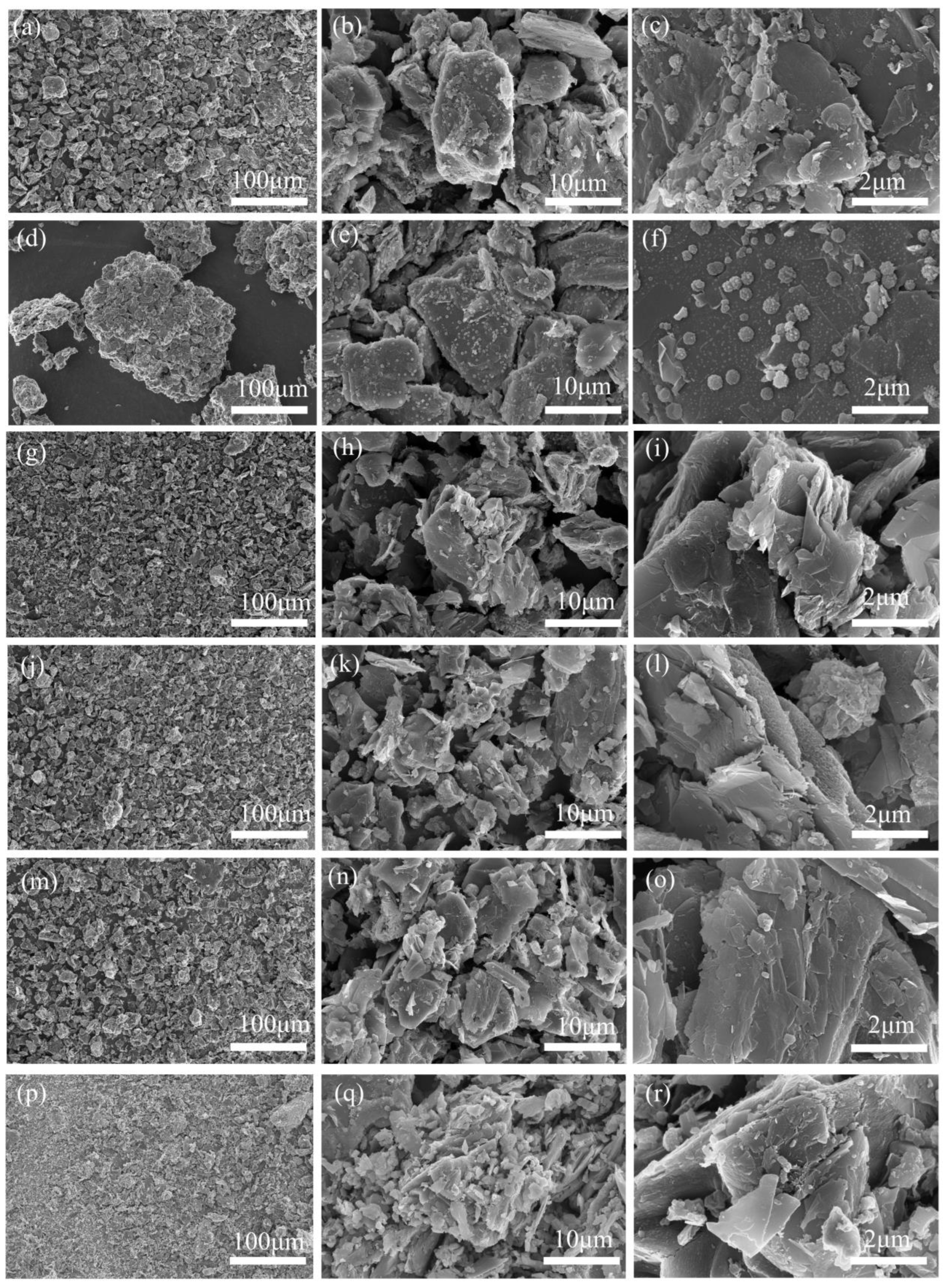
The morphology of residue after battery thermal runaway was investigated by SEM (Scanning Electron Microscope). Figure 7 reveals the structural evolution characteristics at different SOCs. Under the condition of 0% SOC, even when heated to 200 °C, the microstructure of the electrode material remained intact, the particle profile was clear, and the morphology was full, which was attributed to the relatively good thermal stability. In contrast, the batteries with 50% SOC and 100% SOC showed significant structural degradation. The electrode material was completely melted, the original spherical structure was completely destroyed, and the surface presented a serious melting morphology. This difference clearly showed that the degree of electrode materials participating in the thermal runaway reaction was significantly intensified with the increase in SOC. The structural damage of the 100% SOC battery was the most serious, which proved the severity of the thermal runaway reaction at high SOCs. These morphological characteristics were mutually confirmed with the XRD results.
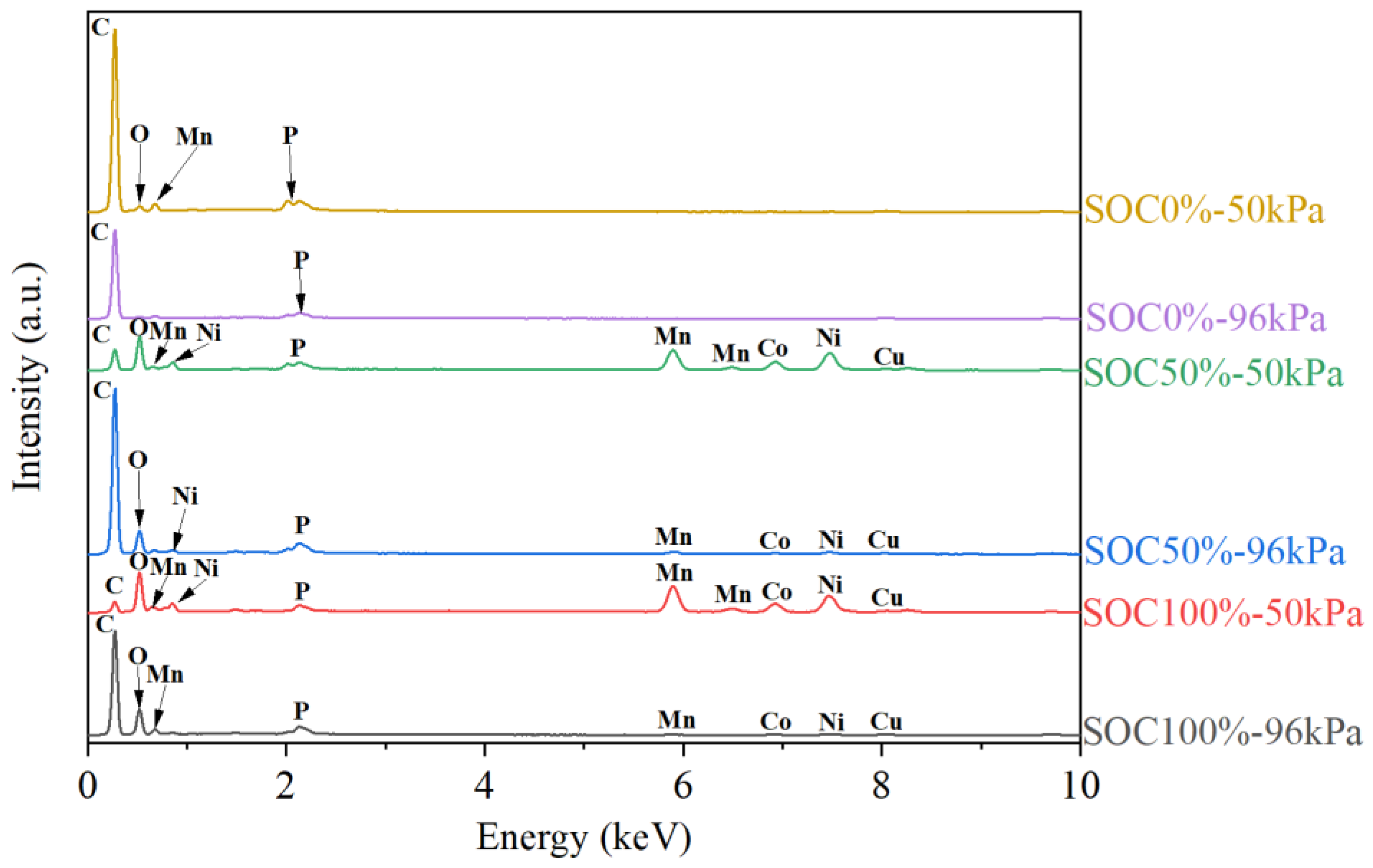
Figure 8 shows the EDS spectra of residues after battery thermal runaway at different conditions. A significant Cu signal was detected at all conditions, and its characteristic peak in the low energy region indicated that the copper foil current collector had completely melted. The Cu peak intensity of the 100% SOC sample was the highest, which proved that the increase in SOC aggravated the severity of thermal runaway. The detection of cathode active material elements (Ni, Co, Mn) confirmed that the cathode material was deeply involved in the thermal runaway reaction, and the L pedigree line detected in the low energy region (<1 keV) indicated that there was a high concentration of molten metal mixture in the residue. With the increase in SOC, the relative intensity of the metal peak decreased, which was attributed to the deep reduction of cathode materials into a metal simple substance or alloy, and some metals could be volatilized and evaporated. The appearance of the P element confirmed the violent decomposition of the LiPF6 electrolyte, and its peak intensity was more significant under the low SOC state, which was due to the increase in volatile phosphorus-containing products at high SOCs, while low SOC was more conducive to the retention of solid phosphide. The distribution characteristics of C and O elements showed that the intense combustion reaction at high SOC helped to transform organic combustible substances into more combustion products, while more residues remained in the samples with low SOCs.
Furthermore, the percentage content of each element in the EDS analysis of residues after battery thermal runaway is displayed in Table 4. It was found that the trace amounts of Al and Cu detected in the residue were derived from the current collector materials, while F and P were derived from the electrolyte. Under the condition of 0% SOC, the carbon content was as high as about 90 at%, while the contents of Ni, Co, and Mn were not higher than 0.5 at%, which indicated that the thermal runaway reaction almost did not occur. When SOC rose to 50%, the content of C decreased to 50.27 at% at low pressure (50 kPa), while the percentage contents of Ni (9.87 at%), Co (4.02 at%), and Mn (6.47 at%) increased obviously. Under normal pressure (96 kPa), the content of C rose to 79.93 At%, while the contents of Mn (0.40 at%), Co (0.24 at%), and Ni (0.58 at%) decreased obviously. Under the condition of 100%SOC-50kPa, the contents of Mn (10.99 at%), Co (5.34 at%), and Ni (12.19 at%) were very high, which indicated that the low-pressure environment significantly promoted the decomposition reaction of cathode materials at high SOC batteries.

3.5. Mechanism Analysis of Influence of Ambient Pressure and SOCs on Battery Thermal Runaway

The battery thermal runaway behavior at different SOCs was systematically analyzed. The SOC level was positively correlated with the severity of thermal runaway. Under the condition of low SOC (0%), the battery showed an obscure thermal runaway process. XRD and SEM analysis showed that its internal structure remained intact and the electrode material was only slightly deformed. With the increase in SOC (50–100%), the diaphragm was gradually damaged, resulting in direct contact between anode and cathode. SEM observation showed that the electrode materials were obviously melted, and XRD detected a large number of reduction phase products. This structural degradation reflected the exothermic reaction inside the battery. With the increase in SOC, the thermal runaway intensity and heat release of the battery were also increased. This study provides an important basis for understanding the influence of SOCs on battery safety.

4. Conclusions

In this study, the battery thermal runaway characteristics at different SOCs and ambient pressures were systematically explored. When the ambient pressure was reduced, the trigger time and trigger temperature of thermal runaway increased to some extent, while the peak temperature of thermal runaway decreased significantly. The 100% SOC battery showed a complete melting, while the 0% SOC battery kept its structural integrity. The unstable Ni and CoO at high SOCs catalyzed the chain reaction. The pressure and SOC coupling effect was remarkable; the peak temperature of the highest-risk combination (96 kPa + 100% SOC) was greater than 800 °C, while the peak temperature of the lowest-risk combination (50 kPa + 0% SOC) was less than 360 °C. Low pressure delayed thermal runaway response, and the combustion intensity was still weak.
In aviation transportation applications, when the state of charge is less than 50%, the risk and severity of battery thermal runaway are significantly reduced, which reduces the difficulty of prevention and control of thermal runaway and improves the safety of transportation. Meanwhile, real-time monitoring and early warning mechanisms should be established to gain critical time for implementing emergency measures, and it is also necessary to comprehensively evaluate its impact on logistics efficiency and cost. Based on these findings, it is suggested that the SOC in aviation transportation should not exceed 50%, and the thermal insulation design and fire resistance of the battery packaging box should be strengthened. This provides an important experimental basis for battery safety in aviation transportation environments.

Author Contributions

Conceptualization, M.Z. (Maoyong Zhi) and H.C.; methodology, M.Z. (Maoyong Zhi) and H.C.; software, H.C.; validation, H.C. and M.Z. (Mingge Zhang); formal analysis, M.Z. (Mingge Zhang); investigation, H.C. and M.Z. (Maoyong Zhi); resources, M.Z. (Maoyong Zhi); data curation, K.Z.; writing—original draft preparation, M.Z. (Maoyong Zhi) and H.C.; writing—review and editing, M.Z. (Maoyong Zhi), and Q.S.; visualization, H.C.; supervision, M.Z. (Maoyong Zhi) and Q.S.; project administration, M.Z. (Maoyong Zhi); funding acqui-sition, M.Z. (Maoyong Zhi). All authors have read and agreed to the published version of the manuscript.

Funding

This work was financially supported by Civil Aviation Safety Capacity Building Project of China (NO: MHAQ2024035), Sichuan Science and Technology Program (NO: 2025YFHZ0037), Fundamental Research Funds for the Central Universities (NO: 24CAFUC01008).

Data Availability Statement

The data presented in this study are available on request from the corresponding author.

Conflicts of Interest

The authors declare no conflicts of interest.

References

  1. Ouyang, D.; Liu, B.; Huang, J.; Wang, Z. Degradation and safety performance of lithium-ion cells under high-rate charging/discharging scenarios. Process Saf. Environ. Prot. 2024, 185, 76–85. [Google Scholar] [CrossRef]
  2. Urquizo, J.; Singh, P. A review of health estimation methods for Lithium-ion batteries in Electric Vehicles and their relevance for Battery Energy Storage Systems. J. Energy Storage 2023, 73, 109194. [Google Scholar] [CrossRef]
  3. Mo, C.; Xie, J.; Zhang, G.; Zou, Z.; Yang, X. All-climate battery thermal management system integrating units-assembled phase change material module with forced air convection. Energy 2024, 294, 130642. [Google Scholar] [CrossRef]
  4. Jin, Y.; Zhao, Z.; Miao, S.; Wang, Q.; Sun, L.; Lu, H. Explosion hazards study of grid-scale lithium-ion battery energy storage station. J. Energy Storage 2021, 42, 102987. [Google Scholar] [CrossRef]
  5. Feng, X.; Ren, D.; He, X.; Ouyang, M. Mitigating thermal runaway of lithium-ion batteries. Joule 2020, 4, 743–770. [Google Scholar] [CrossRef]
  6. Wang, Y.; Feng, X.; Huang, W.; He, X.; Wang, L.; Ouyang, M. Challenges and opportunities to mitigate the catastrophic thermal runaway of high-energy batteries. Adv. Energy Mater. 2023, 13, 2203841. [Google Scholar] [CrossRef]
  7. Zhi, M.; Fan, R.; Zheng, L.; Yue, S.; Pan, Z.; Sun, Q.; Liu, Q. Experimental investigation on hydrated salt phase change material for lithium-ion battery thermal management and thermal runaway mitigation. Energy 2024, 307, 132685. [Google Scholar] [CrossRef]
  8. Qin, P.; Sun, J.; Wang, Q. A new method to explore thermal and venting behavior of lithium-ion battery thermal runaway. J. Power Sources 2021, 486, 229357. [Google Scholar] [CrossRef]
  9. Zhao, C.; Sun, J.; Wang, Q. Thermal runaway hazards investigation on 18650 lithium-ion battery using extended volume accelerating rate calorimeter. J. Energy Storage 2020, 28, 101232. [Google Scholar] [CrossRef]
  10. Jindal, P.; Bhattacharya, J. Understanding the thermal runaway behavior of Li-ion batteries through experimental techniques. J. Electrochem. Soc. 2019, 166, A2165. [Google Scholar] [CrossRef]
  11. Chen, M.; Ouyang, D.; Weng, J.; Liu, J.; Wang, J. Environmental pressure effects on thermal runaway and fire behaviors of lithium-ion battery with different cathodes and state of charge. Process Saf. Environ. Prot. 2019, 130, 250–256. [Google Scholar] [CrossRef]
  12. Meng, D.; Weng, J.; Wang, J. Experimental Investigation on Thermal Runaway of Lithium-Ion Batteries under Low Pressure and Low Temperature. Batteries 2024, 10, 243. [Google Scholar] [CrossRef]
  13. Sun, Q.; Liu, H.; Zhi, M.; Zhao, C.; Jia, J.; Lv, P.; Xie, S.; Chen, X. Lithium-ion battery thermal runaway propagation characteristics under 20 kPa with different airflow rates. Fire Technol. 2023, 59, 1157–1179. [Google Scholar] [CrossRef]
  14. Liu, Q.; Yi, X.; Han, X. Effect of different arrangement on thermal runaway characteristics of 18650 lithium ion batteries under the typical pressure in civil aviation transportation. Fire Technol. 2020, 56, 2509–2523. [Google Scholar] [CrossRef]
  15. Fu, Y.; Lu, S.; Shi, L.; Cheng, X.; Zhang, H. Ignition and combustion characteristics of lithium ion batteries under low atmospheric pressure. Energy 2018, 161, 38–45. [Google Scholar] [CrossRef]
  16. Wang, H.; Du, Z.; Liu, L.; Zhang, Z.; Hao, J.; Wang, Q.; Wang, S. Study on the thermal runaway and its propagation of lithium-ion batteries under low pressure. Fire Technol. 2020, 56, 2427–2440. [Google Scholar] [CrossRef]
  17. Jia, Z.; Huang, Z.; Zhai, H.; Qin, P.; Zhang, Y.; Li, Y.; Wang, Q. Experimental investigation on thermal runaway propagation of 18,650 lithium-ion battery modules with two cathode materials at low pressure. Energy 2022, 251, 123925. [Google Scholar] [CrossRef]
  18. Chen, X.; Zhang, X.; Wang, H.; Jia, J.; Xie, S.; Zhi, M.; Fu, J.; Sun, Q. Influence of ambient pressure and heating power on the thermal runaway features of lithium-ion battery. J. Electrochem. Energy Convers. Storage 2021, 18, 021014. [Google Scholar] [CrossRef]
  19. He, Y.; Zhang, L.; Zhang, D.; Wang, Z.; Liu, Y. Experimental and Computational Analyses of Thermal Runaway Behavior of Lithium Ion Pouch Battery at Low Ambient Pressure. J. Electrochem. Energy Convers. Storage 2023, 20, 041007. [Google Scholar] [CrossRef]
  20. Sun, Q.; Liu, H.; Zhi, M.; Chen, X.; Lv, P.; He, Y. Thermal characteristics of thermal runaway for pouch lithium-ion battery with different state of charges under various ambient pressures. J. Power Sources 2022, 527, 231175. [Google Scholar] [CrossRef]
  21. Liu, Y.; Niu, H.; Xu, C.; Huang, X. Thermal runaway propagation in linear battery module under low atmospheric pressure. Appl. Therm. Eng. 2022, 216, 119086. [Google Scholar] [CrossRef]
  22. Liu, Y.; Niu, H.; Li, Z.; Liu, J.; Xu, C.; Huang, X. Thermal runaway characteristics and failure criticality of massive ternary Li-ion battery piles in low-pressure storage and transport. Process Saf. Environ. Prot. 2021, 155, 486–497. [Google Scholar] [CrossRef]
  23. Wang, Y.; Wang, Y.; Zhao, J.; Li, H.; Xu, C.; Li, Y.; Wang, H.; Lu, L.; Dai, F.; Yu, R.; et al. Experimental Research on Thermal-Venting Characteristics of the Failure 280 Ah LiFePO4 Battery: Atmospheric Pressure Impacts and Safety Assessment. Batteries 2024, 10, 270. [Google Scholar] [CrossRef]
  24. Wang, Z.; Song, Y.; Yin, B.; Shi, B.; Li, Z.; Yu, J. Effect of ambient pressure on the fire characteristics of lithium-ion battery energy storage container. J. Loss Prev. Process Ind. 2024, 92, 105459. [Google Scholar] [CrossRef]
  25. Liu, C.; Dai, H.; Wang, D.; Ren, X.; Lyu, S.; Fan, J.; Lv, S.; Zhu, S.; Li, N.; Wang, Y. Understanding Thermal Runaway in Lithium-Ion Batteries: Trigger, Mechanism, and Early Warning Strategies. J. Electrochem. Soc. 2024, 171, 120527. [Google Scholar] [CrossRef]
  26. Elsner, F.; Gerhards, P.; Berrier, G.; Vincent, R.; Dubourg, S.; Pischinger, S. Detailed Characterization of Thermal Runaway Particle Emissions from a Prismatic NMC622 Lithium-Ion Battery. Batteries 2025, 11, 225. [Google Scholar] [CrossRef]
  27. Ju, X.; Hou, X.; Liu, Z.; Du, L.; Zhang, L.; Xie, T.; Paillard, E.; Wang, T.; Winter, M.; Li, J. Revealing the Effect of High Ni Content in Li-Rich Cathode Materials: Mitigating Voltage Decay or Increasing Intrinsic Reactivity. Small 2023, 19, 2207328. [Google Scholar] [CrossRef] [PubMed]
  28. Tian, X.; Yi, Y.; Fang, B.; Yang, P.; Wang, T.; Liu, P.; Qu, L.; Li, M.; Zhang, S. Design strategies of safe electrolytes for preventing thermal runaway in lithium ion batteries. Chem. Mater. 2020, 32, 9821–9848. [Google Scholar] [CrossRef]
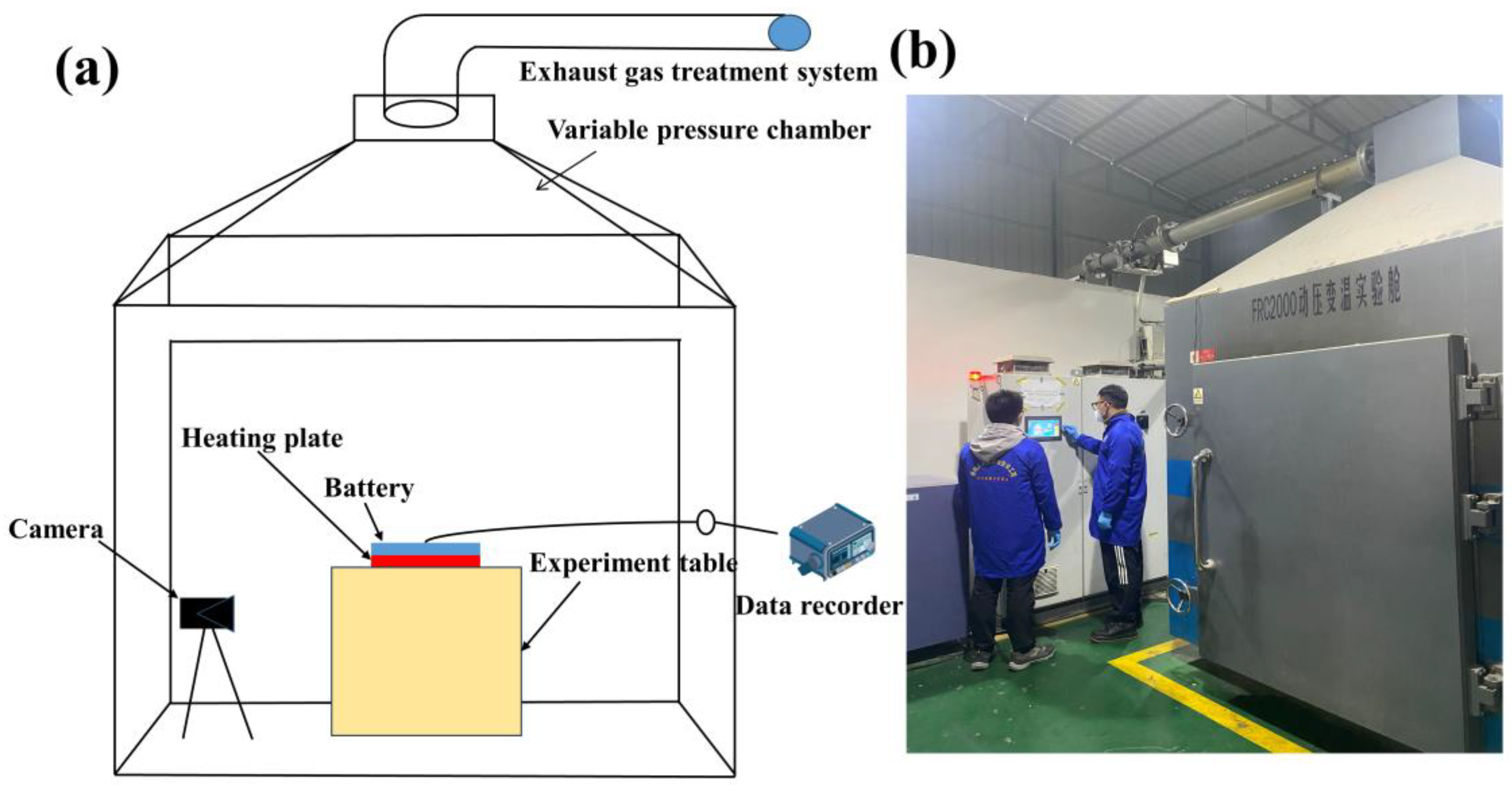
Figure 1. (a) Schematic diagram, and (b) physical diagram of battery thermal runaway experiments.
Batteries 11 00339 g001
Figure 2. Thermal runaway temperature curves for three SOCs, (a) 100% SOC, (b) 50% SOC, (c) 0% SOC, under different ambient pressures.
Batteries 11 00339 g002
Figure 3. Battery mass loss and mass loss rate as a function of SOC.
Batteries 11 00339 g003
Figure 4. Digital photos of thermal runaway under three SOCs (100% SOC, 50% SOC, 0% SOC) and three ambient pressures (96 kPa, 70 kPa, 50 kPa).
Batteries 11 00339 g004
Figure 5. Digital photos of battery after thermal runaway under at three SOCs (SOC 100%, SOC 50%, SOC 0%) and different ambient pressures (96 kPa, 70 kPa, 50 kPa).
Batteries 11 00339 g005
Figure 6. XRD patterns of residues for battery thermal runaway with different SOCs and ambient pressures.
Batteries 11 00339 g006
Figure 7. SEM images of batteries residues after thermal runaway: (ac) 0%SOC-50kPa; (df) 0%SOC-96kPa; (gi) 50%SOC-50kPa; (jl) 50%SOC-96kPa; (mo) 100%SOC-50kPa; (pr) 100%SOC-96kPa.
Batteries 11 00339 g007
Figure 8. EDS spectra of residues after battery thermal runaway.
Batteries 11 00339 g008
Table 1. Technical specifications of pouch ternary lithium-ion battery.
ParameterValue
Size (length × width × height)115 mm × 65 mm × 4 mm
Weight (g)80.20
Cathode materialLi(Ni0.5Co0.3Mn0.2)O2
Anode materialGraphite
Nominal capacity (mAh)5000
Nominal voltage (V)3.7
Charge cutoff voltage (V)4.25
Discharge cutoff voltage (V)2.7
Table 2. Thermal runaway triggering temperatures under different operating conditions.
ScenesTTR/°CScenesTTR/°C
100%SOC-96kPa10850%SOC-96kPa104
100%SOC-70kPa11450%SOC-70kPa107
100%SOC-50kPa14350%SOC-50kPa129
Table 4. EDS test result of residues after battery thermal runaway.
ScenesElemental Amounts (at%)
COAlCuPFNiCoMn
0%SOC-50kPa89.875.160.010.390.483.980.040.020.05
0%SOC-96kPa92.094.090.020.490.173.080.010.020.03
50%SOC-50kPa50.2725.180.171.030.552.449.874.026.47
50%SOC-96kPa79.9316.640.100.360.021.730.580.240.40
100%SOC-50kPa33.7931.140.651.110.004.7912.195.3410.99
100%SOC-96kPa71.9722.740.190.370.004.080.400.140.11
Table 3. Thermal runaway peak temperatures under different conditions.
ScenesTpeak/°CScenesTpeak/°CScenesTpeak/°C
100%SOC-96kPa80550%SOC-96kPa7730%SOC-96kPa360
100%SOC-70kPa78450%SOC-70kPa7230%SOC-70kPa271
100%SOC-50kPa71850%SOC-50kPa6500%SOC-50kPa202
Disclaimer/Publisher’s Note: The statements, opinions and data contained in all publications are solely those of the individual author(s) and contributor(s) and not of MDPI and/or the editor(s). MDPI and/or the editor(s) disclaim responsibility for any injury to people or property resulting from any ideas, methods, instructions or products referred to in the content.