Article

Incremental Capacity-Based Variable Capacitor Battery Model for Effective Description of Charge and Discharge Behavior †

Department of Electrical, Electronic and Computer Engineering, University of Ulsan, Ulsan 44610, Republic of Korea
*
Author to whom correspondence should be addressed.
This paper is an extended version of the conference paper, Ngoc-Thao Pham, Jong-Hoon Kim, and Sung-Jin Choi, “Novel Battery Model Employing Variable Capacitor for Effective Description of SOC Behavior”, which was presented in the 2024 IEEE Applied Power Electronics Conference and Exposition (APEC) held in Long Beach, CA, USA, 25–29 February 2024.
Batteries 2025, 11(8), 300; https://doi.org/10.3390/batteries11080300
Submission received: 30 June 2025 / Revised: 29 July 2025 / Accepted: 2 August 2025 / Published: 5 August 2025
(This article belongs to the Special Issue Batteries: 10th Anniversary)

Abstract

Determining charge and discharge behavior is essential for optimizing charging strategies and evaluating balancing algorithms in battery energy storage systems and electric vehicles. Conventionally, a sequence of circuit simulations or tedious hardware tests is required to evaluate the performance of the balancing algorithm. To mitigate these problems, this paper proposes a variable capacitor model that can be easily built from the incremental capacity curve. This model provides a direct and insightful R-C time constant method for the charge/discharge time calculation. After validating the model accuracy by experimental results based on the cylindrical lithium-ion cell test, a switched-capacitor active balancing and a passive cell balancing circuit are implemented to further verify the effectiveness of the proposed model in calculating the cell balancing time within 2% error.

1. Introduction

Due to the rapid evolution of battery energy storage systems (BESS) and electric vehicles (EVs), the demand for high-capacity batteries has significantly increased. Depending on application requirements, multiple cells are connected in series and/or parallel to meet power and energy requirements [1,2,3]. However, their utilization comes with a set of challenges in ensuring the longevity and safety of these systems [4,5,6], and thus battery management systems (BMS) must implement effective charging strategies and cell balancing algorithms [7,8,9].
One of the most critical factors in both the charging control and balancing operation of batteries is accurate calculation of the charge/discharge time (CDT) [10,11,12]. In conventional practice, evaluating the performance of cell-balancing algorithms has been a challenging task. Typically, this process involves a sequence of circuit simulations or hardware tests [13,14,15]. While effective, these approaches are often time-consuming, resource-intensive, and not well suited for systems with large battery capacities. The scale and complexity of these systems necessitate an alternative approach that can provide direct and accurate calculations of the balancing time. Likewise, in multi-stage constant current charging algorithms [16,17], CDT approximation allows determining the stage duration for various constant currents, energy distributions, and thermal behaviors. However, determining CDT is particularly challenging due to the non-linear and time-varying nature of battery behavior, especially under aging conditions.
Accurate modeling of battery behavior is essential for addressing these issues. Among the various modeling techniques available [18,19], equivalent circuit models (ECMs) have gained prominence in real-time applications due to their low computational complexity and straightforward model parameter extraction [20,21]. Conventional ECMs, such as the Randles model consisting of a variable voltage source and a resistor-capacitor (RC) network, are widely adopted (Figure 1). However, a drawback of the voltage source-based model is that the voltage source does not dynamically interact with the circuit without an external feedback mechanism, such as the state of charge (SOC) calculation (Figure 2a). Therefore, these models are often insufficient for predicting dynamic behaviors like CDT or balancing time without detailed time-domain simulations.
In contrast, the capacitor-based battery model [22], as Figure 2b, is more circuit-friendly. Because capacitors naturally respond to changes in voltage, they provide a dynamic interaction with the circuit during charge and discharge processes, even without external SOC feedback. This characteristic enables analytical and effective CDT determination based on circuit parameters and voltage conditions. Figure 3 illustrates the existing capacitor-based battery models. Figure 3a presents a simple RC model that assumes constant capacitance Cb and resistance Rb [23]. While this approach offers ease of implementation for charging time calculation, it does not provide details for an accurate description of non-linear behaviors. In [24], the author introduced a more detailed resistance–capacitance battery model based on SOC and temperature as Figure 3b. While this model enhances the model accuracy, it increases system complexity. Likewise, a non-linear double-capacitor model (Figure 3c) is proposed in [25]. The capacitor C s integrates the current to set the SOC information to adjust the voltage source, allowing the battery dynamics to be captured, but it introduces additional complexity that limits its practical use in control algorithms and embedded systems.
To ensure the simplicity of the model and describe the battery non-linearity, this paper introduces an effective modeling approach that replaces the voltage-source structure with a variable capacitance model. This model is inspired by incremental capacity (IC) analysis [26,27,28,29], a technique that reveals the capacity fading and impedance increment of lithium-ion batteries by differentiating capacity with respect to voltage (dQ/dV). The IC profile directly reflects how the battery charge storage capacity varies with voltage, providing physically meaningful and electrochemically relevant information for modeling. Moreover, the IC curve is highly sensitive to aging phenomena, allowing the model to be easily updated with new IC data to reflect battery degradation. By leveraging the IC curve, the proposed model allows direct calculation of CDT using the R-C time constant method that is well established in circuit theory, offering a practical and computationally efficient method for predicting CDT. The contributions of this work are summarized as follows:
  • A voltage-dependent capacitor battery model is proposed, which is directly obtained from the IC curve.
  • Equivalent capacitance is introduced to approximately calculate the balancing time process, together with the circuit equivalent resistance.
  • A balancing time calculation process is formulated for active balancing topologies as well as a passive balancing circuit.
The rest of the paper is organized as follows: Section 2 presents the derivation and formulation of the variable capacitor model. Section 3 discusses its application in balancing time calculation and integration with the balancing scheme. Finally, the conclusions are presented in Section 4.

2. IC-Based Variable Capacitor Battery Model

2.1. Model Formulation

The proposed model utilizes the relationship between the stored charge and the open circuit voltage (OCV) of the battery to determine the incremental capacitance. It adopts a simple structure consisting of a variable capacitor in series with the RC, as shown in Figure 4, where the capacitance changes depending on the OCV. The key idea is to replace the conventional variable voltage source in the Randles model with a variable capacitor. This variable capacitor can be combined with various battery models, depending on the specific application requirements.
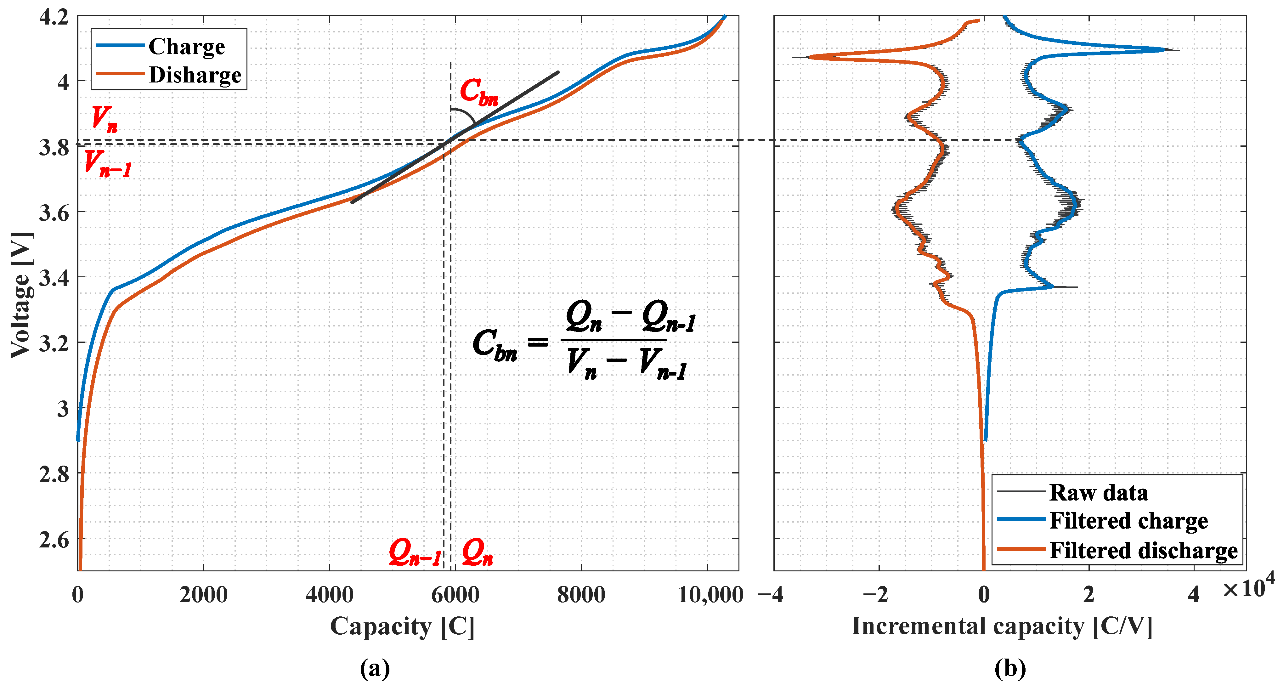
To construct the proposed model, the capacitance at each OCV point is obtained by calculating the tangential slope of the capacity vs. the OCV ( Q V O C ) curve, as illustrated in Figure 5a. As a result, the capacitance function is defined by
C b ( V O C ) = d Q ( V O C ) d V O C
This derivative corresponds to IC, a diagnostic profile for assessing lithium-ion battery aging and internal characteristics, as shown in Figure 5b. Therefore, the IC curve can be directly utilized as the capacitance function in the proposed model.
In this work, the IC curve is extracted from experimental data by conducting a constant current (CC) charge and discharge test at low current, typically C / 20 , to ensure that the terminal voltage closely approximates the true OCV. During this process, the battery voltage and corresponding cumulative capacity are recorded. The data are then uniformly resampled with a fixed voltage interval, commonly set to 1 mV, to compute the derivative d Q / d V . To minimize the effects of measurement noise and enhance the smoothness of the resulting curve, a low-pass filter is applied during data processing.
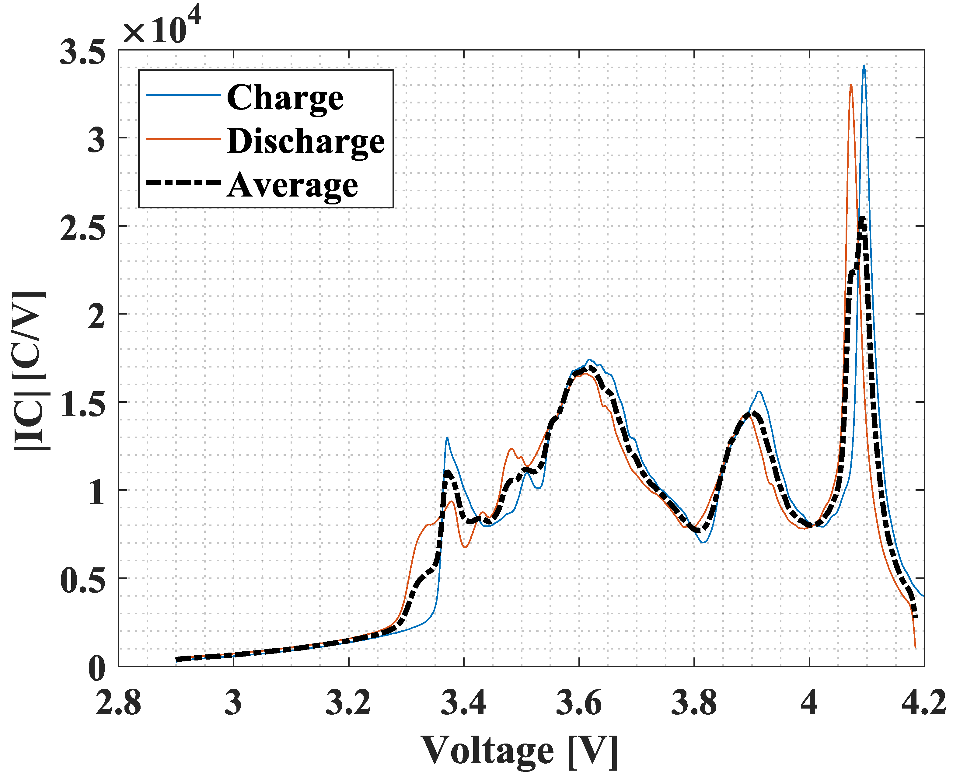
To simplify the hysteresis between charge and discharge processes, the average absolute of the charge and discharge IC curves, as illustrated in Figure 6, is used in constructing the model and to ensure a consistent and representative capacitance profile across the entire voltage range.

2.2. Model Validation

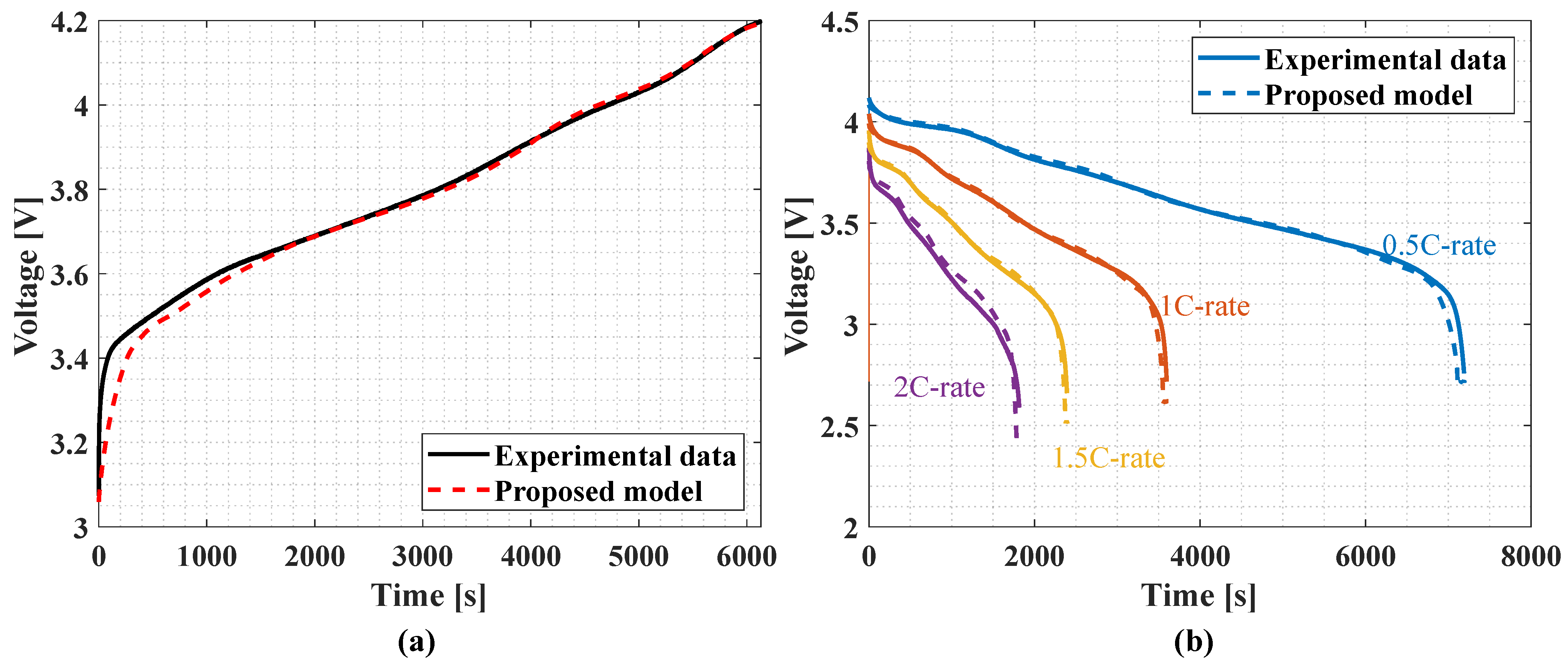
To validate the accuracy of the proposed model, a simulation schematic is implemented using the circuit simulation software, PLECS [30]. Experimental reference data are obtained from a cylindrical Li-ion cell (SDI, INR18650-29E, 3.6 V/2.85 Ah) under controlled laboratory conditions at 25 degrees Celsius. The cell is fully charged using CC at a 0.5 C-rate, followed by a constant voltage (CV) phase at 4.2 V with a cutoff current of 55 mA. Subsequently, the cell is discharged at multiple constant current levels—0.5 C, 1 C, 1.5 C, 2 C, and 3 C—until reaching a cutoff voltage of 2.5 V, also at 25 degrees Celsius ambient temperature.
The comparison results in Figure 7 illustrate that the terminal voltage profiles of the proposed model closely match the experimental data during both charging and discharging stages. At the end of discharge, the voltage deviation between the model and measured values is negligible. The mean absolute percentage error (MAPE), summarized in Table 1, indicates high accuracy, with a MAPE of 0.031% during the CC charging stage and 0.124% at the maximum 2 C-rate discharge. These results confirm that the variable capacitor model effectively captures battery behavior in both charge and discharge conditions.

3. CDT Calculation for Cell Balancing

One of the key advantages of the proposed variable capacitor model is its ability to provide direct and accurate calculations of the cell balancing time. In this study, the balancing time is selected as a representative use case to validate the CDT calculation procedure, as it inherently includes charge and discharge behavior during the balancing operation. In both active and passive balancing schemes, determining the charge transfer duration is essential for control design and efficiency evaluation. The model allows direct computation of the balancing time based on the capacitance and initial cell voltage conditions, without requiring simulations or hardware tests.
The equivalent capacitance, C e q , is defined based on the IC-to-voltage relationship of the battery cell, capturing its dynamic behavior during the balancing process. In practical balancing circuits, this capacitance works together with the circuit equivalent resistance, R e q , to determine the time constant. While C e q is determined by the battery characteristics, R e q depends on the specific balancing topology and hardware implementation. Detailed considerations of R e q for various methods are discussed in later sections.

3.1. Active Cell Balancing

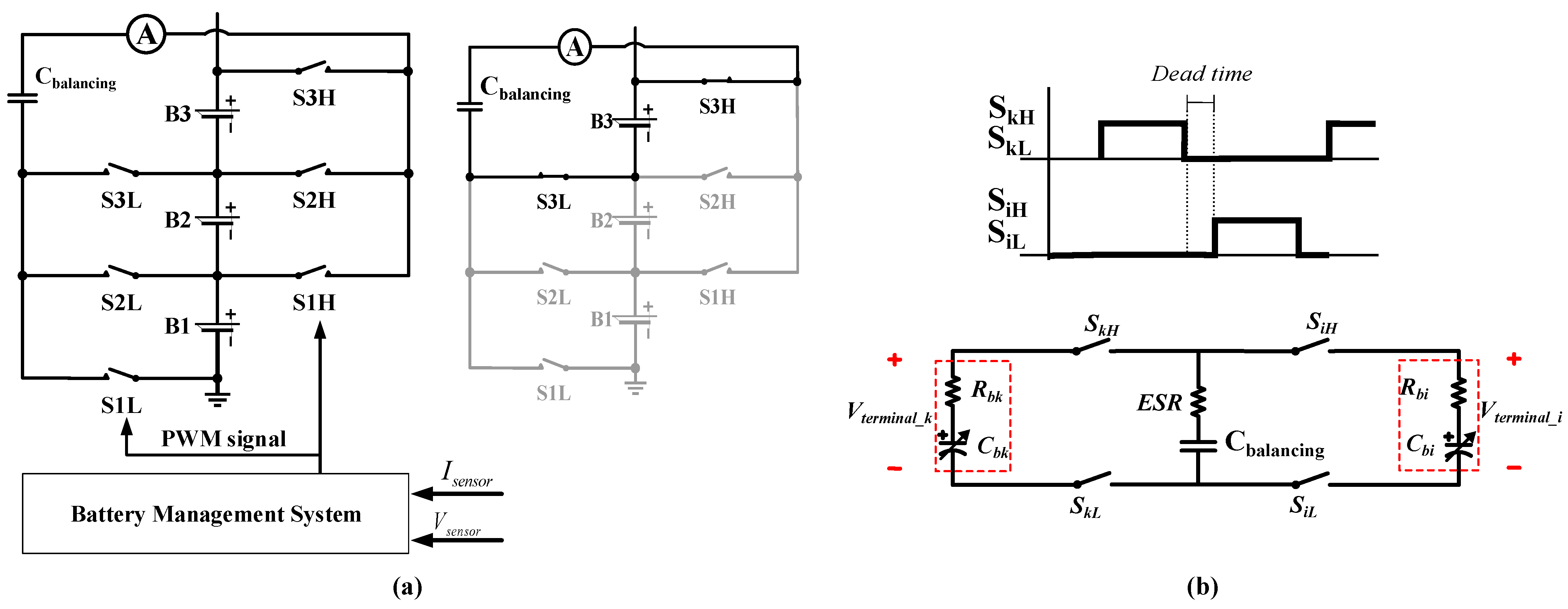
In active balancing systems, intermediate energy transfer circuits such as switching capacitors, switching inductors, or converters are used to transfer charge from higher voltage cells to lower ones [31]. Among these structures, switched-capacitors (SC) [32] are known to be attractive due to their high efficiency, modularity, and cost-effectiveness. In this work, a single switched-capacitor (SSC) balancing configuration [13] is adopted for the practical application of the proposed variable capacitor model. The SSC equalizer facilitates energy transfer between cells in a battery string through the operation of a balancing capacitor, C b a l a n c i n g , as shown in Figure 8a. During operation, the balancing capacitor, C b a l a n c i n g , connects to cells through switches, allowing charge to flow from the higher voltage cell to the lower voltage cell.
The proposed model is applied to this topology to enable simple and accurate calculation of the balancing time. In this case, the battery is modeled using a variable capacitor in series with an internal resistor to keep the structure simple and computationally efficient, as in Figure 8b. By doing this, CDT in the transfer process can be directly calculated using the R-C time constant.
To determine the charge-equivalent capacitance C e q of a cell, the model utilizes the IC profile. In this context, the IC is considered as the cell instantaneous capacitance, C b . As shown in Figure 9, C e q reflects the charge-equivalent capacitance of the cell across a specified voltage range of interest.
The trapezoidal integration method is employed to calculate C e q , offering a trade-off between numerical accuracy and computational simplicity [33]. This method is well suited when working with a discrete or experimentally obtained IC curve. The final expression for C e q is derived in
C e q ( V O C ) = Δ V O C [ C b n + C b 0 2 + m = 1 n 1 C b m ] V O C n V O C 0 ,
where C b m refers to the slope of the Q V O C curve at the m-th voltage step, representing how much charge is stored per unit voltage. C b 0 and C b n are the slope values at the start ( V b 0 ) and the end ( V b n ) of the voltage range, respectively. Δ V O C denotes the constant voltage interval between data points used for numerical integration.
On the other hand, the equivalent resistance [13] of the SSC balancing circuit in Figure 8 is found by
R e q = 1 f s C b a l a n c i n g 1 + e D / ( f s τ ) 1 e D / ( f s τ ) ,
τ = C b a l a n c i n g ( E S R + R b ) ,
where f s is the switching frequency of the balancing circuit, D is the duty ratio, and τ is the circuit time constant that can be calculated as the product of the balancing capacitor, C b a l a n c i n g , and the total resistance, which is the sum of the equivalent series resistance ( E S R ) of the balancing capacitor and the internal resistance of the cell, R b .
Based on the equivalent charge transfer analysis, the voltage after completing the balancing process is identified by
V b ( t ) = V 0 , i + C e q , k ( V 0 , k V 0 , i ) C e q , i + C e q , k ( 1 e t τ b ) ,
τ b = R e q C e q , i C e q , k C e q , i + C e q , k ,
where τ b is the balancing time constant, the subscripts i and k denote the lower and higher voltage cell, V 0 , i and V 0 , k denote the battery initial voltages, C e q , i and C e q , k represent the charge equivalent capacitance, and R e q is the equivalent resistance of the equalizer circuit given in Equation (3).
For a given target voltage difference between the two cells, Δ V b , defined by Equation (7), the total balancing time to achieve that balancing state can be calculated by Equation (8).
Δ V b = V b , k V b , i = ( V 0 , k V 0 , i ) e t b τ b
t b = τ b l n ( V 0 , k V 0 , i Δ V b )
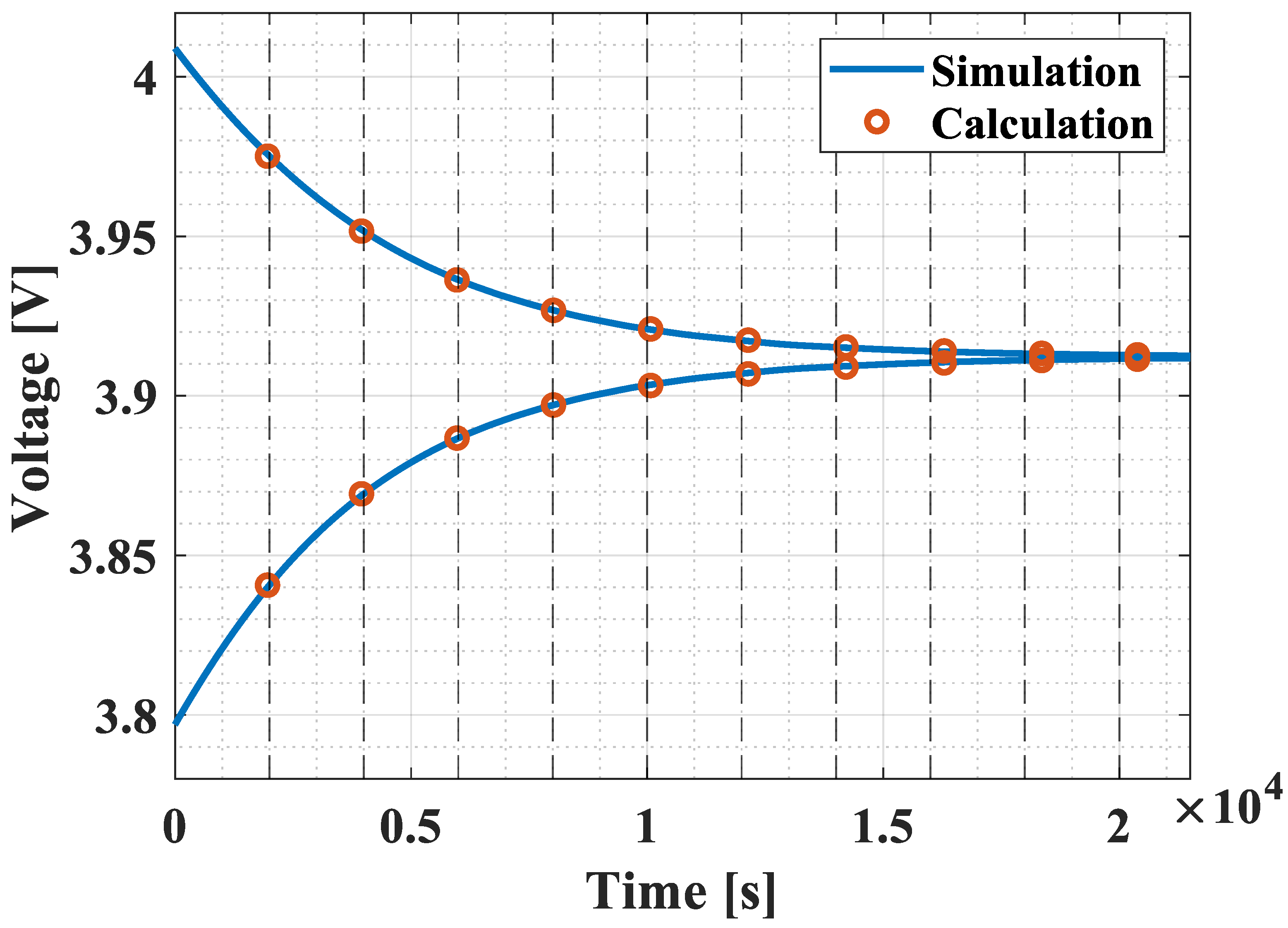
To validate the proposed calculation method, a PLECS simulation is conducted using two Li-ion batteries with initial SOC levels of 80% and 60%, connected in series and interfaced with an SSC balancing circuit. The battery model is equipped with cylindrical cell (SDI, INR18650-29E, 3.6 V/2.85 Ah) characteristics. The initial voltages of the cells are set to 4.0089 V and 3.7970 V, respectively.
The simulation parameters are configured as follows: the balancing capacitor is 2200 μF, the switching frequency is chosen as 20 kHz with a PWM duty of 0.45, the balancing capacitor ESR is 0.15 Ω, and the internal resistance of the cell is 0.035 Ω.
Figure 10 shows the gradual convergence of the two cell voltages, eventually reaching a balanced state. The equivalent resistance, R e q , of the SSC circuit is calculated as 0.8224 Ω by Equation (3). Using Equation (2), the charge-equivalent capacitance, C e q , for each cell is determined, which allows access to the balancing time through Equations (5) to (8). The computed balancing time is compared with the simulation results at several time instants, as summarized in Table 2. At each time instant, the OCV of the k-th and i-th cells are recorded, and the corresponding C e q values are calculated based on those voltages. The comparison shows that the calculated balancing time deviates from the simulated results by within 2.04%.
The calculated balancing time, t b , closely matches the simulation result, t s i m . This confirms the effectiveness of the proposed variable capacitor model for predicting the balancing behavior in active balancing systems.

3.2. Passive Cell Balancing

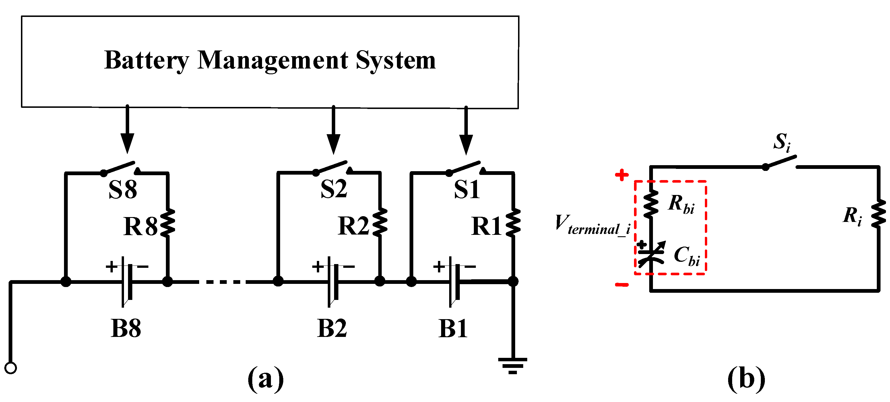
Although active balancing offers higher efficiency, passive balancing remains widely used in industry due to its simplicity and cost-effectiveness [34]. Figure 11a illustrates a typical passive cell balancing configuration. The balancing resistors discharge the cell with the highest voltage, reducing its voltage until it matches with the other cell voltages in the pack. This process continues until all the cells are balanced. In this scheme, the equivalent circuit incorporated with the proposed variable capacitor model in Figure 11b consists of a capacitor and resistors. It means that the balancing time can be directly determined simply by the R-C time constant. In this model, the charge equivalent capacitance is derived by Equation (2), while the equivalent resistance of this circuit is the sum of the discharging resistance, R i , and the internal resistance of a battery, R b i , for each cell.
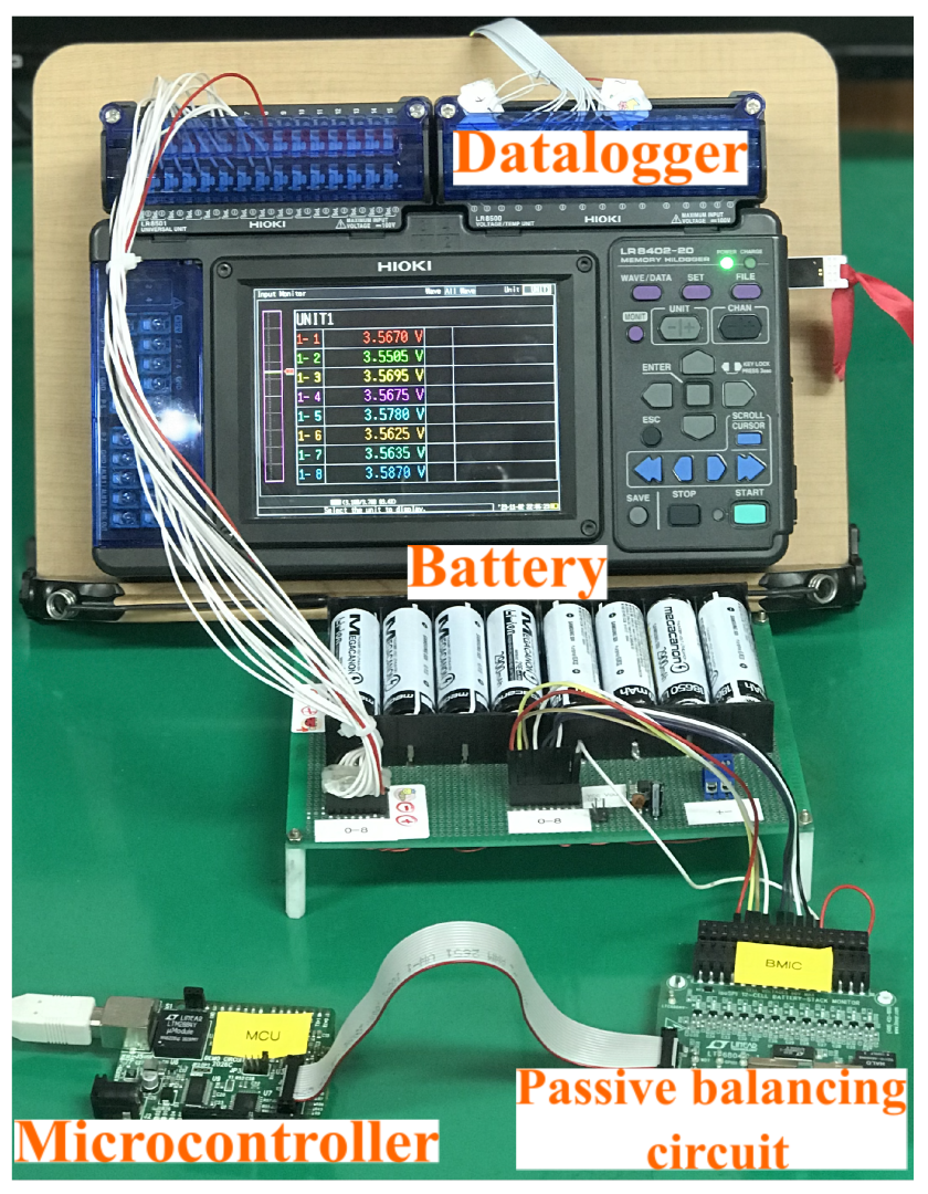
In order to validate this approach, an experiment on the passive balancing process is implemented at room temperature as illustrated in Figure 12. Eight cylindrical Li-ion cells (SDI, INR18650-29E, 3.6 V/2.85 Ah) with different initial SOC levels are controlled by a passive balancing chip (Analog Device, LTC6804) with a 27 Ω balancing resistor. Cell voltage data during operation are recorded using a data logger (HIOKI, LR8420). For the battery model, the internal resistance of a cell is measured as 35 mΩ by an impedance analyzer (ZIVE, SP10). By summing the series resistances, the equivalent resistance ( R e q ) is obtained as 27.355 Ω, including 0.32 Ω for a switch on-resistance and a small wiring resistance. The summary of the test setup is shown in Table 3.
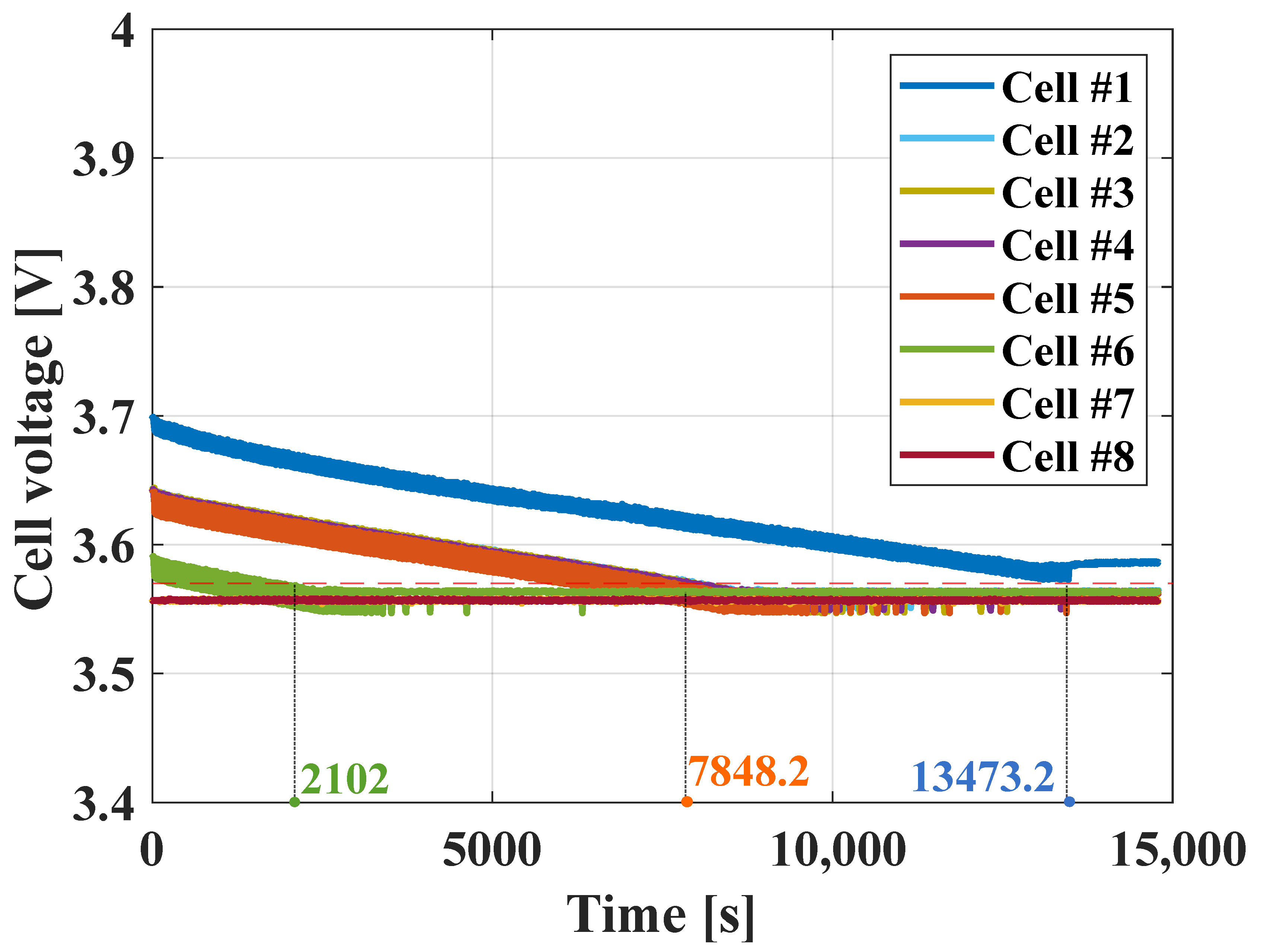
The cell voltage profiles observed throughout the balancing process are illustrated in Figure 13. Since cells #7 and #8 have the lowest initial voltages, they are not connected to discharge resistors. The remaining cells, with voltages exceeding those of cells #7 and #8, are connected to the discharging resistor until ΔV becomes less than 13 mV.
Table 4 presents a comparative analysis of the results obtained from the balancing time measurements and the proposed calculations, denoting t e x p and t c a l as the balancing times in the experiment and the calculation, respectively. The results substantiate that the calculation of the passive balancing time closely aligns with the actual results, with an error of 2.011%.

3.3. Discussion

Overall, the results from both active and passive balancing case studies confirm the effectiveness of the proposed variable capacitor model in providing effective and accurate calculation of the balancing time. The validated results demonstrate that the CDT can be determined by using the proposed calculation process with calculation errors of 2.04% and 2.01% for active and passive cell balancing, respectively. Besides its apparent simplicity, the proposed model proves to be a valuable tool in evaluating the performance of balancing circuits. It is not only suitable for circuit design tasks such as evaluating balancing algorithms or designing charging strategies, but also shows potential for practical deployment. By integrating with charging control schemes, the model enables real-time estimation of charge and balancing durations in the BMS. Its compatibility with both active and passive balancing architectures affirms its flexibility and applicability for diverse system designs.
The calculation process for determining the balancing time is summarized in Figure 14. First, the initial voltage, V b 0 , and target voltage, V b n , are defined. Using the IC curve of the cells, the charge-equivalent capacitance, C e q , is calculated via Equation (2). And then the equivalent resistance, R e q , is obtained based on the circuit type, using Equation (3) for the SSC, or as the total series resistance in the passive circuit. For various active balancing circuits, the equivalent circuit resistance is summarized in Table 5, with their circuit configurations shown in Figure 15. Finally, the balancing time, t b , is calculated by Equation (8).
The charge-equivalent capacitance, C e q , is formulated to capture the voltage-dependent dynamic behavior of lithium-ion cells during the balancing process in Section 3.1. While previous analyses focused on the SSC and passive balancing scheme, the concept of R e q can be extended to other active balancing architectures as well. For example, in a switched-inductor equalizer [35], R e q includes the inductor resistance ( R L ), the internal resistance of the battery cells ( R b i and R b i 1 ), and the duty cycle (D). For capacitor-based balancing topology [36], R e q is a function of the angular resonant frequency ( ω r ), the inductance (L), the capacitance (C), and the total parasitic resistance of each resonant loop (R), and depends on the switching frequency ( f s ). In transformer-based circuits [37], R e q is modeled using the duty cycle (D), battery internal resistance ( R b i ), and ESR of the output filter ( R L f i and R C f i ), as well as the on-resistance of MOSFET ( R o n i ), and the parasitic resistance in the resonant path ( R i ). By incorporating these topology-specific resistances, R e q , into the proposed battery model, the balancing time can be directly determined.
As batteries degrade, both the Q V O C relationship and the internal impedance require periodic updates to the model to maintain accuracy. By leveraging the IC curve [26,27,28,29,38], these aging-related changes can be easily incorporated, allowing the model to adapt over time. This adaptability is essential for ensuring the long-term reliability and relevance of the battery model across the entire operational lifespan.
Moreover, the proposed model structure, if combined with a lookup table (LUT) approach for implementing the variable capacitance C b ( V O C ) , offers a natural extension for including temperature effects. Multiple IC profiles can be experimentally obtained and stored in a LUT by temperature. During operation, C b ( V O C , T ) can be interpolated in real-time based on the measured cell temperature, T. Similarly, temperature-dependent models of internal resistance R b ( T ) allow the model to reflect realistic thermal behavior. As a result, the proposed model enables improved accuracy under varying thermal conditions.

4. Conclusions

This paper presents a battery modeling approach based on a variable capacitor that can be built from the IC curve. The proposed model enables direct determination of the balancing time through the R-C time constant, applicable to both active and passive balancing circuits. Simulation and experimental results demonstrate the model’s practicality and accuracy, validating its effectiveness for balancing time prediction. Owing to its simple structure, the model is well suited for real-time BMS applications. Furthermore, utilization of the IC curve facilitates easy adaptation to battery aging, as evolving IC curves allow periodic updates. This makes the proposed model a scalable and flexible solution for long-term battery monitoring and control. Future work should focus on a more in-depth analysis of how temperature and aging effects influence charge-equivalent capacitance and CDT calculation accuracy. In addition, the influence of hysteresis effects on the IC-derived capacitance profile warrants further study to enhance model performance.

Author Contributions

Conceptualization, N.-T.P. and S.-J.C.; data curation, N.-T.P.; funding acquisition, S.-J.C.; investigation, N.-T.P.; methodology, N.-T.P., S.K., and S.-J.C.; project administration, S.-J.C.; resources, S.-J.C.; supervision, S.-J.C.; validation, N.-T.P., S.K., and S.-J.C.; visualization, N.-T.P., S.K., and S.-J.C.; writing—original draft, N.-T.P.; writing—review and editing, S.K. and S.-J.C. All authors have read and agreed to the published version of the manuscript.

Funding

This research (P0025291) was supported by the Ministry of Trade, Industry & Energy (MOTIE), Korea Institute for Advancement of Technology (KIAT) through the Encouragement Program for The Innovation Cluster Development of the Regions.

Data Availability Statement

The original contributions presented in the study are included in the article, further inquiries can be directed to the corresponding author.

Conflicts of Interest

The authors declare no conflicts of interest.

References

  1. Einhorn, M.; Roessler, W.; Fleig, J. Improved performance of serially connected Li-ion batteries with active cell balancing in electric vehicles. IEEE Trans. Veh. Technol. 2011, 60, 2448–2457. [Google Scholar] [CrossRef]
  2. Dubarry, M.; Devie, A.; Liaw, B.Y. Cell-balancing currents in parallel strings of a battery system. J. Power Sources 2016, 321, 36–46. [Google Scholar] [CrossRef]
  3. Yang, N.; Zhang, X.; Shang, B.; Li, G. Unbalanced discharging and aging due to temperature differences among the cells in a lithium-ion battery pack with parallel combination. J. Power Sources 2016, 306, 733–741. [Google Scholar] [CrossRef]
  4. Zheng, Y.; Wang, C.; Sang, S.; Yu, S. Estimation of remaining energy and available power for Li-Ion battery packs considering energy consumption by heat convection. J. Power Electron. 2023, 23, 139–148. [Google Scholar] [CrossRef]
  5. Wang, Y.; Chen, Z. A framework for state-of-charge and remaining discharge time prediction using unscented particle filter. Appl. Energy 2020, 260, 114324. [Google Scholar] [CrossRef]
  6. Ren, D.; Lu, L.; Shen, P.; Feng, X.; Han, X.; Ouyang, M. Battery remaining discharge energy estimation based on prediction of future operating conditions. J. Energy Storage 2019, 25, 100836. [Google Scholar] [CrossRef]
  7. Bak, Y. Hardware-simulator development and implementation of battery charger for personal mobility devices. J. Power Electron. 2023, 23, 211–218. [Google Scholar] [CrossRef]
  8. Choi, J.; Bak, Y. Dynamic characteristic improvement of battery chargers for personal mobility devices using sliding mode control. J. Power Electron. 2024, 24, 140–146. [Google Scholar] [CrossRef]
  9. Choi, H. Overview of charging technology evolution in smartphones. J. Power Electron. 2023, 23, 1931–1941. [Google Scholar] [CrossRef]
  10. Pedram, M.; Wu, Q. Design considerations for battery-powered electronics. In Proceedings of the 36th Annual ACM/IEEE Design Automation Conference, New Orleans, LA, USA, 21–25 June 1999; pp. 861–866. [Google Scholar]
  11. Baronti, F.; Roncella, R.; Saletti, R. Performance comparison of active balancing techniques for lithium-ion batteries. J. Power Sources 2014, 267, 603–609. [Google Scholar] [CrossRef]
  12. Chen, M.; Rincon-Mora, G.A. Accurate electrical battery model capable of predicting runtime and IV performance. IEEE Trans. Energy Convers. 2006, 21, 504–511. [Google Scholar] [CrossRef]
  13. La, P.H.; Choi, S.J. Direct cell-to-cell equalizer for series battery string using switch-matrix single-capacitor equalizer and optimal pairing algorithm. IEEE Trans. Power Electron. 2022, 37, 8625–8639. [Google Scholar] [CrossRef]
  14. Bouchhima, N.; Schnierle, M.; Schulte, S.; Birke, K.P. Active model-based balancing strategy for self-reconfigurable batteries. J. Power Sources 2016, 322, 129–137. [Google Scholar] [CrossRef]
  15. Yang, S.; Zhang, S. Energy balance control of multi group lithium ion batteries under internet of things technology. IEEE Access 2024, 12, 102784–102797. [Google Scholar] [CrossRef]
  16. Khan, A.B.; Choi, W. Optimal charge pattern for the high-performance multistage constant current charge method for the li-ion batteries. IEEE Trans. Energy Convers. 2018, 33, 1132–1140. [Google Scholar] [CrossRef]
  17. Jiang, L.; Li, Y.; Huang, Y.; Yu, J.; Qiao, X.; Wang, Y.; Huang, C.; Cao, Y. Optimization of multi-stage constant current charging pattern based on Taguchi method for Li-Ion battery. Appl. Energy 2020, 259, 114148. [Google Scholar] [CrossRef]
  18. Wang, Y.; Tian, J.; Sun, Z.; Wang, L.; Xu, R.; Li, M.; Chen, Z. A comprehensive review of battery modeling and state estimation approaches for advanced battery management systems. Renew. Sustain. Energy Rev. 2020, 131, 110015. [Google Scholar] [CrossRef]
  19. Tamilselvi, S.; Gunasundari, S.; Karuppiah, N.; Razak RK, A.; Madhusudan, S.; Nagarajan, V.M.; Sathish, T.; Shamim, M.Z.M.; Saleel, C.A.; Afzal, A. A review on battery modelling techniques. Sustainability 2021, 13, 10042. [Google Scholar] [CrossRef]
  20. Bruch, M.; Millet, L.; Kowal, J.; Vetter, M. Novel method for the parameterization of a reliable equivalent circuit model for the precise simulation of a battery cell’s electric behavior. J. Power Sources 2021, 490, 229513. [Google Scholar] [CrossRef]
  21. Hu, X.; Li, S.; Peng, H. A comparative study of equivalent circuit models for Li-ion batteries. J. Power Sources 2012, 198, 359–367. [Google Scholar] [CrossRef]
  22. Pham, N.T.; Kim, J.H.; Choi, S.J. Novel battery model employing variable capacitor for effective description of SOC behavior. In Proceedings of the 2024 IEEE Applied Power Electronics Conference and Exposition (APEC), Long Beach, CA, USA, 25–29 February 2024; IEEE: Piscataway, NJ, USA, 2024; pp. 3035–3040. [Google Scholar]
  23. Khan, A.B.; Pham, V.L.; Nguyen, T.T.; Choi, W. Multistage constant-current charging method for Li-Ion batteries. In Proceedings of the 2016 IEEE Transportation Electrification Conference and Expo, Asia-Pacific (ITEC Asia-Pacific), Busan, Republic of Korea, 1–4 June 2016; IEEE: Piscataway, NJ, USA, 2016; pp. 381–385. [Google Scholar]
  24. Johnson, V. Battery performance models in ADVISOR. J. Power Sources 2002, 110, 321–329. [Google Scholar] [CrossRef]
  25. Tian, N.; Fang, H.; Chen, J.; Wang, Y. Nonlinear double-capacitor model for rechargeable batteries: Modeling, identification, and validation. IEEE Trans. Control Syst. Technol. 2020, 29, 370–384. [Google Scholar] [CrossRef]
  26. Dubarry, M.; Liaw, B.Y. Identify capacity fading mechanism in a commercial LiFePO4 cell. J. Power Sources 2009, 194, 541–549. [Google Scholar] [CrossRef]
  27. Dubarry, M.; Svoboda, V.; Hwu, R.; Liaw, B.Y. Capacity and power fading mechanism identification from a commercial cell evaluation. J. Power Sources 2007, 165, 566–572. [Google Scholar] [CrossRef]
  28. Anseán, D.; García, V.M.; González, M.; Blanco-Viejo, C.; Viera, J.C.; Pulido, Y.F.; Sánchez, L. Lithium-ion battery degradation indicators via incremental capacity analysis. IEEE Trans. Ind. Appl. 2019, 55, 2992–3002. [Google Scholar] [CrossRef]
  29. Schaltz, E.; Stroe, D.I.; Nørregaard, K.; Ingvardsen, L.S.; Christensen, A. Incremental capacity analysis applied on electric vehicles for battery state-of-health estimation. IEEE Trans. Ind. Appl. 2021, 57, 1810–1817. [Google Scholar] [CrossRef]
  30. Plexim GmbH. PLECS User Manual; Plexim GmbH: Zurich, Switzerland, 2025; Available online: https://www.plexim.com (accessed on 1 August 2025).
  31. Daowd, M.; Omar, N.; Van Den Bossche, P.; Van Mierlo, J. Passive and active battery balancing comparison based on MATLAB simulation. In Proceedings of the 2011 IEEE Vehicle Power and Propulsion Conference, Chicago, IL, USA, 6–9 September 2011; IEEE: Piscataway, NJ, USA, 2011; pp. 1–7. [Google Scholar]
  32. Ye, Y.; Cheng, K.W.E.; Fong, Y.C.; Xue, X.; Lin, J. Topology, modeling, and design of switched-capacitor-based cell balancing systems and their balancing exploration. IEEE Trans. Power Electron. 2016, 32, 4444–4454. [Google Scholar] [CrossRef]
  33. Chapra, S.C.; Canale, R.P. Numerical Methods for Engineers; Mcgraw-Hill: New York, NY, USA, 2011; Volume 1221. [Google Scholar]
  34. Omariba, Z.B.; Zhang, L.; Sun, D. Review of battery cell balancing methodologies for optimizing battery pack performance in electric vehicles. IEEE Access 2019, 7, 129335–129352. [Google Scholar] [CrossRef]
  35. Ben-Yaakov, S.; Evzelman, M. Generic and unified model of switched capacitor converters. In Proceedings of the 2009 IEEE Energy Conversion Congress and Exposition, San Jose, CA, USA, 20–24 September 2009; IEEE: Piscataway, NJ, USA, 2009; pp. 3501–3508. [Google Scholar]
  36. Ye, Y.; Cheng, K.W.E. Analysis and design of zero-current switching switched-capacitor cell balancing circuit for series-connected battery/supercapacitor. IEEE Trans. Veh. Technol. 2017, 67, 948–955. [Google Scholar] [CrossRef]
  37. Li, S.; Mi, C.C.; Zhang, M. A high-efficiency active battery-balancing circuit using multiwinding transformer. IEEE Trans. Ind. Appl. 2012, 49, 198–207. [Google Scholar] [CrossRef]
  38. Peng, J.; Zhao, X.; Ma, J.; Meng, D.; Jia, S.; Zhang, K.; Gu, C.; Ding, W. State of Health Estimation of Li-Ion Battery via Incremental Capacity Analysis and Internal Resistance Identification Based on Kolmogorov–Arnold Networks. Batteries 2024, 10, 315. [Google Scholar] [CrossRef]
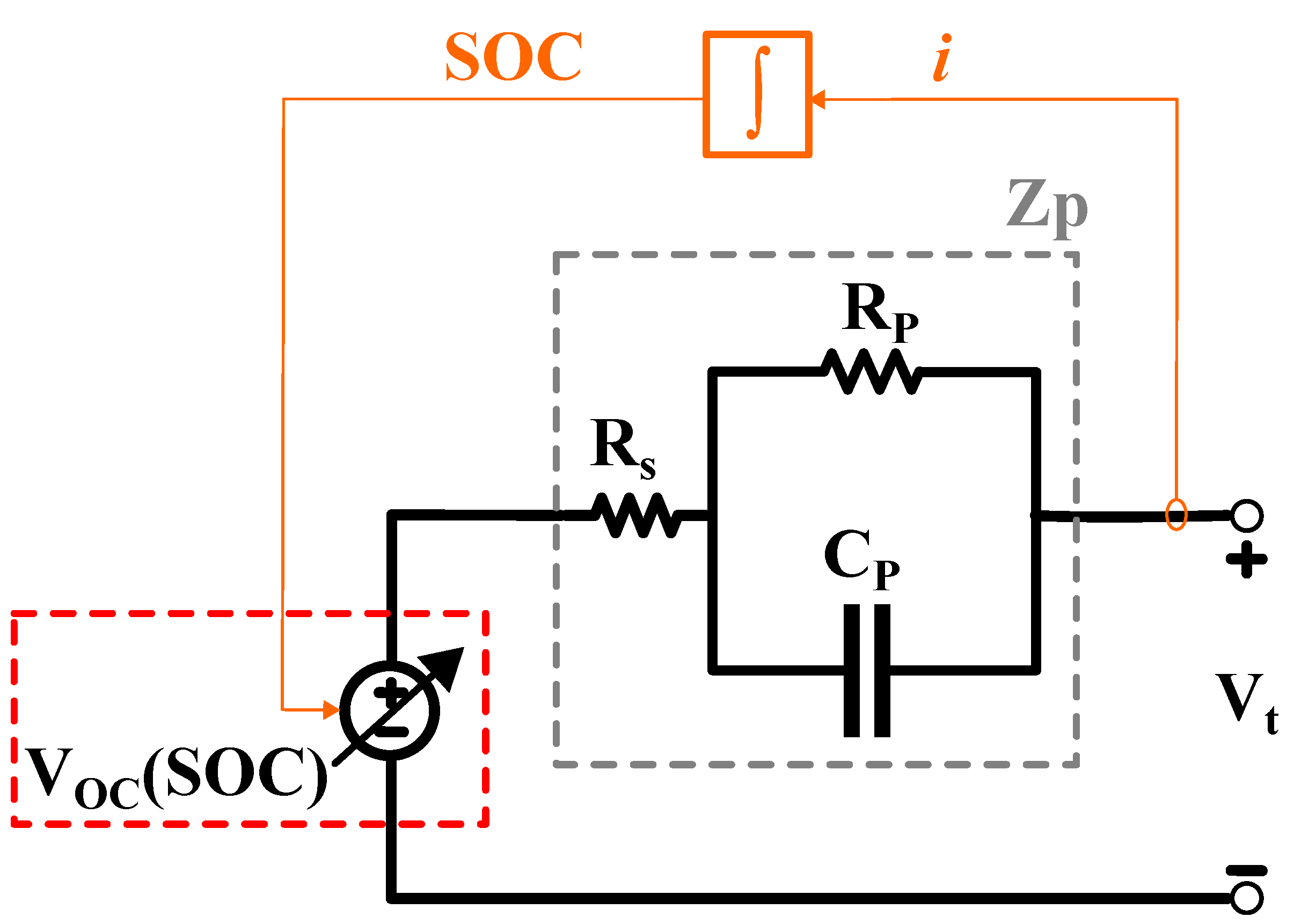
Figure 1. Variable voltage source battery model.
Batteries 11 00300 g001
Figure 2. Battery model to describe the charge–discharge behavior. (a) Voltage source-based model; (b) Capacitor-based model.
Batteries 11 00300 g002
Figure 3. Conventional capacitor-based battery model (a) Simple RC model [23]; (b) RC model [24]; (c) Non-linear double-capacitor model [25].
Batteries 11 00300 g003
Figure 4. Proposed variable capacitor battery model.
Batteries 11 00300 g004
Figure 5. Battery charge–discharge profile according to the open circuit voltage. (a) Capacity; (b) Incremental capacity curve.
Batteries 11 00300 g005
Figure 6. Absolute averaging process for the charge and discharge IC curve.
Batteries 11 00300 g006
Figure 7. Terminal voltage comparison of the experimental data and the proposed model simulation (a) 0.5 C-rate CC charging; (b) CC discharging in various C rates.
Batteries 11 00300 g007
Figure 8. Single switched-capacitor equalizer. (a) Topology structure and operation; (b) Its equivalent circuit.
Batteries 11 00300 g008
Figure 9. The charge-equivalent capacitance over a voltage range using the trapezoidal method.
Batteries 11 00300 g009
Figure 10. Voltage waveform of the balancing process.
Batteries 11 00300 g010
Figure 11. Passive cell balancing circuit. (a) Topology structure; (b) Equivalent circuit.
Batteries 11 00300 g011
Figure 12. Experimental setup of the passive cell balancing test.
Batteries 11 00300 g012
Figure 13. Cell voltages of the passive balancing experiments.
Batteries 11 00300 g013
Figure 14. Balancing time calculation process.
Batteries 11 00300 g014
Figure 15. Various active balancing circuits. (a) Switched-inductor [35]; (b) Switched-capacitor [36]; (c) Multiwinding transformer [37].
Batteries 11 00300 g015
Table 1. Terminal voltage error for the test in Figure 7.
StageCurrentMAPE [%]
Charge0.5 C-rate0.031
Discharge0.5 C-rate0.040
1 C-rate0.046
1.5 C-rate0.033
2 C-rate0.124
Table 2. Comparative result for the active balancing time.
Time [s] V b , k [V] V b , i [V] C eq , k [F] C eq , i [F] Δ V b [mV] t sim [s] t b [s] t error [%]
20003.9753.84112,002.639283.09134.4320001959.112.04
40003.9523.86911,490.829100.4082.3240003949.031.27
60003.9363.88711,183.379039.3449.5860005971.650.47
80003.9273.89711,004.619022.7629.6780008016.20−0.20
10,0003.9213.90310,900.809020.1417.7210,00010,073.07−0.73
12,0003.9173.90710,840.229021.1410.5712,00012,140.47−1.17
14,0003.9153.90910,804.689022.646.3114,00014,209.55−1.50
16,0003.9143.91010,783.589023.853.7616,00016,289.74−1.81
18,0003.9133.91110,771.219024.682.2518,00018,355.77−1.98
20,0003.9133.91210,763.679025.191.3620,00020,383.05−1.92
Table 3. Summary of experimental equipment and test conditions of passive balancing.
Experimental ItemSpecification
Battery cellSDI, INR18650-29E, 3.6 V/2.85 Ah
TemperatureRoom temperature
Passive balancing chipAnalog device, LTC6804
Data loggerHIOKI, LR8420
Impedance analyzerZive SP10
Table 4. Comparative results for the passive balancing time.
Cell SOC init SOC target V init [V] V target [V] C eq [F] R eq [ Ω ] t cal [s] t exp [s] t error [%]
#10.490.323.6983.5713,731.57427.35513,232.04613,473.21.790
#2, #3, #40.420.323.6433.5714,029.86727.3557768.5877848.21.014
#50.340.323.593.5714,031.20727.3552144.2722102−2.011
#6, #70.30-3.557------
Table 5. Equivalent resistance, R e q , expressions for different active balancing topologies.
Active Balancing TopologySwitched-Inductor [35]Switched-Capacitor [36]Multiwinding Transformer [37]
R e q R L + ( 1 D ) R b i 1 + D R b i 1 + e β π / ω r C f s ( 1 e β π / ω r ) where  β = R / ( 2 L ) R B L i + 1 D D R C f i + 1 D ( R i + R o n i ) where  R B L i = R b i + R L f i
Disclaimer/Publisher’s Note: The statements, opinions and data contained in all publications are solely those of the individual author(s) and contributor(s) and not of MDPI and/or the editor(s). MDPI and/or the editor(s) disclaim responsibility for any injury to people or property resulting from any ideas, methods, instructions or products referred to in the content.