Article

A State-of-Charge-Frequency Control Strategy for Grid-Forming Battery Energy Storage Systems in Black Start

1
Polytechnic Institute, Zhejiang University, Hangzhou 310015, China
2
College of Electrical Engineering, Zhejiang University, Hangzhou 310027, China
*
Author to whom correspondence should be addressed.
Batteries 2025, 11(8), 296; https://doi.org/10.3390/batteries11080296
Submission received: 3 July 2025 / Revised: 27 July 2025 / Accepted: 31 July 2025 / Published: 4 August 2025
(This article belongs to the Section Battery Modelling, Simulation, Management and Application)

Abstract

As the penetration of intermittent renewable energy sources continues to increase, ensuring reliable power system and frequency stability is of importance. Battery energy storage systems (BESSs) have emerged as an important solution to mitigate these challenges by providing essential grid support services. In this context, a state-of-charge (SOC)-frequency control strategy for grid-forming BESSs is proposed to enhance their role in stabilizing grid frequency and improving overall system performance. In the system, the DC-link capacitor is regulated to maintain the angular frequency through a matching control scheme, emulating the characteristics of the rotor dynamics of a synchronous generator (SG). Thereby, the active power control is implemented in the control of the DC/DC converter to further regulate the grid frequency. More specifically, the relationship between the active power and the frequency is established through the SOC of the battery. In addition, owing to the inevitable presence of differential operators in the control loop, a high-gain observer (HGO) is employed, and the corresponding parameter design of the proposed method is elaborated. The proposed strategy simultaneously achieves frequency regulation and implicit energy management by autonomously balancing power output with available battery capacity, demonstrating a novel dual benefit for sustainable grid operation. To verify the effectiveness of the proposed control strategy, a 0.5-Hz frequency change and a 10% power change are carried out through simulations and also on a hardware-in-the-loop (HIL) platform.

1. Introduction

The rapid integration of inverter-interfaced renewable energy sources, such as wind and solar, has significantly reduced system inertia, increasing frequency fluctuations and challenging grid stability [1]. To address these issues, grid-forming (GFM) control has emerged as a promising solution by emulating the voltage and frequency forming capabilities of synchronous generators, thus providing synthetic inertia and improving dynamic performance in low-inertia systems [2,3]. Among various technologies, battery energy storage systems (BESSs) are especially suitable for GFM control due to their fast response, bidirectional power flow, and high controllability [4,5,6]. Compared with renewable sources like wind turbines (WT) and photovoltaic (PV) systems, which are inherently intermittent and difficult to predict, BESSs offer dispatchable and stable power output, while actively regulating both active and reactive power, enabling critical functions like black start, frequency regulation, and fault recovery [7,8].
Among the various applications of the GFM-controlled BESS, black start is of importance due to its stringent operational requirements. In the absence of an external grid, the black start unit must independently establish and maintain voltage and frequency references, which traditional grid-following (GFL) inverters cannot achieve [9]. Leveraging their fast dynamics and controllability, the GFM-BESS becomes a viable solution, in terms of inertial emulation and reliable system restoration capabilities.
In recent years, significant attention has been given to the application of the GFM-controlled BESS in black start scenarios. In [10], a WT-BESS black start system based on virtual synchronous generator (VSG) control was developed with an improved frequency synchronization method that enables secondary frequency regulation, effectively reducing frequency and voltage deviations. Similarly, in [11,12] the BESS for supporting wind power systems during black start was studied. More specifically, ref. [11] focused on mitigating frequency deviations and providing excitation voltage—albeit without detailing the control structure. In [12], a power synchronization control (PSC) with additional damping and virtual inertia in both the BESS and offshore wind farm (OWF) was presented, where a nonlinear large-signal dynamic analysis was also provided to evaluate the black start performance. Control strategies combining energy storage and reactive power compensation devices are also prominent. For instance, in [13], a static synchronous compensator (STATCOM) integrated with the BESS was introduced, where the BESS employs a PSC for active power balancing, and the STATCOM provides fast dynamic reactive power support. Similarly, ref. [14] presented a three-loop control approach for precise control of BESS output power and voltage, enabling seamless transitions between grid-connected and islanded modes.
As an alternative, enhancing traditional droop control is also attractive. In [15], a secondary control loop was added to the conventional droop control to restore voltage and frequency to nominal values. Moreover, in [16], the use of variable-frequency droop coefficients in a GFM-controlled BESS was explored, verifying improvements in grid integration, fault response, and virtual inertia support through case studies. To address transient impacts during black start, ref. [17] developed a voltage control scheme incorporating a variable-slope transfer function within the reactive power–voltage droop control, effectively suppressing inrush currents during voltage restoration. Similarly, ref. [18] has presented an integrated control strategy, which combines a voltage droop control with frequency and voltage coordination to simultaneously suppress overvoltages and eliminate transformer inrush currents. Additionally, an inrush current mitigation by adjusting reference regulators in a cascaded control structure was in focus in [19], reducing the peak and decay of energization-induced surges.
However, the above did not fully use the capability of the storage energy capacity, where the finite energy capacity of batteries requires careful state-of-charge (SOC) monitoring and management to ensure continuous operation, particularly during long restoration processes. While some studies have considered SOC to a certain extent, explicit integration of SOC into the control loops remains largely unexplored [20], leading to suboptimal system performance. In particular, existing GFM-BESS black start studies rarely incorporate SOC directly within the control architecture, resulting in limited energy-aware frequency support. This research gap motivates the present work. Notably, incorporating SOC into the control loop not only helps maintain system stability but also balances power output with energy availability, which is the key to sustainable GFM operation in black start scenarios. This paper addresses this critical gap by proposing a novel SOC-frequency control strategy specifically designed for GFM-BESSs operating in black start scenarios. By leveraging the SOC as a dynamic variable, a droop-like relationship is established between the battery output power and the system frequency. Compared to traditional droop control and virtual inertia methods, the proposed SOC-frequency mechanism not only provides frequency regulation and synthetic inertia, but also explicitly considers energy availability, thus enabling more effective and sustainable power balancing. This implicit energy management function complements and extends existing approaches by integrating power output adjustments with real-time SOC feedback, which is essential for long-duration black start operations. To the best of our knowledge, this is one of the first studies to explicitly embed SOC into the frequency control loop of GFM-BESSs for black start applications, thus filling an important research gap and offering practical value for resilient power system restoration.
The remainder of this paper is organized as follows: Section 2 presents a description of the black start system model with a demonstration simulation of the black start operation. Section 3 details the proposed SOC-frequency control strategy and the inverter’s matching control scheme. Section 4 analyzes simulation results and Section 5 shows the hardware-in-the-loop (HIL) tests under various operating conditions to verify the effectiveness of the control strategy. Finally, Section 6 concludes the paper.
In light of the above, this paper proposes an SOC-frequency control strategy tailored for GFM-BESSs in black start scenarios. The main research objectives are summarized as follows:
  • To establish an SOC-frequency control mechanism that explicitly integrates the state-of-charge (SOC) into the control loop, enabling autonomous power adjustment according to real-time frequency deviations.
  • To enhance frequency regulation and implicit energy management simultaneously, achieving a dual benefit of improved dynamic frequency support and sustainable energy utilization during long-duration black start processes.
  • To design and optimize the control parameters, including the high-gain observer (HGO), ensuring stable and robust performance under varying frequency and load conditions.
  • To validate the proposed strategy through simulations and HIL experiments, demonstrating its practical feasibility beyond purely simulation-based studies.

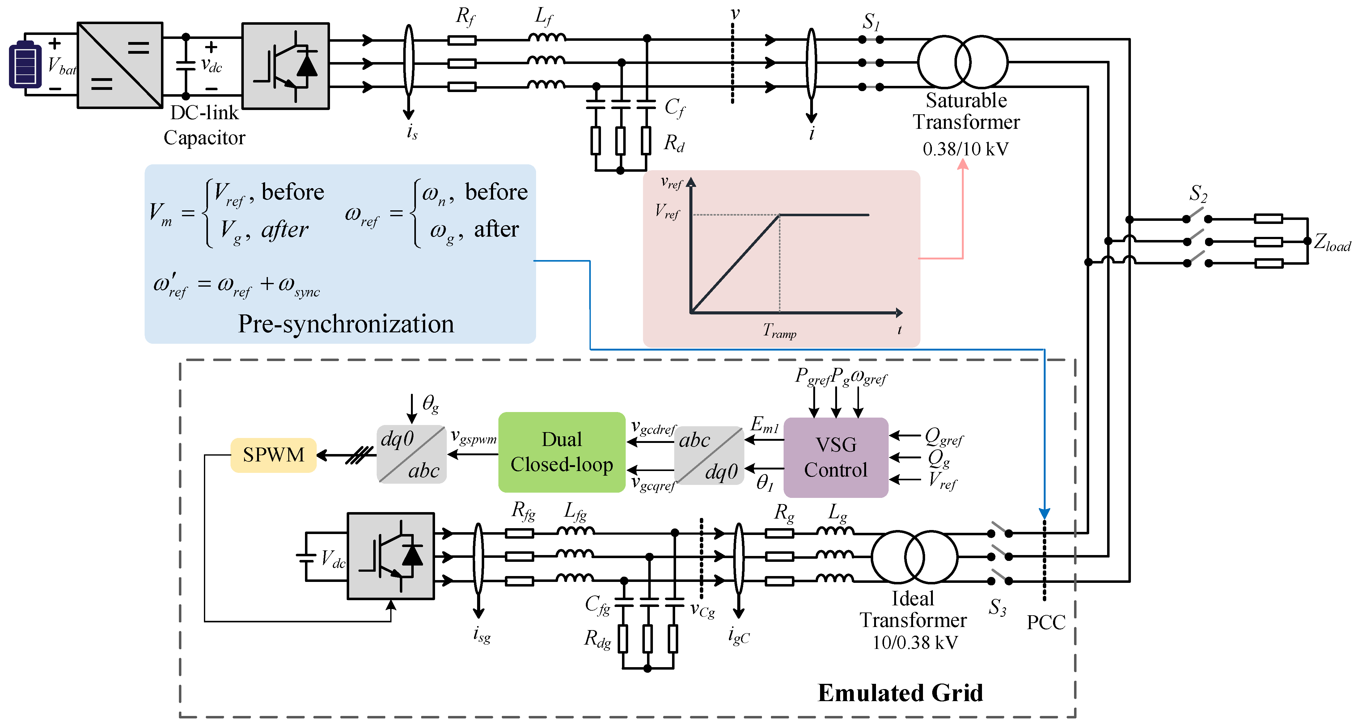
2. System Description

It is important to note that in this study, the energy storage battery serves as the black start power source and undergoes three stages: transformer and load energization, pre-synchronization, and grid-connection. To prevent transformer damage due to inrush currents, a soft-start strategy is implemented by setting the inverter reference voltage as a ramp during the initial energization phase [21]. The pre-synchronization stage primarily ensures phase alignment at the point of common coupling (PCC), with the phase difference reduced within the allowable threshold before the closure of the grid-connection relay [22]. At the moment of the grid-connection, the voltage and frequency references of the inverter side should be modified to the same as the grid side. The system model based on this process is illustrated in Figure 1, with the key parameters being detailed in Table 1. Figure 2 presents the system waveforms throughout the black start procedure: soft load energization completes at 0.5 s, pre-synchronization begins at 1.0 s, and connection to the grid, which is emulated via the VSG control, occurs at 1.5 s.
As shown in Figure 2, during the initial 0.5 s the BESS begins the black start operation with the load in which the transformer undergoes the soft-start process. The voltage magnitude at the PCC exhibits a ramp-up characteristic. At 1.0 s, the pre-synchronization begins, accompanied by minor frequency undershoots, as shown in Figure 2d. At 1.5 s, grid-connection is established, after which the active power Pe, phase-a current isa, DC-link voltage vdc and frequency f reach the steady state, but all show oscillations. Except for the soft-start, the amplitude of va almost remains constant. Simulations and analysis in the above demonstrate that the studied BESS possesses the capability for black start.

3. Proposed Control Strategies

This section introduces the control structure of the system. On the DC side, a bidirectional buck-boost converter is used to increase the battery voltage before interfacing with the DC-AC inverter.

3.1. DC-AC Inverter Control

3.1.1. Matching Control

The matching control leverages the DC-link capacitor to emulate the rotor dynamics of the SG, thereby providing both damping and inertia. The specific equivalence is described as follows. For an SG rotor, there is
J ω n d ω g d t + D ω n ( ω g ω n ) = P m P E
in which wn denotes the rated value of the angular frequency, wg is the grid angular frequency, J and D are the moment of inertia and damping coefficient, respectively. Moreover, Pm is the prime motor output power, and PE is the electromagnetic power. The dynamics of the DC-link capacitor can be described as
C d c v d c d v d c d t = P s P e
where Cdc is the DC-link capacitor, vdc denotes the instantaneous voltage of the capacitor, Ps and Pe are the power injected from the power source and inverter output power, respectively.
According to the similarity between Equations (1) and (2), several studies have explored the equivalence between the DC-link capacitor and the SG rotor by coupling the DC-link voltage vdc with the inverter’s angular frequency w [23,24]. More specifically, in Equation (1), if the inertia and damping coefficients are reformulated as
J = K J C dc 2
D = K D C dc 2
with KT being the voltage tracking coefficient, KJ being the inertia emulation coefficient and KD being the damping coefficient. Then, the relationship between the DC-link voltage and the frequency can be established as
ω = ω r e f + s + K T K J s + K D ( v d c ) 2 ( v d c r e f ) 2
where w is the inverter angular frequency, wref denotes the reference angular frequency and vdcref represents the reference DC-link voltage. Notably, compared to directly coupling vdc and w using a proportional controller in [2], the method of (5) effectively eliminates steady state error. The corresponding control block diagram is then shown in Figure 3.
Furthermore, since the matching control achieves synchronization via the DC-link capacitor, it requires active power regulation at the front-end stage. This inherent characteristic makes it well-suited for back-to-back converter configurations, enabling simultaneous DC voltage stabilization and grid frequency support.

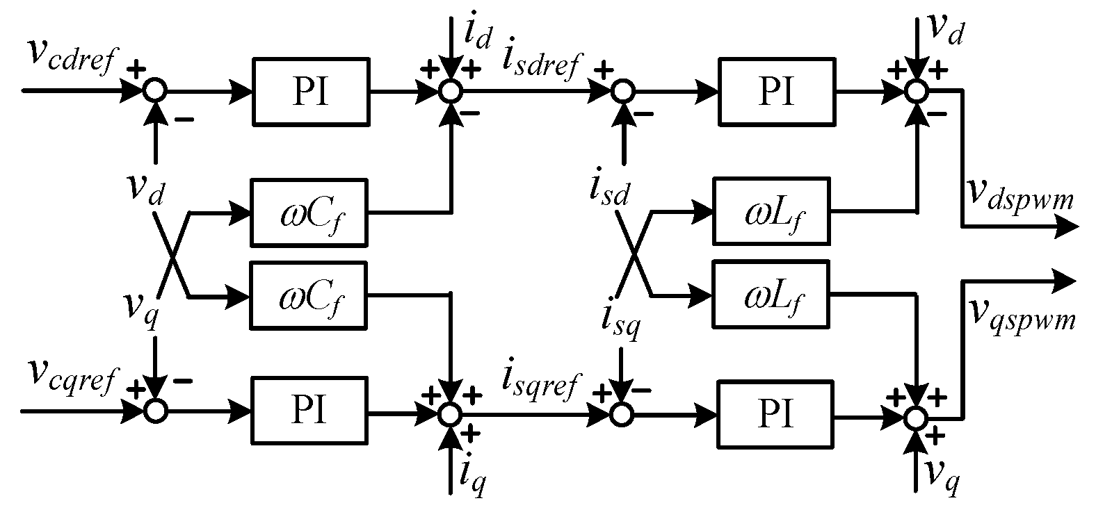
3.1.2. Dual Closed-Loop Control

To improve the voltage and current control as well as enhance the system dynamic performance, a dual closed-loop control structure is implemented following the matching control, as shown in Figure 3 and detailed in Figure 4. The voltages vdspwm and vqspwm serve as modulation voltage inputs to the SPWM generator.
Here, vd and vq are the d and q axis components of the filter capacitor voltage, vcdref and vcqref represent the corresponding reference values. Similarly, is refers to the current output from the inverter bridge arms, with isref being the reference value, while i represents the current after the LC filter. In Figure 4, the subscripts “d” and “q” denote the respective d and q axis components.

3.2. DC-DC Converter Control

As discussed in the above, the DC/DC converter is responsible for active power control. In conventional control schemes, a cascaded structure is adopted, consisting of an outer loop for the DC voltage regulation and an inner loop for the current control, where the voltage control loop output serves as the reference for the current loop.

3.2.1. Proposed Control Strategy

In this paper, due to the adoption of the matching control, the reference for the inner current loop is modified to the ratio of the power command to the battery voltage. However, the power mismatch between the two-stage converters should be considered properly. Seen from an energy perspective, the square of the capacitor voltage reflects the energy stored in the capacitor, which suggests a natural way to address the power imbalance. Nevertheless, under large disturbances, this method may cause significant deviations of the DC-link voltage from its reference, potentially leading to under-modulation or over-modulation. These effects limit the practical applicability of this approach.
Therefore, to regulate the power output of the BESS and ensure effective energy management at the same time, the following are considered to develop the proposed scheme, which is shown in Figure 3:
  • Given the coupling between vdc and w, the capacitor can serve as an auxiliary element for frequency regulation. Meanwhile, the DC/DC converter is responsible for responding to long-duration and large-magnitude disturbances.
  • As the goal is to regulate the BESS output, the SOC can be used as a basis for establishing a droop-like relationship between the output power and frequency.
More in detail, for a battery, the time derivative of the SOC is proportional to its instantaneous output power. Therefore, we have
d S O C r e f S O C d t = P r e f P b a t E n
in which Pbat is the real power output of the battery, Pref is the reference value, and En represents the capacity of the battery, and SOCref is the reference value of the SOC.
In the proposed control loop, the battery output power is denoted by Pref, and thus
P r e f = P s e t + E n d S O C S O C r e f d t
where Pset is the given output power of the battery, which corresponds to the given slope of the SOC decrease.
P s e t = E n k s
with ks being the rated declining slope of the SOC under the load power of Pset. Next, to enable the BESS to autonomously adjust its output power in response to emergency events at a later stage, an additional frequency term is added, which is expressed as
Δ k = K f n f
in which fn is the nominal frequency, f is the inverter frequency, Δk is the additional term and K is a proportional coefficient. By combining Equations (8) and (9), the control gain for the SOC of the batteries is then obtained as
k S O C r e f = k s + Δ k = K ( f n + k s K f )
with kSOCref representing the reference slope of the SOC, and K, ks, fn and f being defined previously. The entire SOC-frequency control block diagram is also shown in Figure 3.

3.2.2. Design of the High-Gain Observer

It should be pointed out that the SOC-frequency control strategy inevitably introduces a differential operator, shown in Figure 3 and (7), which may lead to noise amplification [25]. To address this issue, an equivalent modification is applied in practical control implementations. More specifically, in this work, a HGO is employed [26]. For a single-input single–output (SISO) linear system, the observer can be designed as
x = A x + H y C x
The gain H is selected as
H = a 1 ε a 2 ε 2 a n ε n T
where ai satisfies sn + a1sn–1 + … + an = 0, and ε is a small positive constant. The chosen value of H makes the estimation error negligible.
For the output, x, of the observer, there is
x 1 x 2 = y ε 2 s 2 + a 1 ε s + a 2 a 1 ε s + a 2 a 2 s
Given the small magnitude of ε, x1 can be regarded as an estimate of the input y, while x2 approximates the first-order derivative of y. In addition, the discrete-time equivalent formulation was discussed in [26], where the bilinear transformation was shown to offer the best performance. The HGO is implemented as a finite impulse response (FIR) filter, which effectively attenuates potential disturbances.
Since all poles of the FIR filter lie at the origin in the z-domain, i.e., z = 0, it is necessary to place all roots of the continuous-time characteristic equation s2 + a1s + a2 = 0 at s = –1. Therefore, there is
a 1 = a 2 + 1
For the HGO, solving its characteristic equation to determine the pole locations yields
s = 1 ε
Under the bilinear transformation, setting z = 0, there is
ε = T s 2
where Ts is the sample period. Thus, based on Equations (14) and (16), the HGO parameters can be designed to equivalently emulate the behavior of a differential operator, which can be used in the proposed scheme.

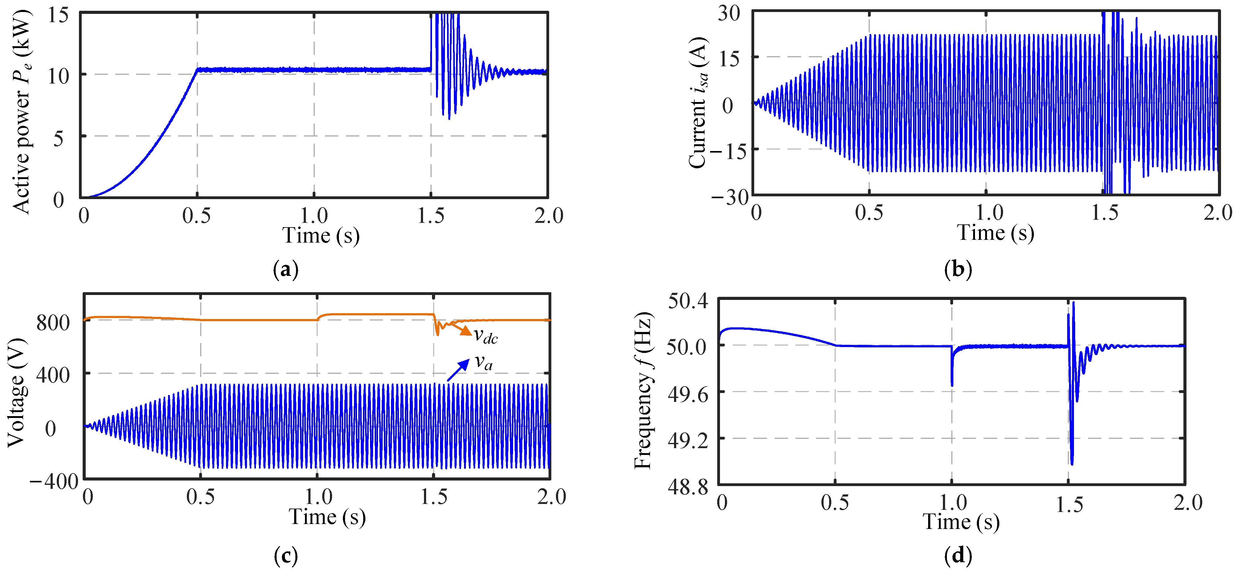
4. Simulation Results

To validate the proposed SOC-frequency control strategy, simulations were conducted under varying frequency and load conditions in a system with the rated power of 25 kW. During normal operation, the system load consumes 10 kW of active power. The main control parameters are summarized in Table 2. In order to verify the effectiveness and the impact on system performance of the proposed strategy, simulation analysis was conducted under two different scenarios and compared with the scenario without the SOC-frequency control strategy. Simulation results are shown in Figure 5, Figure 6, Figure 7 and Figure 8.

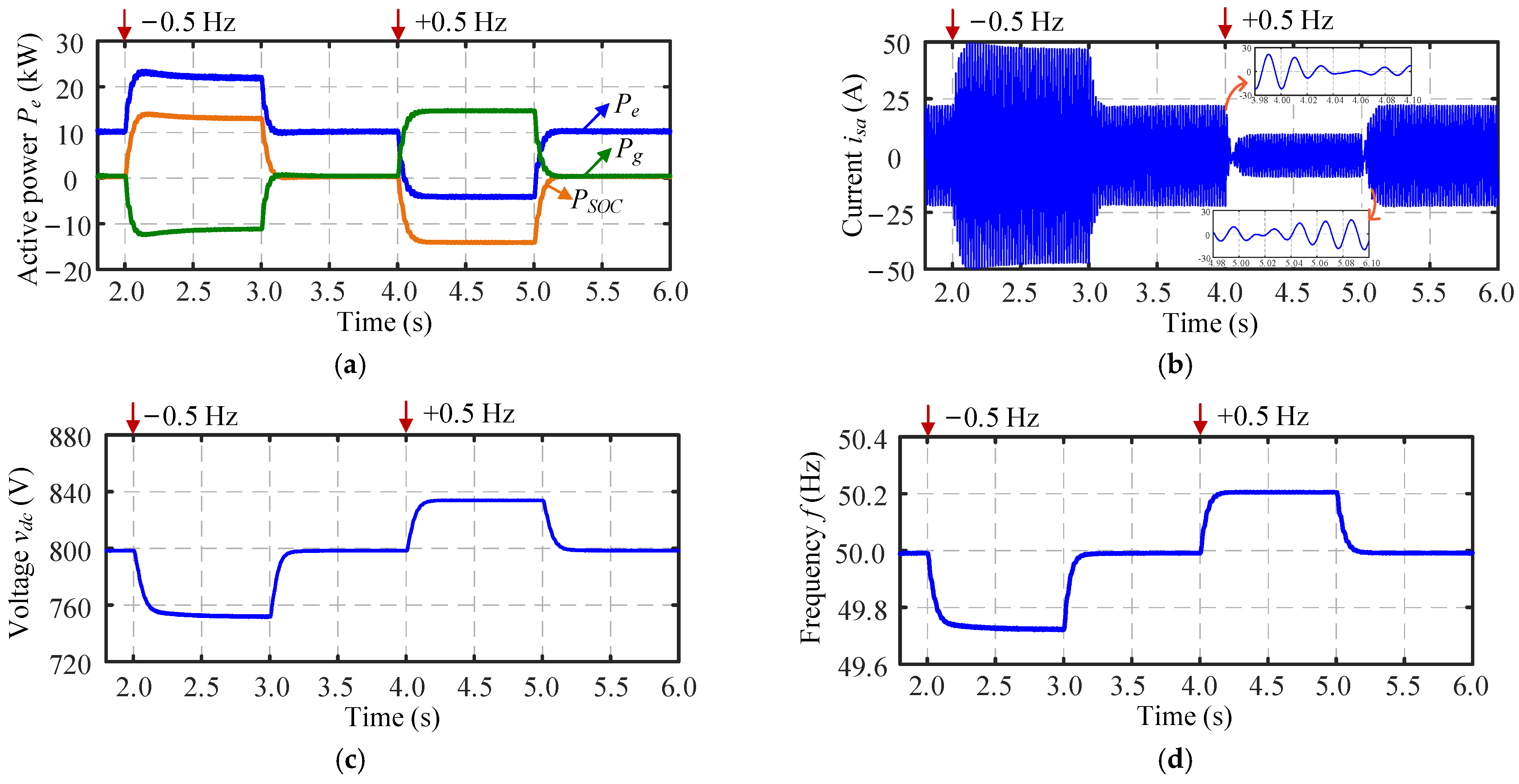
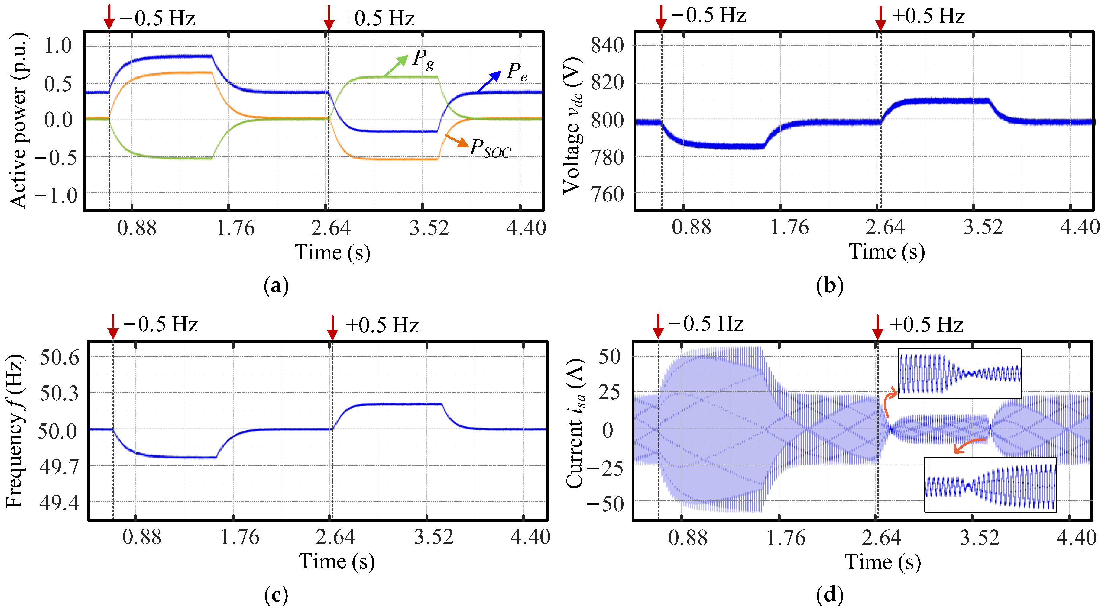
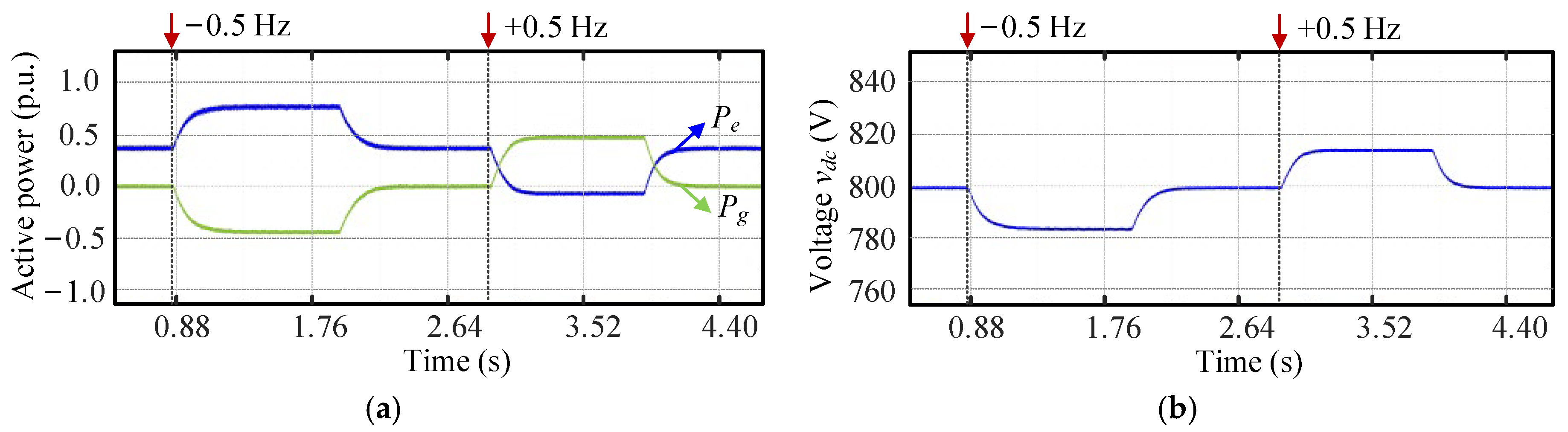
4.1. 0.5-Hz Frequency Change

At t = 1.5 s, referring to Figure 1, switch S3 was closed to enable grid-connection. At t = 2.0 s, a 0.5-Hz frequency change occurred on the grid, and the grid side frequency restored to 50 Hz at t = 3.0 s. At t = 4.0 s, a 0.5-Hz frequency change occurred, and at t = 5.0 s the grid side frequency restored again. In this case, the system response is shown in Figure 5, while Figure 6 illustrates the comparative simulation results.
When the grid-side frequency dropped, the output power of the BESS Pe increased to approximately 22 kW, as shown in Figure 5a, while the surplus active power was absorbed by the grid. This additional power output was almost entirely attributed to the SOC-frequency control, i.e., PSOC. Consequently, the inductor current isa experienced a corresponding increase, which is shown in Figure 5b. In the steady state, the DC-link capacitor voltage vdc in Figure 5c exhibits a drop of approximately 50 V and the frequency f in Figure 5d settled at 49.72 Hz. When the grid-side frequency changed to 50.5 Hz, the BESS in Figure 5a began to absorb active power, and its variation trend remained consistent with that of PSOC. As shown in Figure 5b, the current isa correspondingly decreased, and in Figure 5c, the DC-link voltage exhibits a steady-state offset of around 35 V. The frequency in Figure 5d stabilized at approximately 50.2 Hz. Meanwhile, by observing the transients at t = 4.0 and 5.0 s, a clear phase reversal of isa occurs at these two instants, revealing the switching process between charging and discharging of the energy-storage battery. Compared to the response shown in Figure 6, the model employing the proposed SOC-frequency control demonstrates strengthened damping and virtual inertia under both frequency drop and increase events, with smaller steady-state deviations. The dynamics of the frequency and active power shows the support of enhanced damping and virtual inertia by the proposed method. In addition, the battery charging and discharging process can be flexibly regulated based on frequency events, enabling coordinated energy management and frequency support.

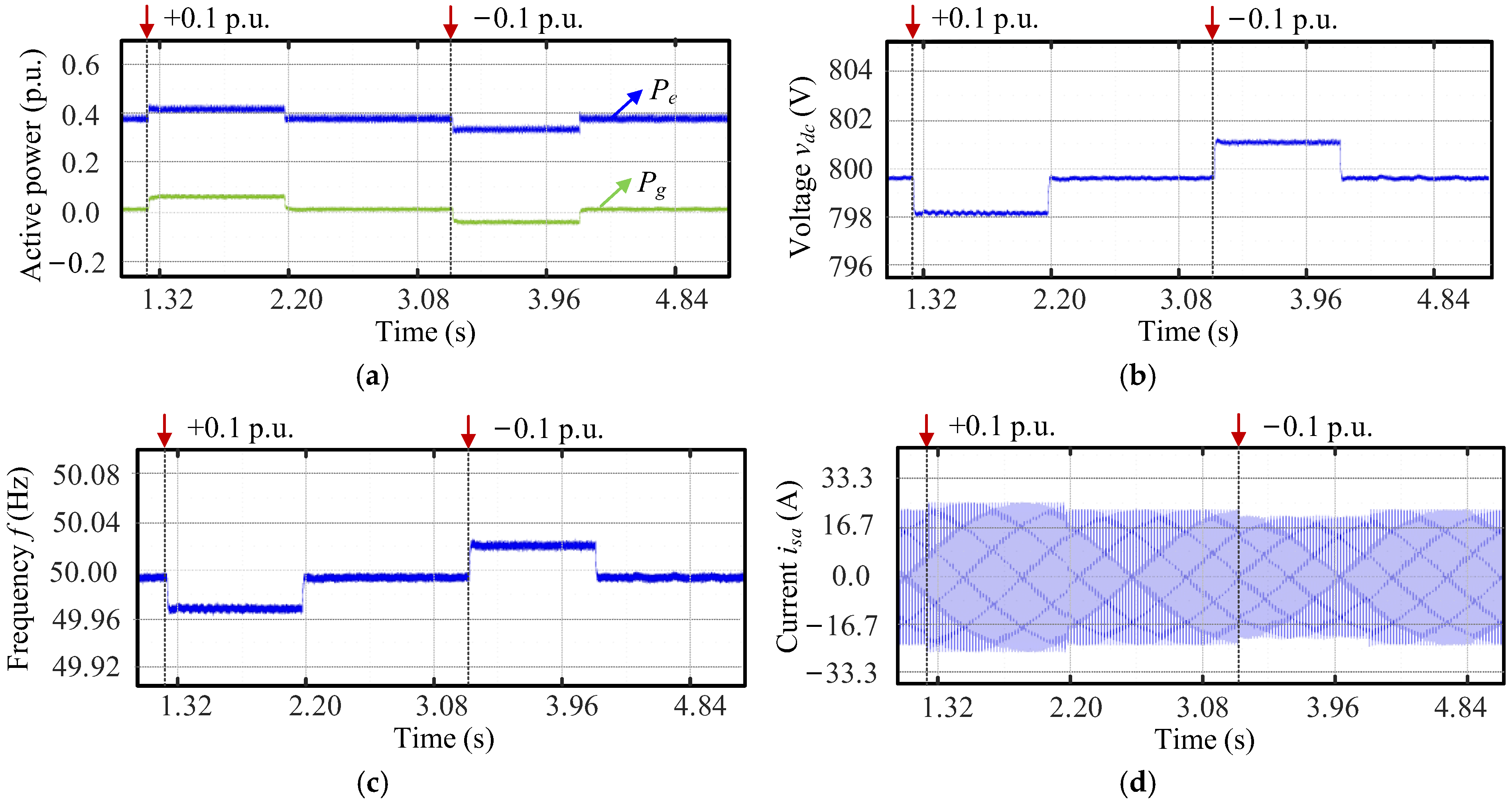
4.2. 10% Power Change

When the load increased by 10% of the rated power, i.e., 2.5 kW, Figure 7a shows that both the inverter and the grid jointly increased their power output, and the inverter current in Figure 7b increased slightly. Given that the variation trend of PSOC closely matches that of Pe, this adjustment is primarily attributed to the SOC-frequency control component. In Figure 7c,d, the DC-link voltage and system frequency experienced minor transients before settling, with relatively small overall deviations. When the load power decreased by 2.5 kW, a similar dynamic process occurred. The active power Pe, current isa, DC-link voltage vdc, and frequency f all reached steady-state values within a short period, showing the virtual inertia response of the BESS. Compared to the case without SOC-frequency control shown in Figure 8, the results in Figure 7 exhibits significantly reduced overshoots, slower variations, and smaller steady-state values that more closely approached the nominal levels. This demonstrates the effectiveness of the proposed control in enhancing both transient stability and steady state accuracy.

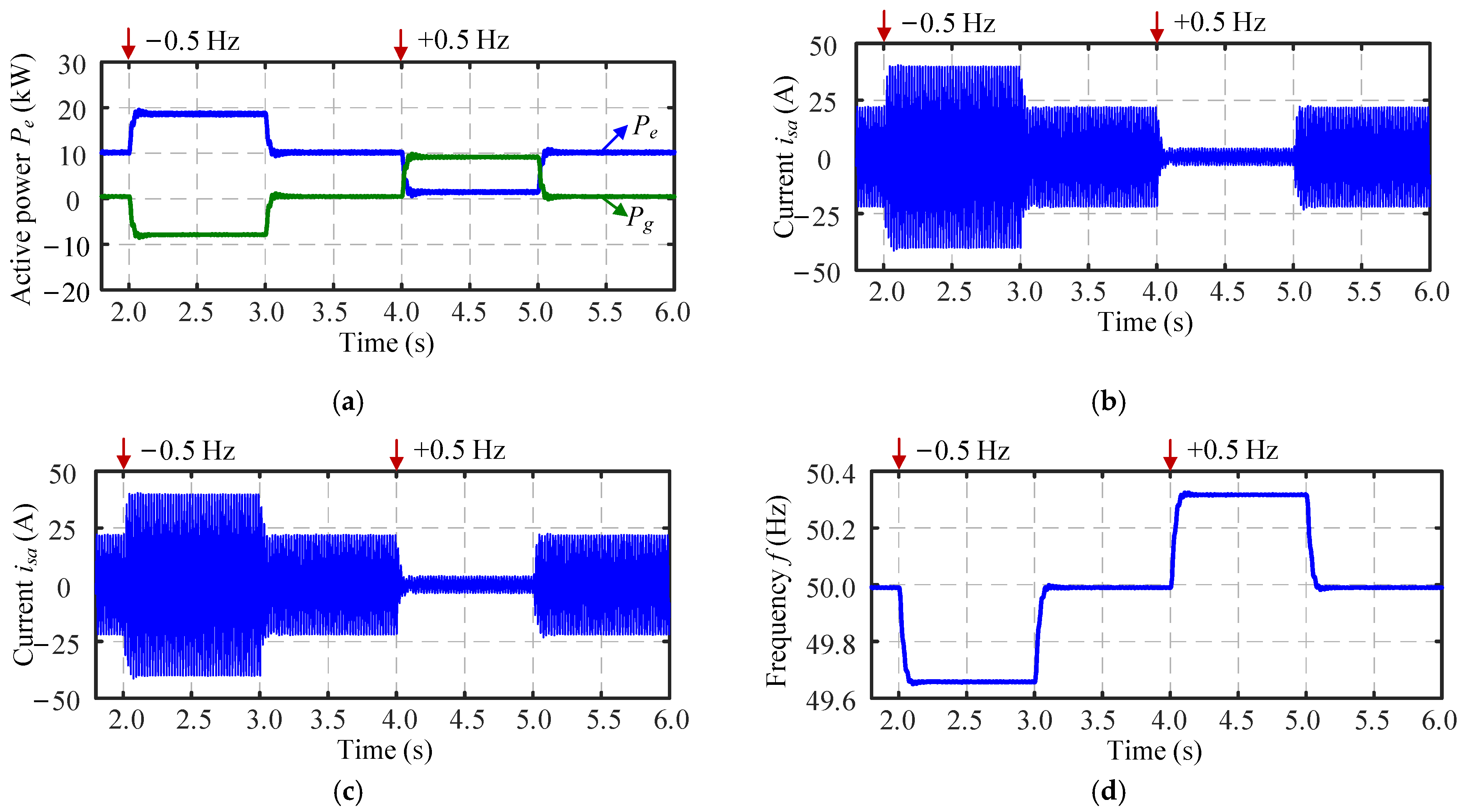
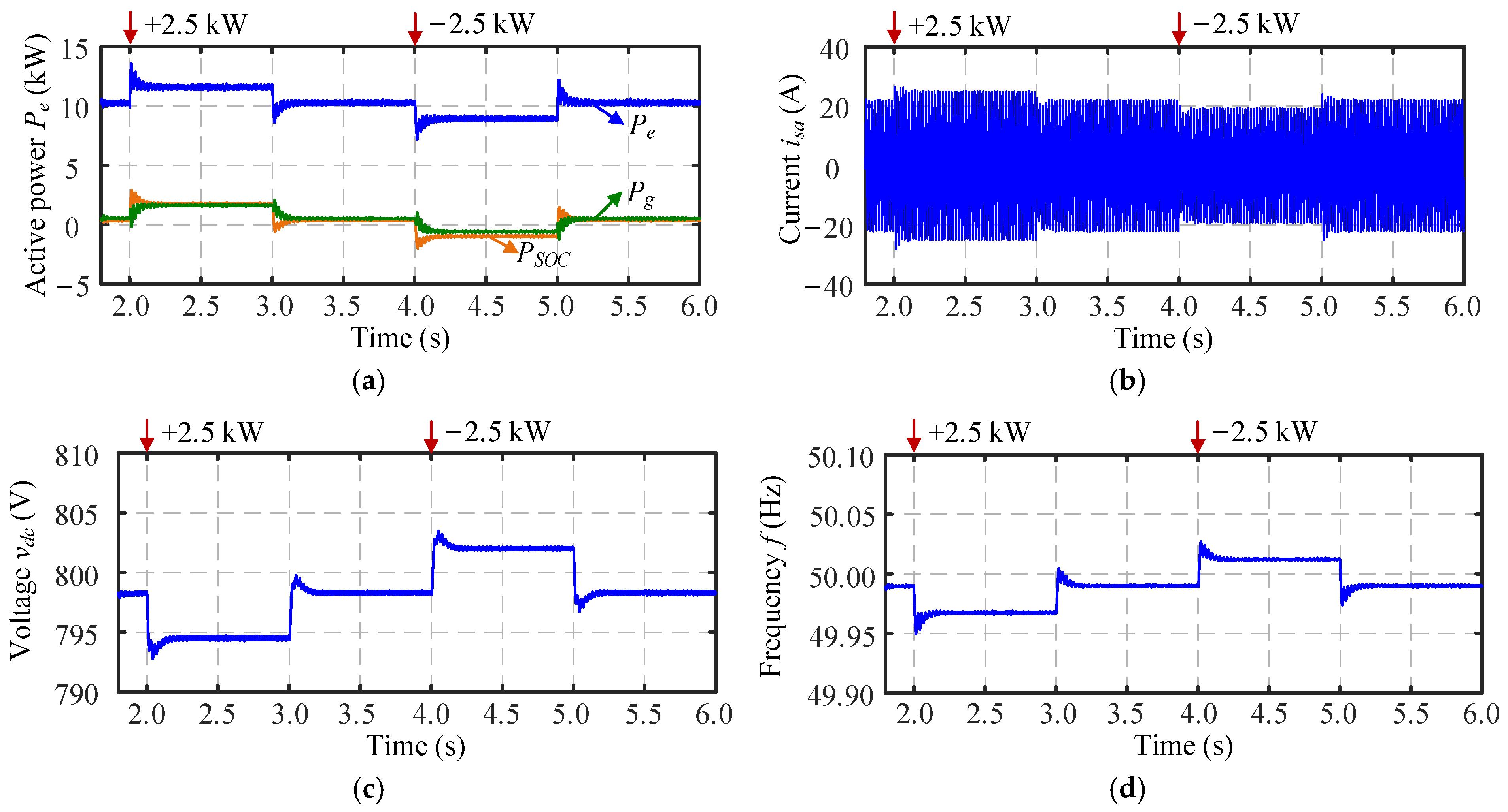
5. Experimental Validation

Experimental tests were then conducted on a hardware-in-the-loop (HIL) platform using an MT8020 real-time simulator. The system model is implemented in the FPGA of the MT8020, while the host personal computer (PC) converts the model into code and imports it into the MT8020’s built-in CPU for execution. The load power was set at 10 kW during the experiments. To modify the frequency reference value, a VSG-emulated grid was employed. The HIL experimental platform is shown in Figure 9. Similarly, two cases were conducted, and the experimental results are shown in Figure 10 and Figure 11.

5.1. 0.5-Hz Frequency Change

After the BESS is successfully connected to the grid and enters the steady state, frequency change of 0.5 Hz was applied on the grid side, and the test results are shown in Figure 10. As illustrated in Figure 10a, the output active power of the inverter Pe increased by approximately 0.5 p.u. Since the variation trend is consistent with PSOC, the power variation primarily results from the SOC-frequency control loop. The grid output power Pe decreases from 0 to −0.5 p.u. The DC-link voltage vdc in Figure 10b and the inverter frequency f in Figure 10c stabilized rapidly at 790 V and 49.8 Hz, respectively. As shown in Figure 10d, the current isa increased with the rise in Pe. When the grid-side frequency increased by 0.5 Hz, the BESS was automatically switched to the charging mode, and the other system variables exhibited changes in the opposite direction compared to the previous scenario. The phase-reversal phenomenon was also observed in Figure 10d, which fully corroborates the transition between the battery’s charging and discharging modes. In comparison with the results without the proposed method in Figure 11, Figure 10 demonstrated a stronger recovery capability under the same frequency disturbance, with smoother dynamic transitions. During this process, through the SOC-frequency control, the charging and discharging behavior of the BESS was effectively regulated, enabling flexible adaptation to variations in grid regulation requirements.

5.2. 10% Power Change

Similarly, when the active power demand increased by 0.1 p.u., the system exhibited a response pattern analogous to that observed during the frequency event. The BESS promptly increased its power output to compensate for the load disturbance, leading to a slight rise in inverter current the isa and a temporary voltage drop across the DC-link capacitor. Conversely, Figure 12a shows that when the power demand decreased by 0.1 p.u., both the BESS and the grid reduced their power output simultaneously. As illustrated in Figure 12b,c, vdc and f both experienced slight increases. Similarly, the current isa depicted in Figure 12d also decreased marginally. A comparison with Figure 13 indicated that the system with the proposed control provided smoother dynamic responses and smaller steady-state errors under load power fluctuations.

6. Conclusions

This paper proposes an SOC-frequency control strategy for the GFM BESS, establishing a droop-like relationship between the battery output power and grid frequency. As such, the proposed strategy enables the BESS to autonomously adjust its output power in response to frequency variations. The effectiveness of the proposed strategy has been validated through simulations and experimental tests performed on a HIL platform under two scenarios: a 0.5-Hz frequency change and a 10% power change. The successful HIL validation represents a major strength of this work, demonstrating the practical feasibility of the proposed method beyond purely simulation-based studies. Comparative analysis confirms that the proposed method not only enables more effective regulation of the BESS charging and discharging process during grid frequency events, but also exhibits favorable dynamic performance under both frequency change and load variation. The system benefited from enhanced damping and virtual inertia support, while the steady-state errors were significantly reduced compared to the case without the proposed control. Moreover, the proposed strategy simultaneously achieves frequency regulation and implicit energy management, representing a novel dual benefit for sustainable grid operation and long-duration black start processes.
Although the proposed control strategy shows promising results, it has several limitations. The dynamic interactions between the DC/DC and DC/AC stages have not been deeply investigated, and the validation is currently limited to a HIL platform. Future work will focus on extending the method to large-scale GFM applications and improving its physics-informed modeling, considering the challenges and integration pathways discussed in De Carne et al. [27].

Author Contributions

Methodology, validation, investigation, writing—original draft preparation, Y.Y. (Yunuo Yuan); Conceptualization, writing—review and editing, Y.Y. (Yongheng Yang). All authors have read and agreed to the published version of the manuscript.

Funding

This research was funded by a project supported by Scientific Research Fund of Zhejiang University (Project No. XY2024017) and Zhejiang Provincial Key R&D Program (No. 2024C01242(SD2)).

Data Availability Statement

The original contributions presented in the study are included in the article, further inquiries can be directed to the corresponding author.

Conflicts of Interest

The authors declare no conflicts of interest.

References

  1. Meng, L. Fast Frequency Response from Energy Storage Systems—A Review of Grid Standards, Projects and Technical Issues. IEEE Trans. Smart Grid 2020, 11, 1566–1581. [Google Scholar] [CrossRef]
  2. Smith, C.; Gargoom, A.; Arif, M.T.; Haque, M.E. Control Techniques for Grid Forming Inverters: A Comparative Analysis. In Proceedings of the 2022 IEEE Industry Applications Society Annual Meeting (IAS), Detroit, MI, USA, 9–14 October 2022; IEEE: Piscataway, NJ, USA, 2022; pp. 1–9. [Google Scholar]
  3. Li, Y.; Gu, Y.; Green, T.C. Revisiting Grid-Forming and Grid-Following Inverters: A Duality Theory. IEEE Trans. Power Syst. 2022, 37, 4541–4554. [Google Scholar] [CrossRef]
  4. Liu, L.; Wu, J.; Mi, Z.; Sun, C. A feasibility study of applying storage-based wind farm as black-start power source in local power grid. In Proceedings of the 2016 International Conference on Smart Grid and Clean Energy Technologies (ICSGCE), Chengdu, China, 19–22 October 2016; IEEE: Piscataway, NJ, USA, 2016; pp. 257–261. [Google Scholar]
  5. Rodriguez-Amenedo, J.L.; Montilla-DJesus, M.E.; Arnaltes, S.; Arredondo, F. RMS Modeling and Control of a Grid-Forming E-STATCOM for Power System Stability in Isolated Grids. Appl. Sci. 2025, 15, 3014. [Google Scholar] [CrossRef]
  6. Zhou, Z.; Pugliese, S.; Langwasser, M.; Liserre, M. Subsynchronous Damping by Battery Storage System in Grid-Forming Control. IEEE Trans. Power Electron. 2024, 39, 4173–4186. [Google Scholar] [CrossRef]
  7. Khalid, A.; Stevenson, A.; Sarwat, A.I. Overview of Technical Specifications for Grid-Connected Microgrid Battery Energy Storage Systems. IEEE Access 2021, 9, 163554–163593. [Google Scholar] [CrossRef]
  8. Antunes, H.M.A.; Silva, S.M.; Brandao, D.I.; Machado, A.A.P.; Ferreira, R.V. A fault-tolerant grid-forming converter applied to AC microgrids. Int. J. Electr. Power Energy Syst. 2020, 121, 106072. [Google Scholar] [CrossRef]
  9. Pattabiraman, D.; Lasseter, R.H.; Jahns, T.M. Comparison of Grid Following and Grid Forming Control for a High Inverter Penetration Power System. In Proceedings of the 2018 IEEE Power & Energy Society General Meeting (PESGM), Portland, OR, USA, 5–10 August 2018; IEEE: Piscataway, NJ, USA, 2018; pp. 1–5. [Google Scholar]
  10. Wang, H.; Wang, H. Black Start Scheme of Wind-storage Combined System Based on Virtual Synchronous Generator Control. In Proceedings of the 2023 2nd Asia Conference on Electrical, Power and Computer Engineering (EPCE), Xiamen, China, 22–24 April 2023; IEEE: Piscataway, NJ, USA, 2023; pp. 60–64. [Google Scholar]
  11. Noris, L.; Rueda, J.L.; Rakhshani, E.; Korai, A.W. Power System Black-Start and Restoration with High Share of Power-Electronic Converters. In Proceedings of the 2019 IEEE Power & Energy Society General Meeting (PESGM), Atlanta, GA, USA, 4–8 August 2019; IEEE: Piscataway, NJ, USA, 2019; pp. 1–5. [Google Scholar]
  12. Pagnani, D.; Kocewiak, L.; Hjerrild, J.; Blaabjerg, F.; Bak, C.L.; Blasco-Gimenez, R.; Martínez-Turégano, J. Power System Restoration Services by Grid-Forming Offshore Wind Farms with Integrated Energy Storage. In Proceedings of the 2023 IEEE Power & Energy Society General Meeting (PESGM), Orlando, FL, USA, 16–20 July 2023; IEEE: Piscataway, NJ, USA, 2023; pp. 1–5. [Google Scholar]
  13. Chaudhary, S.K.; Teodorescu, R.; Svensson, J.R.; Kocewiak, L.H.; Johnson, P.; Berggren, B. Black Start Service from Offshore Wind Power Plant using IBESS. In Proceedings of the 2021 IEEE Madrid PowerTech, Madrid, Spain, 27 June–2 July 2021; IEEE: Piscataway, NJ, USA, 2021; pp. 1–6. [Google Scholar]
  14. Tang, X.; Qi, Z. Energy storage control in renewable energy based microgrid. In Proceedings of the 2012 IEEE Power and Energy Society General Meeting, San Diego, CA, USA, 22–26 July 2012; IEEE: Piscataway, NJ, USA, 2012; pp. 1–6. [Google Scholar]
  15. Burroughs, H.; Klauber, C.; Sun, C.-C.; Culler, M. Black Start with Inverter-Based Resources: Hardware Testing. In Proceedings of the 2023 IEEE Power & Energy Society General Meeting (PESGM), Orlando, FL, USA, 27–31 July 2023; IEEE: Piscataway, NJ, USA, 2023; pp. 1–5. [Google Scholar]
  16. Zhao, Y.; Liu, S.; Han, Y.; Yang, T.; Zhao, A. Practical Verification and Analysis of Grid-Forming Energy Storage Technology based on Black Start Testing of Pure New Energy Sources. In Proceedings of the 2024 International Conference on New Power System and Power Electronics (NPSPE), Dalian, China, 16–18 August 2024; IEEE: Piscataway, NJ, USA, 2024; pp. 60–68. [Google Scholar]
  17. Jing, Z.; Zhang, H.; Yang, P. Research on control system of new energy storage combined thermal power unit based on improved voltage droop control. In Proceedings of the 2024 6th International Conference on Intelligent Control, Measurement and Signal Processing (ICMSP), Xi’an, China, 29 November–1 December 2024; IEEE: Piscataway, NJ, USA, 2024; pp. 16–21. [Google Scholar]
  18. Zhang, Z.; Zhang, H.; Gong, X.; Cheng, X.; Zhou, S.; Yu, H. Research on the Control Strategy for Black Start of Power Grid with Large-Capacity Energy Storage. In Proceedings of the 2020 12th IEEE PES Asia-Pacific Power and Energy Engineering Conference (APPEEC), Nanjing, China, 20–23 September 2020; IEEE: Piscataway, NJ, USA, 2020; pp. 1–5. [Google Scholar]
  19. Shahparasti, M.; Kauhaniemi, K.; Lauttamus, P.; Strandberg, S.; Strandberg, J. Inrush Current Management During Medium Voltage Microgrid Black Start with Battery Energy Storage System. IEEE Access 2022, 10, 42287–42296. [Google Scholar] [CrossRef]
  20. Li, J.; You, H.; Qi, J.; Kong, M.; Zhang, S.; Zhang, H. Stratified Optimization Strategy Used for Restoration with Photovoltaic-Battery Energy Storage Systems as Black-Start Resources. IEEE Access 2019, 7, 127339–127352. [Google Scholar] [CrossRef]
  21. Xia, L.; Zhang, M.; Ma, S.; Zhuang, G.; Yu, K. Analysis of the Soft-Start Circuit of the High Voltage Power Supply Based on PSM Technology. IEEE Trans. Plasma Sci. 2014, 42, 1026–1031. [Google Scholar] [CrossRef]
  22. Wu, J.; Zhuo, F.; Wang, Z.; Yi, H.; Yu, K. Pre-synchronization method for grid-connection of virtual synchronous generators based micro-grids. In Proceedings of the 2017 19th European Conference on Power Electronics and Applications (EPE’17 ECCE Europe), Warsaw, Poland, 11–14 September 2017; IEEE: Piscataway, NJ, USA, 2017; pp. P.1–P.8. [Google Scholar]
  23. Huang, L.; Xin, H.; Wang, Z.; Wu, K.; Wang, H.; Hu, J.; Lu, C. A Virtual Synchronous Control for Voltage-Source Converters Utilizing Dynamics of DC-Link Capacitor to Realize Self-Synchronization. IEEE J. Emerg. Sel. Top. Power Electron. 2017, 5, 1565–1577. [Google Scholar] [CrossRef]
  24. Ai, C.; Li, Y.; Zhao, Z.; Gu, Y.; Liu, J. An Extension of Grid-Forming: A Frequency-Following Voltage-Forming Inverter. IEEE Trans. Power Electron. 2024, 39, 12118–12123. [Google Scholar] [CrossRef]
  25. Li, S.; Li, J.; Mo, Y. Piezoelectric Multimode Vibration Control for Stiffened Plate Using ADRC-Based Acceleration Compensation. IEEE Trans. Ind. Electron. 2014, 61, 6892–6902. [Google Scholar] [CrossRef]
  26. Dabroom, A.; Khalil, H.K. Numerical differentiation using high-gain observers. In Proceedings of the 36th IEEE Conference on Decision and Control, San Diego, CA, USA, 12 December 1997; IEEE: Piscataway, NJ, USA, 1997; pp. 4790–4795. [Google Scholar]
  27. De Carne, G.; Maroufi, S.M.; Beiranvand, H. The role of energy storage systems for a secure energy supply: A comprehensive review of system needs and technology solutions. Electr. Power Syst. Res. 2024, 236, 110963. [Google Scholar] [CrossRef]
Figure 1. System model for the GFM BESS in the black-start scenario, where PCC stands for the point of common coupling, the VSG control is adopted for the grid inverter, and SPWM represents the sinusoidal pulse width modulation.
Batteries 11 00296 g001
Figure 2. Simulation results of the system in Figure 1 in black start operation: (a) active power Pe, (b) phase-a current isa, (c) DC-link voltage vdc and the phase-a voltage va, and (d) frequency f.
Batteries 11 00296 g002
Figure 3. Control structure of the proposed scheme for the grid-connected BESS.
Batteries 11 00296 g003
Figure 4. Dual Closed-loop control structure following the matching control.
Batteries 11 00296 g004
Figure 5. Simulation results of the inverter with the proposed method under the 0.5-Hz frequency change: (a) active power Pe, (b) phase-a current isa, (c) DC-link voltage vdc, and (d) frequency f.
Batteries 11 00296 g005
Figure 6. Comparative simulation results of the inverter without the proposed method under the 0.5-Hz frequency change: (a) active power Pe, (b) phase-a current isa, (c) DC-link voltage vdc, and (d) frequency f.
Batteries 11 00296 g006
Figure 7. Simulation results of the inverter with the proposed method under the 10% power change: (a) active power Pe, (b) phase-a current isa, (c) DC-link voltage vdc, and (d) frequency f.
Batteries 11 00296 g007
Figure 8. Comparative simulation results of the inverter without the proposed method under the 10% power change: (a) active power Pe, (b) phase-a current isa, (c) DC-link voltage vdc, and (d) frequency f.
Batteries 11 00296 g008
Figure 9. Experimental platform of the HIL system for the BESS with the SOC-frequency control.
Batteries 11 00296 g009
Figure 10. HIL experimental test results of the inverter with the proposed method under the 0.5-Hz frequency change: (a) active power, (b) DC-link voltage vdc, (c) frequency f, and (d) phase-a current isa.
Batteries 11 00296 g010
Figure 11. Comparative HIL experimental test results of the inverter without the proposed method under the 0.5-Hz frequency change: (a) active power, (b) DC-link voltage vdc, (c) frequency f, and (d) phase-a current isa.
Batteries 11 00296 g011aBatteries 11 00296 g011b
Figure 12. HIL experimental test results of the inverter with the proposed method under the 10% power change: (a) active power, (b) DC-link voltage vdc, (c) frequency f, and (d) phase-a current isa.
Batteries 11 00296 g012
Figure 13. Comparative HIL experimental test results of the inverter without the proposed method under the 10% power change: (a) active power, (b) DC-link voltage vdc, (c) frequency f, and (d) phase-a current isa.
Batteries 11 00296 g013
Table 1. Key parameters of the system in Figure 1 for black start.
ParameterValueParameterValue
Lf, Lfg3 mHRf, Rfg0.1 Ω
Cf, Cfg10 µFRd, Rdg1.2 Ω
Lg1.5 mHRg0.1 Ω
Vdc800 Vwn, wgref314 rad/s
Table 2. Control parameters of the system referring to Figure 1.
ParameterValueParameterValue
vdcref800 VKT70 V2·F·J−1
KJ15,700 kg·m2·F−1KD3.0 × 106 J·rad−1·F−1
Kq0.0031 APset10 kW
ks0.00148 s−1En5 V·Ah
K0.02 s−1·Hz−1Pgref0 kW
Qgref0 kVarVref311 V
a12a21
ε5.0 × 10⁻⁵Ts1.0 × 10−4 s
Disclaimer/Publisher’s Note: The statements, opinions and data contained in all publications are solely those of the individual author(s) and contributor(s) and not of MDPI and/or the editor(s). MDPI and/or the editor(s) disclaim responsibility for any injury to people or property resulting from any ideas, methods, instructions or products referred to in the content.

