Article

Performance of Low-Cost Energy Dense Mixed Material MnO2-Cu2O Cathodes for Commercially Scalable Aqueous Zinc Batteries

1
Urban Electric Power Inc., 401 North Middletown Road, Pearl River, NY 10965, USA
2
The Energy Institute, The City College of New York, 160 Convent Avenue, New York, NY 10031, USA
3
Sandia National Laboratories, Department of Photovoltaics and Materials Technology, P.O. Box 5800, Albuquerque, NM 87185, USA
4
Sandia National Laboratories, Center for Integrated Nanotechnologies, P.O. Box 5800, Albuquerque, NM 87185, USA
*
Authors to whom correspondence should be addressed.
Batteries 2025, 11(8), 291; https://doi.org/10.3390/batteries11080291 (registering DOI)
Submission received: 25 May 2025 / Revised: 26 July 2025 / Accepted: 30 July 2025 / Published: 1 August 2025

Abstract

Zinc (Zn)-based batteries have attracted significant interest for applications ranging from electric bikes to grid storage because of its advantageous properties like high abundance, non-toxicity and low-cost. Zn offers a high theoretical capacity of two electrons per atom, resulting in 820 mAh/g, making it a promising anode material for the development of highly energy dense batteries. However, the advancement of Zn-based battery systems is hindered by the limited availability of cathode materials that simultaneously offer high theoretical capacity, long-term cycling stability, and affordability. In this work, we present a new mixed material cathode system, comprising of a mixture of manganese dioxide (MnO2) and copper oxide (Cu2O) as active materials, that delivers a high theoretical capacity of ~280 mAh/g (MnO2 + Cu2O active material) (based on the combined mass of MnO2 and Cu2O) and supports stable cycling for >200 cycles at 1C. We further demonstrate the scalability of this novel cathode system by increasing the electrode size and capacity, highlighting its potential for practical and commercial applications.

1. Introduction

Research on zinc (Zn)-anode batteries has recently attracted significant attention due to their potential across a broad range of applications, from high power to high energy density systems [1,2,3,4]. The performance of such batteries is largely governed by the characteristics of the electrodes and electrolytes, which directly impact both energy and power densities. Zn anodes exhibit a high theoretical capacity of 820 mAh/g, based on a two-electron conversion process involving a reversible dissolution–precipitation reaction [1,2,3,4,5]. This enables Zn-based systems to achieve both high power and energy densities. Moreover, Zn can operate electrochemically in both aqueous and non-aqueous electrolytes. Given the focus of this work on environmentally friendly and cost-effective battery technologies, we restrict our discussion to aqueous electrolytes.
Within aqueous systems, prior research has investigated acidic, neutral, and alkaline electrolytes [6,7,8]. Alkaline electrolytes, such as sodium hydroxide (NaOH) and potassium hydroxide (KOH), offer significantly higher ionic conductivities (>200–300 mS cm−1) compared to their neutral and acidic counterparts, which is critical for achieving high power densities [9]. Notably, these high ionic conductivities can also be realized in gelled alkaline electrolytes, paving the way for the development of solid-state Zn-anode batteries [1,10,11]. To fully exploit the advantages of Zn anodes, cathode materials with comparable characteristics—namely high capacity, rate capability, and stability—are essential for achieving high overall battery performance.
Alkaline Zn-anode batteries currently lack cathode materials that are simultaneously stable, low-cost, non-toxic, and capable of delivering high capacities. For indicative purposes, some typical cathodes for zinc anodes are indicated in Table 1 that shows a comparison of capacity and cost estimates per kilowatt hour under the conditions assuming the first electron discharge capacity. Prices are based on current day estimates, larger price fluctuations can change due to external factors. In any case, manganese dioxide and copper are of interest due as lower cost as solid cathodic materials as well as bromine compounds which are used in flow batteries.
While cathodes such as silver oxide and nickel oxyhydroxide offer relatively high capacities, they are prohibitively expensive for grid storage applications. Moreover, nickel oxyhydroxide often contains cobalt additives to enhance rate performance, which increases both cost and toxicity. Manganese dioxide (MnO2), a more abundant and less toxic alternative, typically suffers from poor rechargeability. To mitigate this, MnO2 is often cycled at limited utilization (10–20%) of its high theoretical capacity (617 mAh/g) [12,13,14,15,16,17,18,19]. though this approach compromises the overall energy density of the battery.
Recent strategies have focused on improving the reversibility of MnO2-based cathodes [20,21]. For example, intercalating copper (Cu2+) ions into layered birnessite—a polymorph of MnO2—has enabled regenerable cathodes with reversible two-electron capacity equivalent retention for over more than 6000 cycles [22,23,24]. Cu2+ ions are intercalated between the interlayers of Bi-δ-MnO2 during charge and reduced to Cu0 with an Mn(OH)2 layered material when discharged. The addition of copper has shown to greatly improve the charge–transfer characteristics of MnO2, preventing unwanted and irreversible compounds from forming, and allowing it to achieve the 2-electron capacity of MnO2 [25].
However, these systems typically rely on expensive components such as carbon nanotubes and binder-free electrode architectures, posing significant challenges for large-scale manufacturing and adaptability across different battery form factors. Others have investigated Cu-MnO2 for supercapacitors [26,27] and as cathodes in mildly acidic electrolytes [28,29,30] for zinc-ion batteries, but there is little published work on Cu-MnO2 using alkaline electrolytes.
For practical and commercial viability, cathodes must not only deliver high capacities across a range of C-rates but also be compatible with conventional manufacturing meth-ods and formats (e.g., cylindrical or prismatic cells). Additionally, they must be cost-effective with an eventual goal to drive down cost of Zn-MnO2 to ~$50/kWh [31] while being environmentally benign to support widespread deployment.
In this manuscript, we report a mixed material cathode design that combines two electroactive materials—manganese dioxide (MnO2) and copper oxide (Cu2O)—to enable stable, high-capacity performance in alkaline Zn-anode batteries. Both MnO2 and Cu-based materials are low-cost, non-toxic, and possess high theoretical capacities: 617 mAh/g for MnO2 and approximately 376 mAh/g for Cu2O, each based on two-electron redox reactions [32]. However, the extent to which these theoretical capacities can be accessed depends strongly on the battery’s cycling voltage range [33]. For instance, at a minimum cutoff voltage of 0.8 V vs. Zn, MnO2 typically delivers ~308 mAh/g, primarily corresponding to a one-electron process. Most of the capacity of the copper oxide (Cu2O) discharge lies below 0.8 V [32,34,35] so narrowing the voltage window restricts the number of copper electrons accessed during cycling. More work needs to be completed in order to understand the capacity percentage contribution from MnO2, Cu2O, and Bi2O3 when the battery is being cycled at given voltage ranges.
In our system, we have successfully paired MnO2 and Cu-based materials to achieve a reversible capacity of ~280 mAh/g (based on the combined mass of both electroactive components (MnO2 + Cu2O) when cycled above 0.8 V vs. Zn). This mixed material cathode of MnO2 and Cu2O exhibits excellent cycling stability with no observable capacity fade over 200 cycles. In addition, we demonstrate the scalability of this design by increasing electrode capacity, evaluating the performance in a cylindrical cell format, and presenting a preliminary cost analysis of a mixed material Zn|MnO2–Cu battery.

2. Experimental Section

  • Materials: Electrolytic manganese dioxide (EMD) was purchased from Borman (Las Vegas, NV, USA). Zinc (Zn) powders were purchased from Grillo-Werke AG (Duisburg, Germany). Potassium hydroxide (KOH) was purchased from Fisher Scientific (Waltham, MA, USA). Graphite (MX-25 and BNB-90) was purchased from Imerys Graphite & Carbon (Terrebonne, QC, Canada, previously known as TIMCAL). Carbon nanotubes (CNTs) were purchased from CNano (Reno, NV, USA). Bismuth oxide (Bi2O3), copper oxide (Cu2O) powder was purchased from Sigma-Aldrich (St. Louis, MO, USA). Nickel and copper mesh were purchased from PPG Engineered Materials (Wallingford, CT, USA, formerly known as Dexmet Corporation). Dispersion Teflon was purchased from DuPont (Wilmington, DE, USA). Sintered nickel electrodes were purchased from Jiangsu HighStar Battery Manufacturing (Qidong, China). Cellophane was purchased from Innovia Films (Wigton, UK). Pellon was purchased from Freudenberg (Weinheim, Germany). Crosslinked polyvinyl alcohol (PVA) separators were made in-house by casting a water solution of 5–10wt.% PVA [36].
  • Electrode Fabrication: Electrodes were made by first mixing the raw materials with dispersion Teflon into a homogenous mixture and rolled into sheets using a rolling pin or a rolling machine. These sheets were dried at 60 °C overnight. The dried sheets were then pressed onto current collectors. Cathode sheets were pressed onto nickel mesh while anode sheets were pressed onto copper mesh.
    The cathodes were composed of 29 wt.% EMD, 35 wt.% Cu2O, 23 wt.% graphite or carbon nanotubes 10 wt.% Bi2O3 and 3 wt.% Teflon, while the anodes were composed of 97 wt.% Zn and 3 wt.% Teflon. These compositions remained the same for prismatic or cylindrical form factor cells. Zn electrodes were only used in “full cells” when cathode performance vs. Zn anodes needed to be tested. In “half-cell” tests, we used a sintered nickel counter electrode and a mercury (Hg)|mercury oxide (HgO) reference electrode to test only the cathode performance.
    The fabricated electrodes size changed with the type of experiment performed. Usually, the prismatic electrode sizes were 2 in × 3 in and 3 in × 6 in while cylindrical electrode sizes ranged from 3 in × 12 in to 3 in × 17 in.
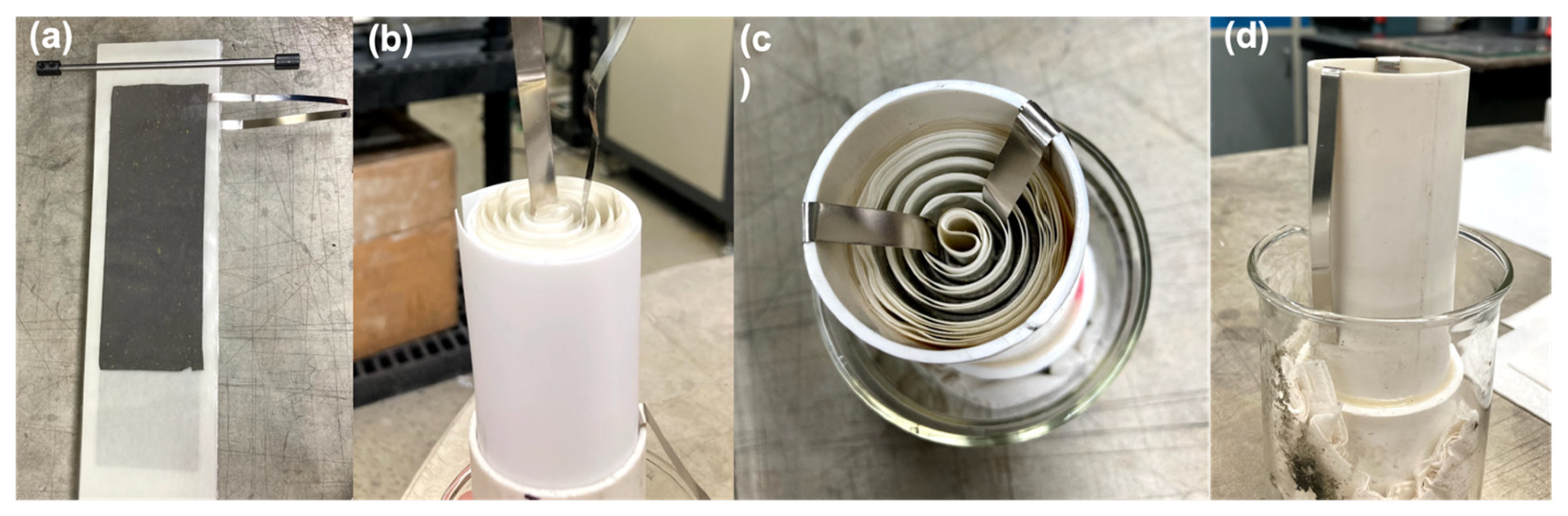
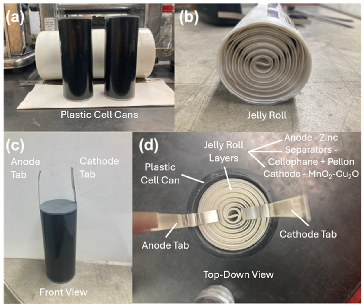
  • Battery Fabrication: Prismatic and cylindrical form factor cells were tested. Prismatic cells were conducted in polysulfone boxes whose dimensions were 3.26 in × 2.23 in × 6.25 in (width × depth × height). Electrode packs consisting of anodes and cathodes were wrapped in one or two layers of cellophane (0.001 in each layer) or crosslinked polyvinyl alcohol (PVA) (0.002 ± 0.001 in) separator. We also used 3.44 in × 1.85 in × 8.13 in (width × depth × height) polypropylene boxes for testing larger electrodes. These packs were compressed in prismatic cell boxes between polypropylene shims. The shims were placed on each side of the multiple electrode pack. Prismatic and cylindrical cells were filled with either 25 or 37 wt.% potassium hydroxide (KOH) electrolyte as noted.
    PVC pipes (purchased from McMaster Carr, Elmhurst, IL, USA) were used for cylindrical can designs. The pipe outer diameter was 2 in and the inner diameter was 1.6 in. The pipes were cut to different heights for different cell capacity testing. The cylindrical electrodes were rolled with the help of a rolling pin to obtain the right alignment. The electrodes were separated by cellophane and Pellon.
  • Battery Testing and Equipment: A multi-channel ARBIN BT-2000 (College Station, TX, USA) and PEC tester (Leuven, Belgium) were used for cycling the cells. Cell capacities and C-rates were determined by the amount of active material (MnO2 and Cu2O) used in the cells. Bi2O3 has a known capacity (345.11 mAh/g) but was not counted here since only a small amount was used and has a negligible capacity contribution depending on the discharge voltage cutoff used. Voltaiq was used for battery data plotting and analysis. Batteries were cycled under capacity limits or voltage limits. Capacity limits were set to 280 mAh/g active material (MnO2 + Cu2O) while the voltage limits between 0.3 V and −1.0 V vs. Hg|HgO (equivalent to ~1.65–1.7 V and ~0.35 V vs. Zn) were utilized to access to the entire active material capacity available in the cathode. For cells utilizing graphite in place of carbon nanotubes, a modified capacity-limited cycling protocol was used.

3. Results and Discussion

The first mixed material cathode was composed of copper oxide (Cu2O) powder and electrolytic manganese dioxide (EMD), a γ-MnO2 polymorph commonly used in commercial Zn–MnO2 primary batteries due to its strong discharge performance at high voltages against a Zn anode. EMD exhibits a characteristic sigmoidal discharge profile, indicative of a proton-insertion mechanism that enables access to its one-electron capacity. This behavior arises from its defect-rich tunnel structure, which facilitates proton intercalation. However, during discharge in KOH, the reduction in Mn4+ to Mn3+ leads to the dissolution of Mn ions, causing structural degradation of EMD and resulting in irreversible capacity loss.
To mitigate this issue, bismuth oxide (Bi2O3) was added to the cathode formulation. Bi2O3 acts as a complexing agent, binding with dissolved Mn ions to form Bi–Mn hydroxyl complexes that suppress the formation of electrochemically inactive spinel phases such as Mn3O4 [25,37,38]. This interaction, along with the presence of dissolved Mn, induces a structural transformation of γ-MnO2 during charging into the layered δ-MnO2 (birnessite) polymorph [39,40]. This transition is reflected in a shift of the voltage profile from a sigmoidal shape in the first cycle to a flatter discharge curve from the second cycle onward.
The mixed material cathodes exhibited distinct discharge characteristics consistent with those described previously. To evaluate their electrochemical performance and voltage profiles, we conducted half-cell tests under various C-rates and potassium hydroxide (KOH) concentrations (25 wt.% and 37 wt.%). Initial testing was performed in 25 wt.% KOH at a C/3 rate, with electrode dimensions of 2 × 3 inches, as shown in Figure 1a,b. The discharge profile displayed the characteristic sigmoidal shape associated with the first electron reduction in EMD (γ-MnO2), followed by a flatter region beyond −0.4 V vs. Hg|HgO, corresponding to the second electron reaction involving the reduction in Mn3+ to Mn2+.
The performance of the voltage-limited cycled mixed material cathode is presented in Figure 1a,b. The charge–discharge profiles under this protocol are similar in shape to those observed in the later capacity-limited tests; however, the flat voltage plateaus are noticeably extended, indicating additional electrochemical activity and deeper conversion of Cu and Mn ions. Under these 100% capacity utilization conditions, the cathode achieved a specific capacity of approximately 600 mAh/g (based on the combined mass of active materials), approaching the theoretical capacities of the individual Cu and Mn oxides.
Under these full capacity utilization tests, capacity fade was observed over extended cycling, likely due to the formation of inactive Mn oxide spinel phases, dissolution of soluble cuprate [Cu(OH)42−] species, and possible formation of electrochemically stranded (inactive) Cu2O [30,32,34]. Nevertheless, the electrode delivered a specific capacity of nearly 400 mAh/g after 160 cycles, demonstrating competitive energy density compared to more costly cathode materials such as silver oxide and nickel oxyhydroxide.
The discharge capacity 600 mAh/g of the active material can be obtained but the capacity is greatly reduced during cycling. Therefore, to assure a practical battery with low capacity fade, we limited the discharge capacity to 280 mAh/g (MnO2 + Cu2O active material). All future cells were capacity-limited to 280 mAh/g (MnO2 + Cu2O active material based on the combined active material mass), resulting in an early cutoff of the discharge curve, as seen in Figure 2a.
During charging, the discharged manganese oxide—likely a mixture of MnOOH and Mn(OH)2—is oxidized to δ-MnO2, while copper undergoes sequential oxidation to Cu2O and subsequently to CuO. Due to the capacity-limited cycling protocol, it is likely that both Mn and Cu exist in mixed oxidation states at the end of charge. From the second cycle onward, the charge–discharge profiles (Figure 2a) exhibit reproducible flat voltage plateaus, characteristic of both Mn and Cu oxides.
These flat profiles are indicative of dissolution–precipitation processes, also known as conversion reactions, for both Mn and Cu. Conversion reactions typically yield higher capacities and faster charge–transfer kinetics compared to intercalation mechanisms, leading to improved rate capability. Although such reactions can be difficult to stabilize, the inclusion of Bi2O3 in the cathode formulation helps control the redox chemistry via complexation with transition metal ions, resulting in more stable cycling, as shown in Figure 2b.
This improved performance is also maintained at higher cycling rates. At 1C (Figure 2c), the charge–discharge behavior remains comparable—or slightly improved—relative to C/3. The cells demonstrate excellent coulombic efficiency and capacity retention, maintaining near 100% efficiency over 200 cycles (Figure 2d).
The cycling performance of the mixed material cathodes was further evaluated at C/3 and 1C in 37 wt.% KOH, as shown in Figure 3a–d. The charge–discharge profiles (Figure 3a,c) at both rates closely resembled those observed in 25 wt.% KOH, which is expected given that both Mn and Cu ions are soluble in these alkaline concentrations. As shown in Figure 3b,d, the capacity retention and coulombic efficiency were improved in 37 wt.% KOH relative to 25 wt.%, likely due to enhanced solubility of Mn and Cu ions. This improved solubility may facilitate more efficient deposition during charging and dissolution during discharging, resulting in more stable cycling behavior.
The mixed material cathodes cycled under the capacity-limited protocol deliver a high capacity of 280 mAh/g (MnO2 + Cu2O active material), with discharge occurring at high voltages against Zn anodes, as shown in Figure 2 and Figure 3. To explore the maximum capacity achievable from this mixed material system, we next conducted voltage-limited cycling between 0.3 V and −1.0 V vs. Hg|HgO (equivalent to ~1.65–1.7 V and ~0.35 V vs. Zn) in 25 wt.% KOH at a C/3 rate. These voltage boundaries represent the practical electrochemical stability window of the KOH electrolyte allowing maximum access to the electrode’s capacity.
Charging beyond 0.3–0.35 V vs. Hg|HgO risks oxygen evolution and over-oxidation of Mn to Mn7+, leading to irreversible capacity loss. Similarly, discharging below −1.0 V vs. Hg|HgO can induce hydrogen evolution and offers no additional capacity, as both Cu and Mn exist in their fully reduced states—metallic Cu and Mn2+ in the form of Mn(OH)2—rendering further electrochemical reaction inactive.
The cathodes evaluated in Figure 1, Figure 2 and Figure 3 utilized carbon nanotubes (CNTs) as the conductive carbon source. While CNTs currently incur high costs due to limited production volumes, future advancements in manufacturing are expected to reduce their price, potentially bringing them in line with more economical graphite materials. To explore cost-effective alternatives, we investigated various types of graphite and identified a combination of MX-25 and BNB-90 that demonstrated comparable electrochemical performance to CNTs.
This graphite blend was incorporated into the mixed material cathode formulation and benchmarked against our state-of-the-art CNT-based electrodes. The resulting data are presented in Figure 4. The discharge profiles revealed no discernible difference between the graphite- and CNT-containing electrodes. A variation was observed during the charging process, where the graphite-based electrodes required slightly more time to achieve full capacity, as illustrated in Figure 4a. Hence, in these formulations, a modified cycling protocol that used sequential charge steps was used to ensure full charging of the cells. However, this difference did not impact overall electrode performance; excellent capacity retention was maintained even with graphite as the conductive additive, as shown in Figure 4b.
Given the comparable performance of mixed material electrodes incorporating graphite to those containing CNTs, we proceeded to scale up the electrode dimensions to 3 in × 6 in for the fabrication of commercial-sized cells and corresponding Zn anodes for preliminary testing. The combination of graphite as the conductive additive, dispersion Teflon as the binder, and Cu2O as the electrochemically active component offers a pathway to significantly reduce electrode cost, thereby lowering the overall battery cost on a $/kWh basis.
Electrodes with a capacity of approximately 5.36 Ah were fabricated and evaluated, as shown in Figure 5. The electrochemical performance of the scaled electrodes closely matched that of the smaller 2 in × 3 in format. Furthermore, the scaled electrodes exhibited excellent capacity retention (Figure 5b), demonstrating that the electrode formulation and mixed material cathode architecture are both scalable and suitable for a wide range of commercial applications.
The performance of the mixed material electrodes was also evaluated in a cylindrical cell form factor. Cylindrical cells offer several advantages over prismatic formats, including compatibility with large-scale and continuous manufacturing processes, improved mechanical compression of the jelly roll within the cell can, and enhanced tolerance to internal pressure fluctuations caused by electrode expansion and contraction during cycling. Additionally, the cylindrical format provides greater flexibility in tuning cell capacity through adjustments in electrode length and thickness. Transitioning to cylindrical cell development also aligns with the potential for integration into existing production infrastructure, such as the manufacturing line established by UEP in Pearl River, NY, USA.
A cylindrical cell with a 6.5 Ah nameplate capacity was fabricated using the process outlined in Figure 6. This capacity is based on the limited specific capacity cycling protocol of 280 mAh/g (MnO2 + Cu2O active material). The cell also employed zinc (Zn) anodes operated at a high utilization level—approximately 14% of Zn’s theoretical capacity. Such a high utilization is noteworthy, as metallic Zn anodes typically begin to degrade at utilizations exceeding 10%. Despite this known limitation, the anode was deliberately stressed to evaluate the compatibility and robustness of the mixed material cathode under demanding conditions in a cylindrical form factor. While strategies such as three-dimensional Zn electrode architectures [41,42] and the use of selective separators [9,36,43] are known to allow for higher utilization of zinc, their use is likely to be cost prohibitive for large-scale grid deployment and were not considered here. The use of calcium zincate in addition to metallic zinc or as a standalone anode has been investigated, as it has been shown to provide improved cycling performance at higher zinc utilizations [44].
The electrochemical performance of the 6.5 Ah cylindrical cell is presented in Figure 7a,b. The charge–discharge profiles closely resemble those of the prismatic cells, suggesting that the mixed material cathode design is transferable across different cell geometries, even under conversion-type reactions at both electrodes. This contrasts with most commercially available systems, which rely primarily on intercalation mechanisms, such as lithium-ion cells or proton intercalation in primary Zn–MnO2 batteries.
Long-term cycling data, shown in Figure 7b, demonstrate excellent capacity retention. A minor decline in discharge capacity observed after approximately 75 cycles may indicate the onset of degradation in the Zn anode.
To further evaluate scalability, the cylindrical cell format was extended to a higher capacity version of 15.5 Ah, as shown in Figure 8. The fabrication process remained consistent with that described in Figure 6, with the primary modifications involving increased electrode length and material loading to achieve the higher capacity. The physical dimensions and capacity of this cell were intentionally designed to match those of a commercial lead–acid J-cell previously marketed by Enersys for military applications.
Lead–acid batteries pose significant environmental and safety concerns due to the presence of toxic lead and corrosive sulfuric acid electrolytes. Consequently, there is growing interest in identifying safer, more sustainable alternatives. The Zn-based battery presented here—featuring a mixed material MnO2-Cu or MnO2-Cu2O cathode—represents a promising candidate. It offers high theoretical capacity, compatibility with scalable manufacturing processes, and the ability to operate effectively across a range of discharge rates, making it a strong contender for replacing traditional lead–acid technologies in various applications.
The 15.5 Ah cylindrical cell was cycled under conditions like those used for the 6.5 Ah cell. As shown in Figure 9a, the charge–discharge profiles of the scaled-up cell remained consistent with those of both the smaller cylindrical and the prismatic cells, demonstrating the robustness and scalability of the cathode design. The capacity retention of the 15.5 Ah cell was also excellent, as illustrated in Figure 9b. A temporary drop-in capacity observed at cycle 10 was attributed to an instrumentation error; following correction, the cell’s performance returned to near 100% capacity retention.
To further assess the applicability of the mixed material cathode in practical battery configurations, we extended our study to evaluate performance in a multi-cell arrangement. It is well known that electrode behavior observed in single-cell tests does not always translate reliably to series or parallel cell configurations due to cumulative electrical and mechanical stresses. To investigate this, a 2-cell in series configuration was assembled using cylindrical cells, each with a capacity of 2.08 Ah. Capacity-limited cycling was conducted at 280 mAh/g (MnO2 + Cu2O active material), and the voltage window was doubled to accommodate the series setup. The electrochemical performance of the 2-cell in series is presented in Figure 10, demonstrating that the mixed material cathode retains its performance characteristics even when scaled to multi-cell systems.
The performance of the 2-cell in series closely mirrored that of the single-cell configuration. As shown in Figure 10a, capacity retention remained excellent over more than 25 cycles, with no observable capacity fade. Furthermore, 72% of the 2.08 Ah capacity was discharged above 2 V (Figure 10b), indicating a high energy density for this cell design. Based on these results, similar performance is anticipated when scaling to a 12-cell series configuration, which would deliver a nominal discharge voltage exceeding 12 V. This makes the system a promising candidate for drop-in replacement of conventional 12 V lead–acid batteries, which are widely used in commercial and military applications.

4. Conclusions

We have developed a mixed cathode comprising MnO2 and Cu2O as dual electroactive materials. Notably, when cycled over the full voltage window, the mixed material cathode can achieve a maximum capacity approaching ~600 mAh/g—among the highest reported for cathode materials to date. This mixed material cathode was able to deliver a high specific capacity of 280 mAh/g (MnO2 + Cu2O active material) under capacity-limited cycling protocols. In addition to its exceptional capacity, the mixed material electrode demonstrates excellent rate capability, offering both high energy and power density.
The performance of this cathode was validated across multiple cell formats, including both prismatic and cylindrical designs, with consistent results. Scalability was confirmed through fabrication of larger capacity cylindrical cells (up to 15.5 Ah), as well as series-connected configurations. Preliminary cost analysis suggests that the current mixed material cell design, incorporating cost-effective current collectors, could achieve system-level costs around ~$119/kWh, with potential to approach ~$50/kWh through further electrode optimization. Longer term cycling studies are ongoing.
These characteristics position the Zn-anode (Mn-Cu oxide) cathode battery as a highly competitive alternative to traditional lead–acid systems, particularly for uninterruptible power supplies (UPS), solar storage, and other stationary applications. Moreover, its high-rate capability and energy density extend its potential utility to electric bikes and long-duration storage solutions.

Author Contributions

Conceptualization, G.G.Y. and S.B.; methodology, G.G.Y., X.W. and S.B.; validation, M.S. and M.N.; formal analysis, G.G.Y., M.S., M.N.B. and J.H.; investigation, G.G.Y., M.S., J.C., M.N.B., M.N., J.H., D.E.T. and S.B.; resources, M.N. and S.B.; data curation, G.G.Y., M.S., J.C., M.N., J.H., T.N.L., D.E.T. and S.B.; writing—original draft, G.G.Y.; writing—review and editing, S.B.; supervision, G.G.Y. and S.B.; project administration, T.N.L.; funding acquisition, S.B. All authors have read and agreed to the published version of the manuscript.

Funding

This research was funded by the US Department of Energy Office of Electricity (DOE OE) under grant number DE-NA0003525.

Data Availability Statement

The original raw data presented in this study and used to support its conclusions can be made available by the authors upon reasonable request to the corresponding authors.

Acknowledgments

This work was supported by the US Department of Energy Office of Electricity. This work was performed, in part, at the Center for Integrated Nanotechnologies, an Office of Science User Facility operated for the US Department of Energy (DOE) Office of Science. The views expressed in this article do not necessarily represent the views of the US Department of Energy or the United States Government. This article has been co-authored by an employee of National Technology & Engineering Solutions of Sandia, LLC under Contract No. DE-NA0003525 with the US Department of Energy (DOE). The National Technology & Engineering Solutions of Sandia, LLC employee owns all right, title and interest to their contribution to the article and is responsible for its contents. The United States Government retains and the publisher, by accepting the article for publication, acknowledges that the United States Government retains a non-exclusive, paid-up, irrevocable, world-wide license to publish or reproduce the published form of this article or allow others to do so, for United States Government purposes. The DOE will provide public access to these results of federally sponsored research in accordance with the DOE Public Access Plan https://www.energy.gov/downloads/doe-public-access-plan (accessed on 31 July 2025). We would also like to thank Patrick K. Yang of the CUNY Energy Institute for his assistance in the peer review process and preparing the final version of the manuscript.

Conflicts of Interest

The authors declare the following competing financial interest: Gautam G. Yadav (G.G.Y.), Michael Nyce (M.N.), and Sanjoy Banerjee (S.B.) have patented this technology in US11152615B2/WO2017075404A1 titled “Electrode designs for high energy density, efficiency, and capacity in rechargeable alkaline batteries” through the Research Foundation of City University of New York and is licensed to Urban Electric Power, Inc. (UEP). Sanjoy Banerjee (S.B.) is the Founder and Chairman of the Board of UEP, a company developing and manufacturing Zn-MnO2 batteries as a commercial technology. Gautam G. Yadav (G.G.Y.), Malesa Sammy (M.S.), Megan N. Booth (M.N.B.), and Jinchao Huang (J.H.) are all employed by UEP. Jungsang Cho (J.C.), Timothy N. Lambert (T.N.L.), Damon E. Turney (D.E.T), and Xia Wei (X.W.) have no conflicts of interest to declare.

References

  1. Cho, J.; Yadav, G.G.; Weiner, M.; Huang, J.; Upreti, A.; Wei, X.; Yakobov, R.; Hawkins, B.E.; Nyce, M.; Lambert, T.N.; et al. Hydroxyl Conducting Hydrogels Enable Low-Maintenance Commercially Sized Rechargeable Zn–MnO2 Batteries for Use in Solar Microgrids. Polymers 2022, 14, 417. [Google Scholar] [CrossRef]
  2. Lim, M.B.; Lambert, T.N.; Chalamala, B.R. Rechargeable Alkaline Zinc–Manganese Oxide Batteries for Grid Storage: Mechanisms, Challenges and Developments. Mater. Sci. Eng. R Rep. 2021, 143, 100593. [Google Scholar] [CrossRef]
  3. Yadav, G.G.; Cho, J.; Turney, D.; Hawkins, B.; Wei, X.; Huang, J.; Banerjee, S.; Nyce, M. Going beyond Intercalation Capacity of Aqueous Batteries by Exploiting Conversion Reactions of Mn and Zn electrodes for Energy-Dense Applications. Adv. Energy Mater. 2019, 9, 1902270. [Google Scholar] [CrossRef]
  4. Lim, M.; Lambert, T.N. Rechargeable Zinc Batteries for Grid Storag. In DOE Energy Storage Handbook; DOE Office of Electricity Energy Storage Program: Washington, DC, USA, 2021. Available online: https://www.sandia.gov/ess-ssl/eshb/ (accessed on 31 July 2025).
  5. Turney, D.E.; Gallaway, J.W.; Yadav, G.G.; Ramirez, R.; Nyce, M.; Banerjee, S.; Chen-Wiegart, Y.-C.K.; Wang, J.; D’aMbrose, M.J.; Kolhekar, S.; et al. Rechargeable Zinc Alkaline Anodes for Long-Cycle Energy Storage. Chem. Mater. 2017, 29, 4819–4832. [Google Scholar] [CrossRef]
  6. Debnath, S.; Maiti, A.; Naskar, P.; Banerjee, A. Rechargeable Manganese Dioxide−Zinc Batteries: A Review Focusing on Challenges and Optimization Strategies under Alkaline and Mild Acidic Electrolyte Media. ChemNanoMat 2022, 8, 2200261. [Google Scholar] [CrossRef]
  7. Zhong, C.; Liu, B.; Ding, J.; Liu, X.; Zhong, Y.; Li, Y.; Sun, C.; Han, X.; Deng, Y.; Zhao, N.; et al. Decoupling electrolytes towards stable and high-energy rechargeable aqueous zinc–manganese dioxide batteries. Nat. Energy 2020, 5, 440–449. [Google Scholar] [CrossRef]
  8. Durena, R.; Zukuls, A. A Short Review: Comparison of Zinc–Manganese Dioxide Batteries with Different pH Aqueous Electrolytes. Batteries 2023, 9, 311. [Google Scholar] [CrossRef]
  9. Huang, J.; Yadav, G.G.; Gallaway, J.W.; Wei, X.; Nyce, M.; Banerjee, S. A calcium hydroxide interlayer as a selective separator for rechargeable alkaline Zn/MnO2 batteries. Electrochem. Commun. 2017, 81, 136–140. [Google Scholar] [CrossRef]
  10. Cho, J.; Turney, D.E.; Yadav, G.G.; Nyce, M.; Wygant, B.R.; Lambert, T.N.; Banerjee, S. Use of Hydrogel Electrolyte in Zn-MnO2 Rechargeable Batteries: Characterization of Safety, Performance, and Cu2+ Ion Diffusion. Polymers 2024, 16, 658. [Google Scholar] [CrossRef]
  11. Poosapati, A.; Vadnala, S.; Negrete, K.; Lan, Y.; Hutchison, J.; Zupan, M.; Madan, D. Rechargeable Zinc-Electrolytic Manganese Dioxide (EMD) Battery with a Flexible Chitosan-Alkaline Electrolyte. ACS Appl. Energy Mater. 2021, 4, 4248–4258. [Google Scholar] [CrossRef]
  12. Kordesch, K.; Gsellmann, J.; Peri, M.; Tomantschger, K.; Chemelli, R. The rechargeability of manganese dioxide in alkaline electrolyte. Electrochimica Acta 1981, 26, 1495–1504. [Google Scholar] [CrossRef]
  13. Ingale, N.D.; Gallaway, J.W.; Nyce, M.; Couzis, A.; Banerjee, S. Rechargeability and economic aspects of alkaline zinc–manganese dioxide cells for electrical storage and load leveling. J. Power Sources 2015, 276, 7–18. [Google Scholar] [CrossRef]
  14. Yao, Y.F.; Gupta, N.; Wroblowa, H. Rechargeable manganese oxide electrodes: Part I. Chemically modified materials. J. Electroanal. Chem. Interfacial Electrochem. 1987, 223, 107–117. [Google Scholar] [CrossRef]
  15. Wroblowa, H.S.; Gupta, N. Rechargeable manganese oxide electrodes: Part II. physically modified materials. J. Electroanal. Chem. Interfacial Electrochem. 1987, 238, 93–102. [Google Scholar] [CrossRef]
  16. Dzieciuch, M.A.; Gupta, N.; Wroblowa, H.S. Rechargeable Cells with Modified MnO2 Cathodes. J. Electrochem. Soc. 1988, 135, 2415–2418. [Google Scholar] [CrossRef]
  17. Meng, L.; Zhu, Y.; Lu, Y.; Liang, T.; Zhou, L.; Fan, J.; Kuo, Y.; Guan, P.; Wan, T.; Hu, L.; et al. Rechargeable Zn−MnO2 Batteries: Progress, Challenges, Rational Design, and Perspectives. ChemElectroChem 2024, 11, e202300495. [Google Scholar] [CrossRef]
  18. Liu, X.; Yi, J.; Wu, K.; Jiang, Y.; Liu, Y.; Zhao, B.; Li, W.; Zhang, J. Rechargeable Zn–MnO2 batteries: Advances, challenges and perspectives. Nanotechnology 2020, 31, 122001. [Google Scholar] [CrossRef]
  19. Zimmerer, E.K.; Gallaway, J.W. Structural identification of disordered γ-MnOOH in the alkaline MnO2 discharge mechanism. MRS Commun. 2025, 1–8. [Google Scholar] [CrossRef]
  20. Darıcıoğlu, N.Ö.; Akbaş, Y.; Öztürk, T. Development of MnO2 Based Cathodes for Alkaline Batteries via Combinatorial Approach. J. Electrochem. Soc. 2022, 169, 120529. [Google Scholar] [CrossRef]
  21. Daniel-Ivad, J. Alkaline Manganese Dioxide Cell with Improved Open Circuit Voltage; CA2455548A1; Canadian Intellectual Property Office: Gatineau, QC, Canada, 2004.
  22. Yadav, G.G.; Gallaway, J.W.; Turney, D.E.; Nyce, M.; Huang, J.; Wei, X.; Banerjee, S. Regenerable Cu-intercalated MnO2 layered cathode for highly cyclable energy dense batteries. Nat. Commun. 2017, 8, 14424. [Google Scholar] [CrossRef]
  23. Yadav, G.G.; Wei, X.; Huang, J.; Gallaway, J.W.; Turney, D.E.; Nyce, M.; Secor, J.; Banerjee, S. A conversion-based highly energy dense Cu2+ intercalated Bi-birnessite/Zn alkaline battery. J. Mater. Chem. A 2017, 5, 15845–15854. [Google Scholar] [CrossRef]
  24. Yadav, G.G.; Wei, X.; Gallaway, J.W.; Chaudhry, Z.; Shin, A.; Huang, J.; Yakobov, R.; Nyce, M.; Vanderklaauw, N.; Banerjee, S. Rapid electrochemical synthesis of δ-MnO2 from γ-MnO2 and unleashing its performance as an energy dense electrode. Mater. Today Energy 2017, 6, 198–210. [Google Scholar] [CrossRef]
  25. Gallaway, J.W.; Yadav, G.G.; Turney, D.E.; Nyce, M.; Huang, J.; Chen-Wiegart, Y.-C.K.; Williams, G.; Thieme, J.; Okasinski, J.S.; Wei, X.; et al. An Operando Study of the Initial Discharge of Bi and Bi/Cu Modified MnO2. J. Electrochem. Soc. 2018, 165, A2935–A2947. [Google Scholar] [CrossRef]
  26. Wu, J.; Faiz, Y.; Hussain, S.; Faiz, F.; Zarshad, N.; Rahman, A.U.; Masood, M.A.; Deng, Y.; Pan, X.; Ahmad, M. Defects rich- Cu-doped MnO2 nanowires as an efficient and durable electrode for high performance aqueous supercapacitors. Electrochimica Acta 2023, 443, 141927. [Google Scholar] [CrossRef]
  27. Zhao, S.; Liu, T.; Javed, M.S.; Zeng, W.; Hussain, S.; Zhang, Y.; Peng, X. Rational synthesis of Cu-doped porous δ-MnO2 microsphere for high performance supercapacitor applications. Electrochimica Acta 2016, 191, 716–723. [Google Scholar] [CrossRef]
  28. Yang, G.; Ma, K.; Wang, C. Unconventional Copper Electrochemistry in Aqueous Zn‖CuMn2O4 Batteries. Adv. Energy Mater. 2024, 14, 2303695. [Google Scholar] [CrossRef]
  29. Lan, R.; Gkanas, E.; Sahib, A.J.S.; Greszta, A.; Bhagat, R.; Roberts, A. The effect of copper doping in α-MnO2 as cathode material for aqueous Zinc-ion batteries. J. Alloy. Compd. 2024, 992, 174528. [Google Scholar] [CrossRef]
  30. Wu, T.-H.; Liang, W.-Y.; Lin, Y.-Q. Facile synthesis of Cu−intercalated MnO2 nanoflakes cathode for enhanced energy storage in zinc−ion batteries. J. Taiwan Inst. Chem. Eng. 2022, 131, 104172. [Google Scholar] [CrossRef]
  31. Spoerke, E.D.; Passell, H.; Cowles, G.; Lambert, T.N.; Yadav, G.G.; Huang, J.; Banerjee, S.; Chalamala, B. Driving Zn-MnO2 grid-scale batteries: A roadmap to cost-effective energy storage. MRS Energy Sustain. 2022, 9, 13–18. [Google Scholar] [CrossRef]
  32. Schorr, N.B.; Arnot, D.J.; Bruck, A.M.; Duay, J.; Kelly, M.; Habing, R.L.; Ricketts, L.S.; Vigil, J.A.; Gallaway, J.W.; Lambert, T.N. Rechargeable Alkaline Zinc/Copper Oxide Batteries. ACS Appl. Energy Mater. 2021, 4, 7073–7082. [Google Scholar] [CrossRef]
  33. Shin, J.; Seo, J.K.; Yaylian, R.; Huang, A.; Meng, Y.S. A review on mechanistic understanding of MnO2 in aqueous electrolyte for electrical energy storage systems. Int. Mater. Rev. 2019, 65, 356–387. [Google Scholar] [CrossRef]
  34. Shang, W.; Ma, Y.; Tan, P. A Multifaceted Competitive Zn–Cu Battery Unleashed by Optimizing Charge Protocols. Adv. Funct. Mater. 2024, 34, 2315782. [Google Scholar] [CrossRef]
  35. Hao, Q.; Zhou, D.; Huang, J.; Xia, J.; Qu, Z.; Li, Z.; Teng, C. Multicomponent hierarchical Cu-based advanced cathode for ultrahigh capacity rechargeable Cu-Zn battery. J. Alloy. Compd. 2024, 1006, 176289. [Google Scholar] [CrossRef]
  36. Huang, J.; Yadav, G.; Turney, D.E.; Cho, J.; Nyce, M.; Wygant, B.R.; Lambert, T.N.; Banerjee, S. Ion-Selective Graphene Oxide/Polyvinyl Alcohol Composite Membranes for Rechargeable Alkaline Zinc Manganese Dioxide Batteries. ACS Appl. Energy Mater. 2022, 5, 9952–9961. [Google Scholar] [CrossRef]
  37. Minakshi, M.; Mitchell, D.R. The influence of bismuth oxide doping on the rechargeability of aqueous cells using MnO2 cathode and LiOH electrolyte. Electrochimica Acta 2008, 53, 6323–6327. [Google Scholar] [CrossRef]
  38. Bruck, A.M.; Kim, M.A.; Ma, L.; Ehrlich, S.N.; Okasinski, J.S.; Gallaway, J.W. Bismuth Enables the Formation of Disordered Birnessite in Rechargeable Alkaline Batteries. J. Electrochem. Soc. 2020, 167, 110514. [Google Scholar] [CrossRef]
  39. Ramirez-Meyers, K.; Wu, X.; Whitacre, J.F. Exploring the Voltage Stability of Birnessitic Bi-MnO2 Cathodes Formed In Situ in NaOH and KOH-Based Electrolytes. J. Electrochem. Soc. 2024, 171, 030524. [Google Scholar] [CrossRef]
  40. Wu, X.; Whitacre, J.F. Reducing Manganese Dissolution in Electrolytic Manganese Dioxide Electrodes in NaOH Electrolyte. J. Electrochem. Soc. 2024, 171, 070542. [Google Scholar] [CrossRef]
  41. Zhu, C.; Schorr, N.B.; Qi, Z.; Wygant, B.R.; Turney, D.E.; Yadav, G.G.; Worsley, M.A.; Duoss, E.B.; Banerjee, S.; Spoerke, E.D.; et al. Direct Ink Writing of 3D Zn Structures as High-Capacity Anodes for Rechargeable Alkaline Batteries. Small Struct. 2022, 4, 2200323. [Google Scholar] [CrossRef]
  42. Hopkins, B.J.; Sassin, M.B.; Chervin, C.N.; DeSario, P.A.; Parker, J.F.; Long, J.W.; Rolison, D.R. Fabricating Architected Zinc Electrodes with Unprecedented Volumetric Capacity in Rechargeable Alkaline Cells. Energy Storage Mater. 2020, 27, 370–376. [Google Scholar] [CrossRef]
  43. Arnot, D.J.; Lim, M.B.; Bell, N.S.; Schorr, N.B.; Hill, R.C.; Meyer, A.; Cheng, Y.; Lambert, T.N. High Depth-of-Discharge Zinc Rechargeability Enabled by a Self-Assembled Polymeric Coating. Adv. Energy Mater. 2021, 11, 2101594. [Google Scholar] [CrossRef]
  44. Yang, P.K.; Turney, D.E.; Nyce, M.; Wygant, B.R.; Lambert, T.N.; O’Brien, S.; Yadav, G.G.; Weiner, M.; Yang, S.; Hawkins, B.E.; et al. Performance and failure mechanisms of alkaline zinc anodes with addition of calcium zincate (Ca[Zn(OH)3]2·2H2O) under industrially relevant conditions. Energy Adv. 2024, 3, 1932–1947. [Google Scholar] [CrossRef]
Figure 1. (a) Charge and discharge curves of a half-cell test at C/3 in 25% KOH using the voltage-limited protocol. (b) Capacity fade of the half-cell test at C/3 in 25% KOH. This cell was cycled with voltage limits between 0.3 V and −1.0 V vs. Hg|HgO (equivalent to ~1.65–1.7 V and ~0.35 V vs. Zn) to allow for access to the entire active material capacity.
Batteries 11 00291 g001
Figure 2. (a) Charge and discharge curves of a half-cell test at C/3 in 25% KOH (b) Charge and discharge capacity of the half−cell test cycled at C/3 in 25% KOH. (c) Charge and discharge curves of a half−cell test at 1C in 25% KOH. (d) Charge and discharge capacity of the half−cell test cycled at 1C in 25% KOH. Both cells were cycled utilizing a capacity-limited cycling protocol (i.e., cutoff of 280 mAh/g (MnO 2 + Cu2O active material).
Batteries 11 00291 g002
Figure 3. (a) Charge and discharge curves of a half-cell test at C/3 in 37% KOH. (b) Charge and discharge capacity of the half−cell test cycled at C/3 in 37% KOH. (c) Charge and discharge curves of a half−cell test at 1C in 37% KOH. (d) Charge and discharge capacity of the half−cell test cycled at 1C in 37% KOH. Both cells were cycled utilizing a capacity−limited cycling protocol (i.e., cutoff of 280 mAh/g (MnO2 + Cu2O active material).
Batteries 11 00291 g003
Figure 4. (a) Charge and discharge curves of a half−cell test containing graphite as the carbon source at C/3 in 25%KOH. (b) Capacity retention of the half-cell test at C/3 in 25% KOH. Cell was cycled utilizing a modified capacity−limited cycling protocol (i.e., cutoff of 280 mAh/g (MnO2 + Cu2O active material), but several charge steps (if needed) to ensure full capacity is reached upon charge).
Batteries 11 00291 g004
Figure 5. (a) Charge and discharge curves of a 5.36 Ah full cell test containing graphite as the carbon source. (b) Capacity retention of the 5.36 Ah full cell test. Cell was cycled utilizing a modified capacity-limited cycling protocol (i.e., cutoff of 280 mAh/g (MnO2 + Cu2O active material), but several charge steps (if needed) to ensure full capacity is reached upon charge).
Batteries 11 00291 g005
Figure 6. (a) Process of rolling zinc anode and mixed material MnO2-Cu2O cathode electrodes with Cellophane and Pellon separators into a jelly roll pack. (b) The jelly roll pack consisting of electrodes and separator. (c) Inserting the jelly roll pack into the cylindrical can. (d) The cylindrical can containing the mixed material cathode and Zn anode.
Batteries 11 00291 g006
Figure 7. (a) Charge and discharge curves of a 6.5 Ah cylindrical cell. (b) Capacity retention of a 6.5 Ah cylindrical cell; red line (charge capacity), green line (discharge capacity). Cell was cycled utilizing a modified capacity-limited cycling protocol (i.e., cutoff of 280 mAh/g (MnO2 + Cu2O active material), but several charge steps (if needed) to ensure full capacity is reached upon charge).
Batteries 11 00291 g007
Figure 8. (a) Image of plastic cell cans used to scale the cylindrical cell capacity to 15.5 Ah. (b) Jelly roll consisting of zinc anode, cellophane and Pellon separators, and mixed material MnO2-Cu2O cathode for the 15.5 Ah cylindrical cell. (c) A 15.5 Ah cylindrical cell after the jelly roll has been placed inside and lid is placed on top. (d) A top-down view of a 15.5 Ah cylindrical cell with the top off and before being filled with electrolyte.
Batteries 11 00291 g008
Figure 9. (a) Charge and discharge curves of a 15.5 Ah cylindrical cell. (b) Capacity retention of a 15.5 Ah cylindrical cell; red line (charge capacity), green line (discharge capacity). Cell was cycled utilizing a modified capacity-limited cycling protocol (i.e., cutoff of 280 mAh/g (MnO2 + Cu2O active material), but several charge steps (if needed) to ensure full capacity is reached upon charge).
Batteries 11 00291 g009
Figure 10. (a) Capacity retention of a 2-cell series with a capacity of 2.08 Ah; red line (charge capacity), blue line (discharge capacity). (b) Discharge curves of the 2-cell series for cycles 1, 3 and 4. Both cells were cycled utilizing a capacity-limited cycling protocol (i.e., cutoff of 280 mAh/g (MnO2 + Cu2O active material).
Batteries 11 00291 g010
Table 1. Comparison of the cathode material cost ($/kWh) for Zn-based batteries. 1 The specific capacity is based on the 1-electron capacity theoretical capacity. 2 The discharge V is the average cell voltage vs. Zn during discharge.
Cathode MaterialRaw Material Price
($/kg)
Specific Capacity 1
(Ah/kg)
Discharge Voltage 2
(V)
Specific Energy
(Wh/kg)
Cathode Active Material Cost ($/kWh)
MnO21.53081.34003.7
V2O5172950.823672
Ni(OH)2252881.646054
Bromine33351.55006
CuO7.53370.723632
Disclaimer/Publisher’s Note: The statements, opinions and data contained in all publications are solely those of the individual author(s) and contributor(s) and not of MDPI and/or the editor(s). MDPI and/or the editor(s) disclaim responsibility for any injury to people or property resulting from any ideas, methods, instructions or products referred to in the content.

