Article

Coordinated Control Strategy-Based Energy Management of a Hybrid AC-DC Microgrid Using a Battery–Supercapacitor

1
Laboratory of Innovative Technologies, National School of Applied Sciences of Tangier, Abdelmalek Essaadi University, Tetouan 93000, Morocco
2
Division of Electrical, Electronic, and Control Engineering, Kongju National University, Cheonan-si 31080, Republic of Korea
*
Authors to whom correspondence should be addressed.
Batteries 2025, 11(7), 245; https://doi.org/10.3390/batteries11070245
Submission received: 25 May 2025 / Revised: 18 June 2025 / Accepted: 20 June 2025 / Published: 25 June 2025
(This article belongs to the Section Battery Modelling, Simulation, Management and Application)

Abstract

The need for electrical energy is dramatically increasing, pushing researchers and industrial communities towards the development and improvement of microgrids (MGs). It also encourages the use of renewable energies to benefit from available sources. Thereby, the implementation of a photovoltaic (PV) system with a hybrid energy storage system (HESS) can create a standalone MG. This paper presents an MG that uses photovoltaic energy as a principal source. An HESS is required, combining batteries and supercapacitors. This MG responds “insure” both alternating current (AC) and direct current (DC) loads. The batteries and supercapacitors have separate parallel connections to the DC bus through bidirectional converters. The DC loads are directly connected to the DC bus where the AC loads use a DC-AC inverter. A control strategy is implemented to manage the fluctuation of solar irradiation and the load variation. This strategy was implemented with a new logic control based on Boolean analysis. The logic analysis was implemented for analyzing binary data by using Boolean functions (‘0’ or ‘1’). The methodology presented in this paper reduces the stress and the faults of analyzing a flowchart and does not require a large concentration. It is used in this paper in order to simplify the control of the EMS. It permits the flowchart to be translated to a real application. This analysis is based on logic functions: “Or” corresponds to the addition and “And” corresponds to the multiplication. The simulation tests were executed at Tau  =  6 s of the low-pass filter and conducted in 60 s. The DC bus voltage was 400 V. It demonstrates that the proposed management strategy can respond to the AC and DC loads.

1. Introduction

1.1. Motivation

Environmental concerns and the increase in energy demand augment the production of greenhouse gas. For this reason, researchers have been motivated to solve this problem by switching to producing energy from cleaner systems [1]. However, the principal sources of electrical energy are fossil or fissile [2]. To decrease the production of CO2 emissions in the atmosphere, renewable energy is considered as a promoting solution [3,4]. Photovoltaic (PV) and wind energy are the most used sources of renewable energy in distributed generation (DG) systems [5,6,7,8]. Generally, a microgrid (MG) is used as a small grid that combines a DG, different loads, and energy storage devices [9]. The use of a hybrid direct current (DC) MG can respond to alternating current (AC) and DC loads [10]. The PV energy sources are influenced by changes in weather that require an energy storage system (ESS). The principal role of the ESS is to store the excess energy produced during high generation and to compensate for insufficient power during high demand [11,12,13].

1.2. Related Work

Various studies present different energy management methodologies and strategies for analyzing microgrids. These methodologies include fuzzy logic control and neural networks [14]. The advanced EMS presents the microgrid’s energy flow. It also gives new techniques, algorithms, and new approaches to EMSs like the block chain, artificial intelligence, or machine learning [15]. Ref. [16] suggests an energy management technique (EMT) to facilitate energy sharing among renewable energy sources, hybrid ESS, and the load variation. The proposed EMT ensures that the state of charge (SOC) of the HESS remains within the limitation range (80%  ≥  SOC  ≥  20%). Furthermore, the EMT regulates the DC link voltage and tracks the battery and SC with the desired current references in twelve different scenarios. EMTs have been widely explored in different studies [17,18]. The rule-based fuzzy logic power management technique (FL-PMT) designed for autonomous PV systems with hybrid ESS was considered in [19]. A centralized control and energy management system was presented in [20], which efficiently managed energy distribution between the power grid, loads, and generating sources.

1.3. Contributions and Organization

This paper implements the strategy and modeling of a standalone MG with AC and DC loads. This MG combines a PV generator, an HESS (batteries and SCs) and both DC and AC loads, since batteries are often implemented as energy storage units to stabilize the energy in MGs [21]. Batteries are characterized by higher energy storage densities and high discharging efficiencies, but the disadvantages of batteries are their low power densities and limited lifespan [22,23]. SCs are characterized by high power densities, rapid discharge, and a long lifespan [24,25]. A battery and SC constitute an HESS, which can achieve the good combination of ameliorating the lifespan of batteries by eliminating peak current while increasing their global efficiency [26,27,28,29,30]. A logic analysis that writes the inputs and output under a Boolean format is provided to simplify the control of the EMS. The logic analysis is implemented for analyzing binary data by using Boolean functions (‘0’ or ‘1’). It is used in this paper in order to simplify the control of the EMS and permits us to translate the flowchart to real applications. This analysis is based on logic functions: “Or” corresponds to addition and “And” corresponds to multiplication.
The rest of the paper is organized under the following headings. Section 2 describes the general representation of the proposed MG. The global system modeling is presented in Section 3. Section 4 is reserved for the DC bus control management of the MG and the logic analysis of the EMS. Simulation results and validation are given in Section 5. The last Section presents the conclusion of this study.

2. General Representation of the MG

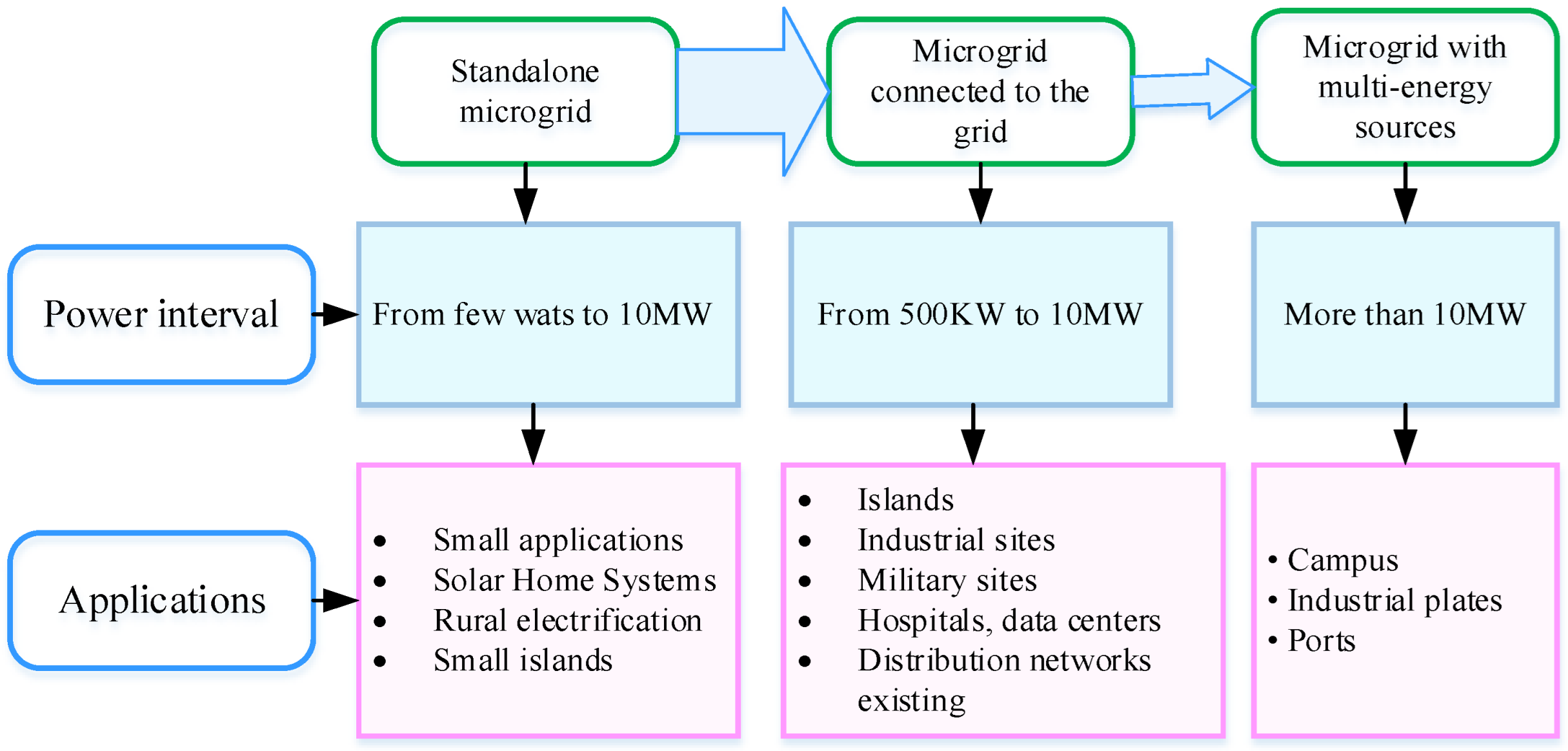
2.1. Representation of Different Categories of MGs

There are several types of MG. Figure 1 represents three categories of MGs: standalone, connected to the grid, and multi-energy sources. These MGs are distributed according to the power needed. The applications of MGs are used depending on their power interval.
A standalone MG is closed and is not connected to the grid. It is small and characterized by a power interval of a few Watts to some mega Watts. They are used for small applications. These MGs are generally used in areas where it is difficult to access the public network and are composed of renewable sources (PV, wind, etc.), a generator, and an ESS.
  • MGs connected to the grid use it as a principal source. Renewable energy sources can be used as secondary sources. These MGs are installed for applications with a medium power requirement for an interval between 500 KW and 10 MW.
  • MGs with multi-energy sources are used in larger installations that require higher energy. The energy implemented is more than 10 MW.
These MGs possess different produced power, control systems, operation modes, and control strategies. Figure 2 represents the characteristics of the MGs.

2.2. Representation of Different Bus Topologies

The energy distribution of a network can be constituted by high-power sources such as fissile energy, including nuclear energy, and coal power. MGs that use high power, based on sources such as PV, wind, etc., are changing the traditional structure scenario of power production. In an MG, the energy sources are generally situated near the loads; for this, the loads and generators can be decoupled from the grid, functioning in islanded mode. The selection of the energy source technologies for an MG is a complex issue; it is based on different characteristics, such as cost, lifespan, grants, energy efficiency, and the operation and maintenance cost.
In MGs that use renewable energy sources, the output power cannot be accurately controlled because of fluctuations in weather conditions and because the sources may not be enough to supply energy, necessitating the use of an ESS. It ameliorates the reliability of the global installation, supporting the power sources when they cannot provide the power required by the loads.
This system structure permits MGs to reduce the power losses in the electric distribution grid, ameliorates power capacity, and provides local voltage and frequency regulation support.
MGs have several electrical architectures, considering different bus voltage types. As such, MGs can be categorized as DC bus, AC bus, or hybrid AC/DC bus.

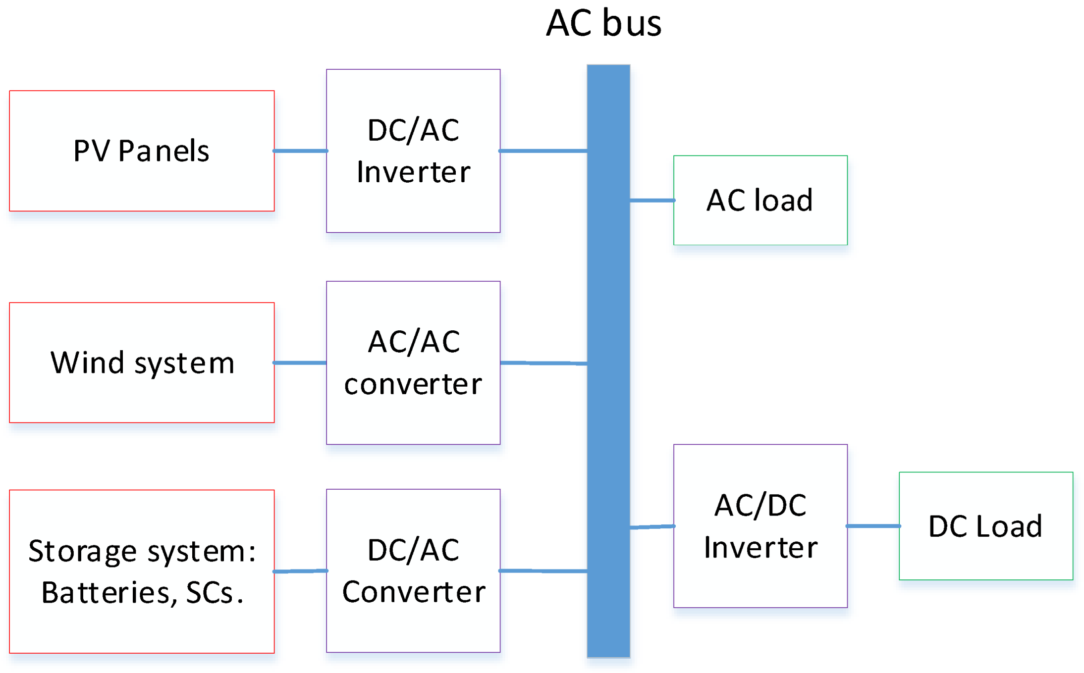
2.2.1. AC MG Architecture

The AC MG topology is presented in Figure 3. An AC MG is based on AC buses and any element used in this MG must be coupled by an AC interface; for this, all DC sources need a DC/AC inverter. The MG is coupled to the grid by one common point. This MG is composed of three parts: sources, energy storage devices, and AC loads. In AC topology, all sources are connected to a common AC bus through a specific power electronics device. The PV system is connected through a three-phase system inverter which is used to convert the DC output power to three-phase AC power. The energy storage system delivers DC energy which is converted to AC power through the implementation of a DC-AC inverter. This system can be directly used for the AC load. The DC load can be implemented through the use of AC/DC conversion.

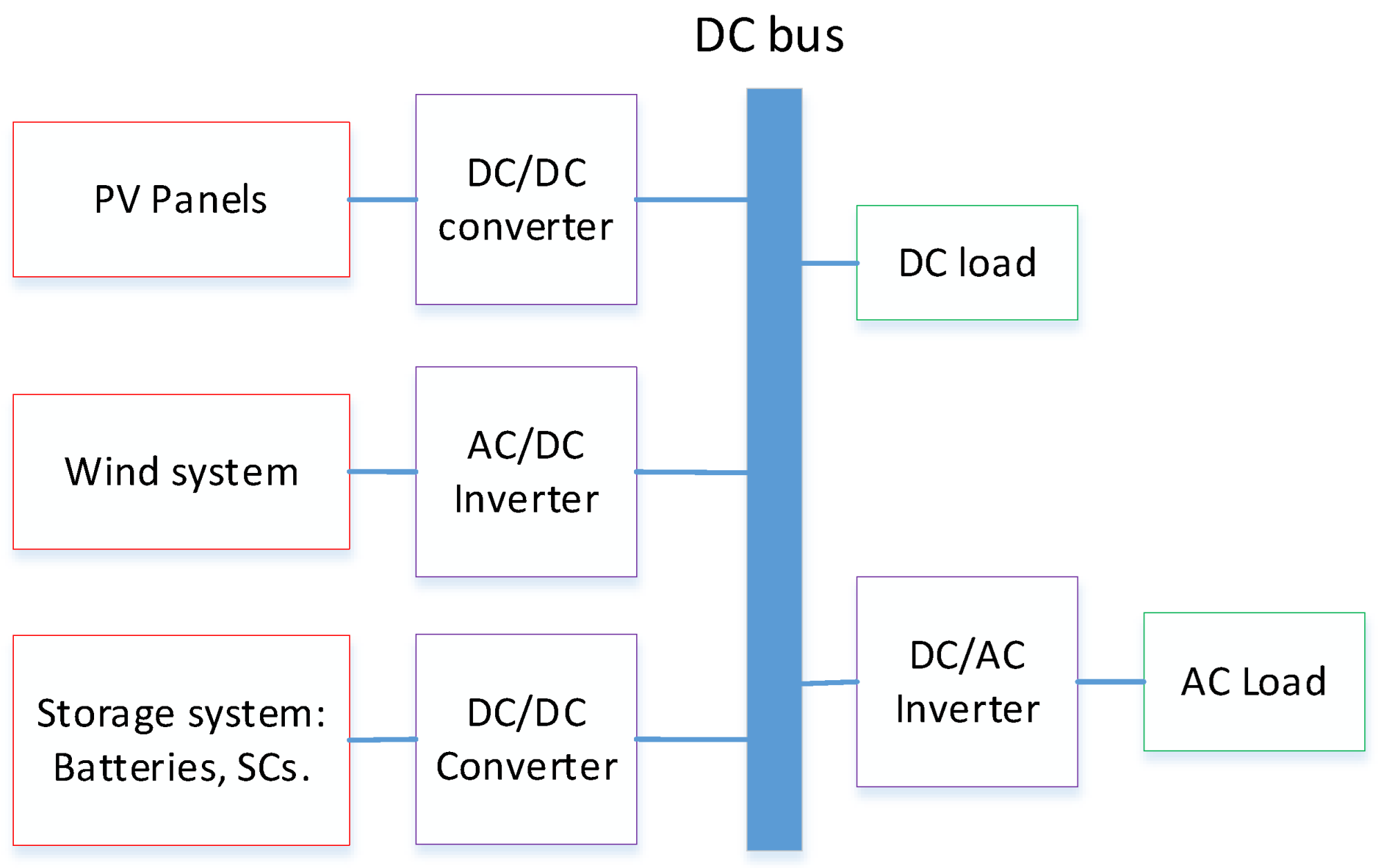
2.2.2. DC MG Architecture

The architecture of the DC topology for an MG is presented in Figure 4. In this topology, DC sources like PV panels are connected directly to the DC bus. AC sources like wind generators are connected to the DC bus through an AC/DC inverter. An energy storage system provides DC power which is connected to the DC bus through a buck–boost converter.

3. Global System Modeling

The AC-DC MG is shown in Figure 5. The common DC bus connects the following:
  • PV panels with a boost converter;
  • Batteries with a buck–boost bidirectional converter;
  • SCs with a buck–boot converter;
  • DC load directly;
  • AC load with a DC/AC inverter.
Figure 6 provides more details of the internal electrical models of the different devices.

3.1. Modeling of PV Panel

The PV model is implemented by one diode and a photocurrent. The leakage current is given by a shunt resistor Rp. The internal resistance is given by a series resistor Rs that expresses the current flow [31]. The PV current Ipv is given by the following equation [32].
I p v = I p h I s exp q V p v + I p v R s n s p v A k T c 1 I p v R s + V p v R p
The saturation current Is is presented by the following equation:
I s = I s , 0 T n T 3 exp q E g A k 1 T n 1 T
where Is,0 is the short-circuit current. The photocurrent Iph is given as (3), where ΔT = T − Tn.
I p h = I p h , n + K I Δ T G G n

3.2. Modeling of Supercapacitor

The chosen electrical model of the SC is given in Figure 6. This model is implemented with two parallel branches. The first branch is the fast branch of the SC, represented by R1C1, where it takes a few seconds. The second branch is the R2C2 cell, which shows a slow period that represents the behavior of the SC and takes a few minutes [33,34]. The voltage USC of the SC is given by:
U S C = N S s c v 1 + R 1 I S C N P s c ( C 1 = C 0 + C V v 1 )
Under consideration of the initial SC value C0, some values, including USC (SC pack voltage), ISC (SC pack current), vSC (elementary SC voltage), and iSC (elementary SC current), are defined. The equation of the voltage v2 is written as
V 2 = 1 C 2 i 2 d t = 1 C 2 1 R 2 ( v 1 v 2 ) d t .
where i 2 is the main capacitor C2 current.

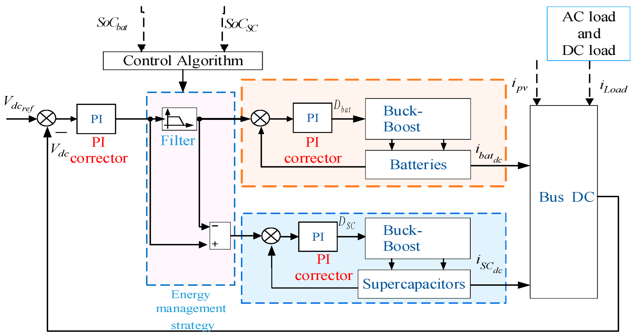
4. DC Bus Control Management of the MG

4.1. Presentation of the DC Bus Control

The system is controlled by the principle given in Figure 7. A PI controller is implemented to calculate I d c r e f to stabilize the DC bus voltage Vdc at 400 V. I b a t r e f and I S C r e f are given by a PMS for the converters connected to batteries and SCs in response to the needs of the load and the PV power variation. The I d c r e f , I S C r e f and I b a t r e f are given by the following equation:
I d c r e f = I S C r e f + I b a t r e f
A low-pass filter is implemented in order to eliminate the peak current on I b a t r e f I S C r e f is the difference between I d c r e f and I b a t r e f . However, SCs store the peak current in every change. The equations of the reference current of SCs I S C r e f * and the reference current of batteries I b a t r e f * are expressed as follows:
I b a t r e f * = I d c r e f 1 exp t T a u
I S C r e f * = I d c r e f exp t T a u
where Tau is the filter constant time.
The flowchart of the proposed EMS of the ESS that distributes energy between batteries and SCs is given in Figure 8. This flowchart explains the reference currents (charge and discharge) of batteries and SCs for the following:
  • Different SoCs (batteries and SCs) ( S o C S C 25 , S o C S C 95 , S o C b a t 25 , S o C b a t 95 ).
  • Different values of reference current of the DC bus:
    -
    I d c r e f 0 when PV panels provide more power than the demanded power by the load (excess of energy).
    -
    I d c r e f = 0 when PV panels produce the exact power demanded by the load.
    -
    I d c r e f < 0 when PV panels cannot provide the power demanded by the load (need of energy).

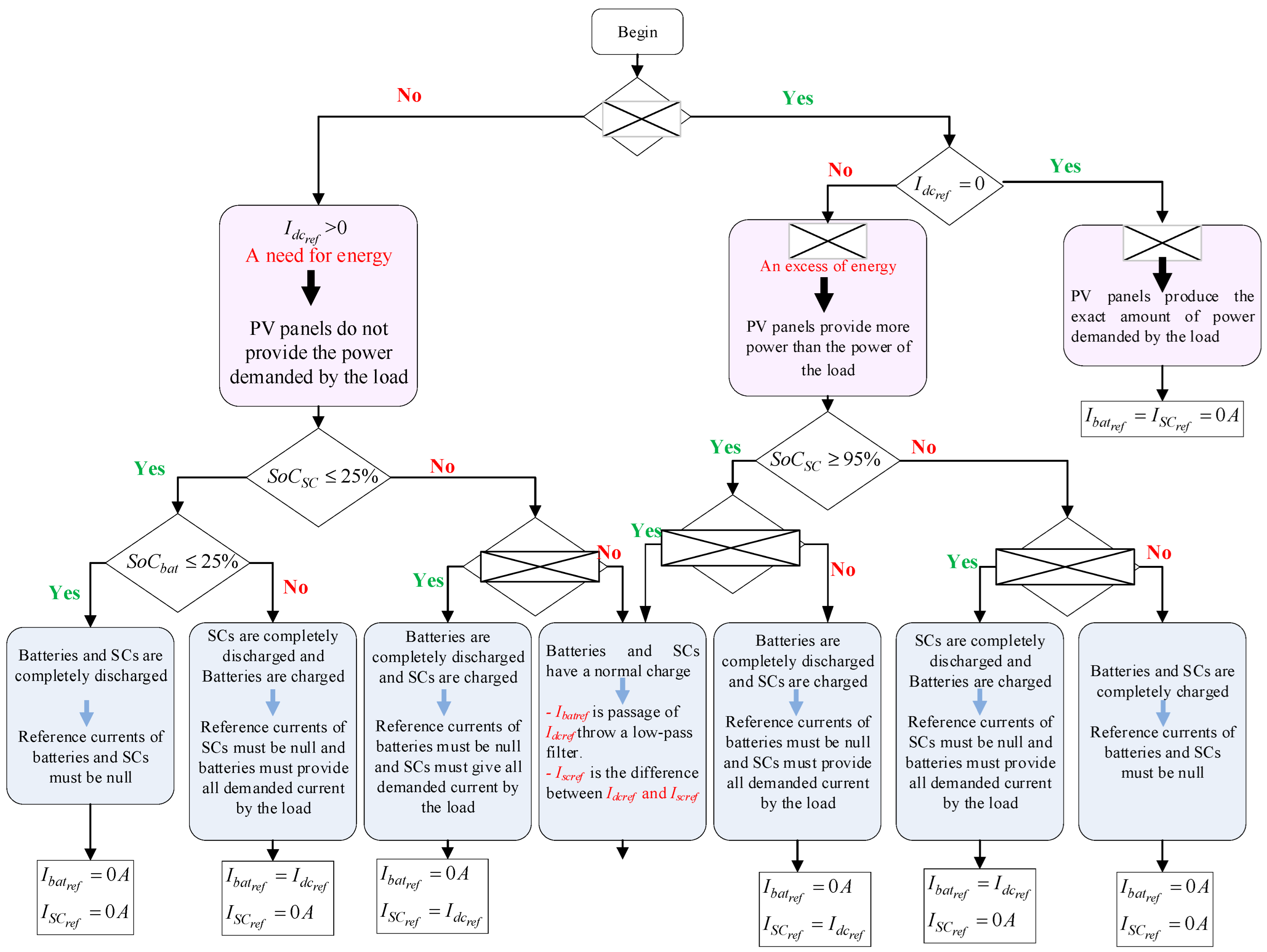
4.2. Logic Analysis of the Energy Management

The logic analysis is implemented for analyzing binary data by using Boolean functions (‘0’ or ‘1’). It is used in this paper in order to simplify the control of the EMS. It permits us to translate the flowchart to real applications. This analysis is based on logic functions: “Or” corresponds to an addition and “And” corresponds to a multiplication. For the analysis of the EMS, we proposed the addition of S1, S2, S3, S4, S5, S6, S7 and S ¯ 1 ,   S ¯ 2 ,   S ¯ 3 ,   S ¯ 4 ,   S ¯ 5 ,   S ¯ 6 ,   S ¯ 7 . For example, if S 1 = 1 (P positive), then S ¯ 1 = 0 (N negative). The flowchart given in Figure 9 summarizes the flowchart given in Figure 5. The Idcref current is divided into 3 parts ( S 1 I d c r e f < 0 , S 2 I d c r e f = 0 , S 3 I d c r e f > 0 ). As shown in this figure, the SoC of supercapacitors is divided into two parts ( S 4 S o C S C 25 , S 5 S o C S C 95 ) and the SoC of batteries is also divided into two parts ( S 6 S o C b a t 25 , S 7 S o C b a t 95 ).
  • I b a t r e f = 0 when the batteries and SCs are fully discharged; there is a need for energy when and batteries are fully discharged and the SCs are charged; there is no need for energy when the batteries are fully discharged and the SCs are charged; and there is no need for energy when the batteries and SCs are fully charged. The output F1 is equal to
F 1 = S 3 . S 4 . S 6 + S 1 . S 5 . S 7 + S 3 . S ¯ 4 . S 6 + S 1 . S ¯ 5 . S 7
F 1 = S 3 . S 6 S 4 + S ¯ 4 . + S 1 . S 7 S 5 + S ¯ 5
After simplification of Equation (10) by S 4 + S ¯ 4 = 1 and S 5 + S ¯ 5 = 1 , the equation will be written as follows:
F 1 = S 3 . S 6 + S 1 . S 7
  • I S C r e f = 0 when the batteries and SCs are fully discharged; there is a need for energy when the SCs are completely discharged and the batteries are charged; there is no need for energy when the SCs are completely discharged and the batteries are charged; and there is no need for energy when the batteries and SCs are fully charged. The output F2 is equal to
F 2 = S 3 . S 4 . S 6 + S 3 . S 4 . S ¯ 6 + S 1 . S 5 . S ¯ 7 + S 1 . S 5 . S 7
F 2 = S 3 . S 4 . S 6 + S ¯ 6 + S 1 . S 5 . S ¯ 7 + S 7
After simplification of Equation (13) by S 6 + S ¯ 6 = 1 and S 7 + S ¯ 7 = 1 , the equation will be written as follows:
F 2 = S 3 . S 4 + S 1 . S 5
  • I b a t r e f = I d c r e f when there is a need for energy, the SCs are fully discharged, and the batteries are charged; there is no need for energy when the SCs are fully discharged and the batteries are charged. It corresponds to F3 and is given by the following equation.
F 3 = S 3 . S 4 . S ¯ 6 + S 1 . S 5 . S 7
  • I S C r e f = I d c r e f when there is a need for energy, the batteries are fully discharged, and the SCs are charged; there is no need for energy when the batteries are fully discharged and the SCs are charged. It corresponds to F4 and is given by the following equation.
F 4 = S 3 . S ¯ 4 . S 6 + S 1 . S ¯ 5 . S 7
  • I b a t r e f = I b a t r e f * when the batteries and SCs have normal charge. It corresponds to F5 and is given by the following equation.
F 5 = S 3 . S ¯ 4 . S ¯ 6 + S 1 . S ¯ 5 . S ¯ 7
  • I S C r e f = I S C r e f * when the batteries and SCs have normal charge. It corresponds to F6 and is given by the following equation.
F 6 = S 3 . S ¯ 4 . S ¯ 6 + S 1 . S ¯ 5 . S ¯ 7
Figure 9 gives an example of how to find functions. This example is given for  I b a t r e f = I d c r e f .
The global schema including the inputs and outputs represented in Matlab/SIMULINK is given in Figure 10.
The inputs of the EMS are I d c r e f , S o C S C and S o C b a t . I d c r e f is compared with 0. S o C S C and S o C b a t are compared with 25% as a minimum state of charge and 95% as a maximum state of charge.
The outputs of the EMS are I S C r e f and I b a t r e f based on the Boolean equations.
Table 1 and Table 2 give the truth tables of the reference currents of batteries and SCs, respectively.

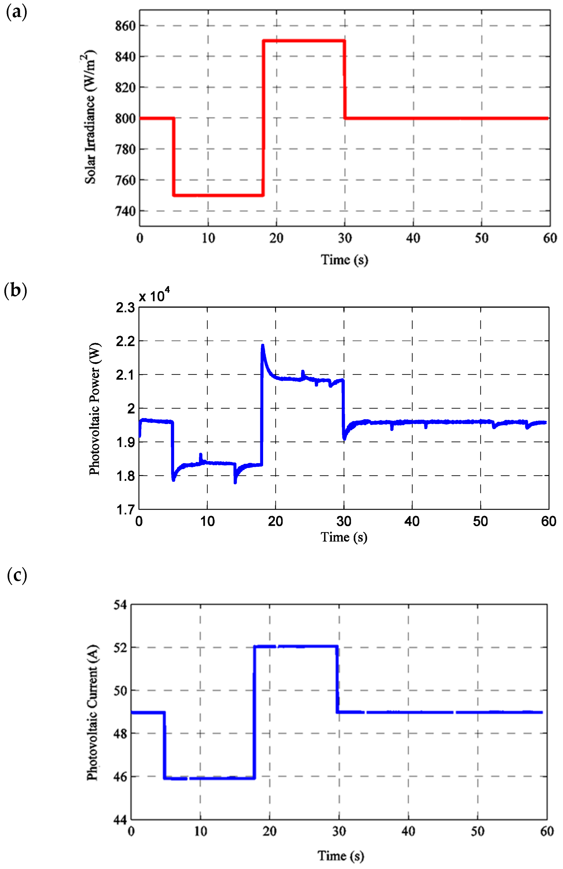
5. Simulation Results and Validation

The studied MG uses alternative and continuous loads. The energy storage is insured by an HESS. This system was simulated in MATLAB/Simulink to prove the efficiency of the EMS. These tests were executed with Tau  =  6 s of the low-pass filter and over a time period of 60 s. The DC bus voltage is 400 V. The batteries and SCs are considered initially charged. In this scenario, we propose the following:
  • For the PV source: a variation in solar irradiation;
  • For the AC load: a variation in the AC motor speed;
  • For the DC load: a variation in the DC load current.
Table 3 represents the different parameters used in this simulation test.
The solar irradiation was considered variable between t = 0 s and t = 30 s with Ir = [800; 750; 850] W/m2, and constant between t = 30 s and t = 60 s with Ir = 800 W/m2. This variation is shown in Figure 11a. The power of the PV generator is represented in Figure 11b. The PV current is given in Figure 11c, which followed the same change in solar irradiation. The first load was a DC load that was proposed as variable and is represented in Figure 12a. The second proposed load was an asynchronous motor that represents an AC load. The electromagnetic torque Te is given in Figure 12b, which represents fluctuations in every change in speed. Figure 12c depicts the reference and motor speeds. The stator current of the AC motor was represented between t = 15 s and t = 24 s and is given in Figure 12d. Battery and SC currents are presented in Figure 13a and Figure 13b, respectively. We observed that the SCs provided transient currents and eliminated the peak current, while batteries reacted more slowly to the requirements. Vdc is given in Figure 13c, and it was proposed to be constant at 400 V with slight fluctuations at every change in solar irradiation and motor speed.

6. Comparative Analysis

Different energy management methodologies and strategies for analyzing microgrids are presented in various articles. Among these methodologies, fuzzy logic control (FLC) is used for Grid-Connected Speed Control [35]. An advantage of FLC is the flexible framework that can be adapted to different types of devices and ecosystems, while a disadvantage is the methodology presents a complicated implementation and needs more attention.
Multi-Agent Optimization Strategies can also be implemented for microgrid energy management and generally give good results in EMSs. The disadvantage of this methodology is requirement of other software to ensure programming, like JAD [36].
AI-based techniques are also used in EMSs; a disadvantage is that they often require vast amounts of data to function effectively, which can lead to significant privacy concerns.
The proposed strategy presented in this paper is easy to implement and does not require additional software. This strategy can also be used in different applications like hybrid vehicles, power plants, and microgrids.

7. Conclusions

This paper presents an EMS for a DC MG with AC and DC loads. This MG uses a PV generator as a principal source with an HESS. Batteries and SCs are combined to make an ESS. The control of the DC bus voltage is presented by an EMS that delivers battery and SC reference currents. These currents control the buck–boost converters connected to the batteries and SCs. The strategy was simplified with a logic analysis that writes the inputs and output under a Boolean format. The simulation tests were executed at Tau  =  6 s of the low-pass filter and over a period of 60 s. The DC bus voltage was 400 V. It presented alternative and continuous loads that validate the control of the EMS and the logic analysis. It stabilizes the DC bus voltage, distributes energy between batteries and SCs, and eliminates the peak current on batteries. This proposed strategy is practical for different MGs based on a DC bus. This methodology can be used in different applications like electric vehicle management strategies by changing the agents. The implementation of AI-based techniques can also ameliorate the overall system. It can also be used in the amelioration of a battery management system.

Author Contributions

Writing—original draft, Z.C.; Writing—review & editing, D.C.; Project administration, S.H.L. All authors have read and agreed to the published version of the manuscript.

Funding

This work was funded by the research grant of Kongju National University in 2024 and by the Basic Science Research Program through the National Research Foundation of Korea (NRF) funded by the Ministry of Education (2022R1C1C1005975).

Data Availability Statement

The original contributions presented in this study are included in the article. Further inquiries can be directed to the corresponding author.

Conflicts of Interest

The authors declare no conflict of interest.

References

  1. Xu, Z.; Yang, P.; Zheng, C.; Zhang, Y.; Peng, J.; Zeng, Z. Analysis on the organization and Development of multi-microgrids. Renew. Sustain. Energy Rev. 2018, 81, 2204–2216. [Google Scholar] [CrossRef]
  2. Yin, C.; Wu, H.; Locment, F.; Sechilariu, M. Energy management of DC microgrid based on photovoltaic combined with diesel generator and supercapacitor. Energy Convers. Manag. 2017, 132, 14–27. [Google Scholar] [CrossRef]
  3. Das, K.; Nitsas, A.; Altin, M.; Hansen, A.D.; Sørensen, P.E. Improved load-shedding scheme considering distributed generation. IEEE Trans. Power Del. 2017, 32, 515–524. [Google Scholar] [CrossRef]
  4. Liao, H.; Milanović, J.V. Methodology for the analysis of voltage unbalance in networks with single-phase distributed generation. IET Gener. Transm. Distrib. 2017, 11, 550–559. [Google Scholar] [CrossRef]
  5. Zhou, X.; Zhou, L.; Chen, Y.; Guerrero, J.M.; Luo, A.; Wu, W.; Yang, L. A microgrid cluster structure and its autonomous coordination control strategy. Electr. Power Energy Syst. 2018, 100, 69–80. [Google Scholar] [CrossRef]
  6. Pereira, B.; Costa, G.R.M.; Contreras, J.; Mantovani, J.R.S. Optimal distributed generation and reactive power allocation in electrical distribution systems. IEEE Trans. Sustain. Energy 2016, 7, 975–984. [Google Scholar] [CrossRef]
  7. Merabet, A.; Ahmed, K.T.; Ibrahim, H.; Beguenane, R.; Ghias, A.M. Energy management and control system for laboratory scale microgrid based wind-pv-battery. IEEE Trans. Sustain. Energy 2017, 8, 145–154. [Google Scholar] [CrossRef]
  8. Lee, C.T.; Chu, C.C.; Cheng, P.T. A new droop control method for the autonomous operation of distributed energy resource interface converters. IEEE Trans. Power Electron. 2013, 28, 1980–1993. [Google Scholar] [CrossRef]
  9. Lidula, N.W.A.; Rajapakse, A.D. Microgrids research: A review of experimental microgrids and test systems. Renew. Sustain. Energy Rev. 2011, 15, 186–202. [Google Scholar] [CrossRef]
  10. Niknejad, P.; Venneti, S.; Vasefi, M.; Jeffryes, C.; Barzegaran, M.R. An electrochemically assisted AC/DC microgrid configuration with waste water treatment capability. Electr. Power Syst. Res. 2018, 162, 207–219. [Google Scholar] [CrossRef]
  11. Chen, W.; Zeng, Y.; Xu, C. Energy storage subsidy estimation for microgrid: A real option game-theoretic approach. Appl. Energy 2019, 239, 373–382. [Google Scholar] [CrossRef]
  12. Hu, J.; Shan, Y.; Xu, Y.; Guerrero, J.M. A coordinated control of hybrid ac/dc microgrids with PV-wind-battery under variable generation and load conditions. Electr. Power Energy Syst. 2019, 104, 583–592. [Google Scholar] [CrossRef]
  13. Baharizadeh, M.; Karshenas, H.R.; Guerrero, J.M. An improved power control strategy for hybrid ac-dc microgrids. Int. J. Electr. Power Energy Syst. 2018, 95, 364–373. [Google Scholar] [CrossRef]
  14. Khan, M.R.; Haider, Z.M.; Malik, F.H.; Almasoudi, F.M.; Alatawi, K.S.S.; Bhutta, M.S. A Comprehensive Review of Microgrid Energy Management Strategies Considering Electric Vehicles, Energy Storage Systems, and AI Techniques. Processes 2024, 12, 270. [Google Scholar] [CrossRef]
  15. Sugmar, B.K.; Anglani, N. A Novel Decision-Support Framework for Supporting Renewable Energy Technology Siting in the Early Design Stage of Microgrids: Considering Geographical Conditions and Focusing on Resilience and SDGs. Energies 2025, 18, 544. [Google Scholar] [CrossRef]
  16. Albasheri, M.A.; Bouchhida, O.; Soufi, Y.; Cherifi, A. Enhanced supervisor energy management technique of DC microgrid-based PV/wind/battery/SC. Electr. Eng. 2025, 107, 2285–2296. [Google Scholar] [CrossRef]
  17. Zemirline, N.; Kabeche, N.; Moulahoum, S. Artificial neural network controller for grid current quality improvement in solid-state transformers. J. Power Electron. 2024, 24, 799–809. [Google Scholar] [CrossRef]
  18. Mujammal, M.A.H.; Moualdia, A.; Wira, P.; Albasheri, M.A.; Cherif, A. Novel Direct Power Control Based on Grid Voltage Modulated Strategy Using Artifcial Intelligence. Smart Grids Sustain. Energy 2024, 9, 37. [Google Scholar] [CrossRef]
  19. Hartani, M.A.; Hamouda, M.; Abdelkhalek, O.; Mekhilef, S. Sustainable energy assessment of multi-type energy storage system in direct-current-microgrids adopting Mamdani with Sugeno fuzzy logic-based energy management strategy. J. Energy Storage 2022, 56, 106037. [Google Scholar] [CrossRef]
  20. Albasheri, M.A.; Bouchhida, O.; Soufi, Y.; Cherifi, A. Enhanced Vector Control of Induction Motor by Fuzzy Logic Controller. In Proceedings of the 2024 2nd International Conference on Electrical Enggineering and Automatic Control (ICEEAC), Setif, Algeria, 12–14 May 2024; pp. 1–5. [Google Scholar]
  21. Dhundhara, S.; Verma, Y.P.; Williams, A. Techno-economic analysis of the lithium-ion and lead-acid battery in microgrid systems. Energy Convers. Manag. 2018, 177, 122–142. [Google Scholar] [CrossRef]
  22. Mendis, N.; Muttaqi, K.M.; Perera, S. Management of low- and high-frequency power components in demand-generation fluctuations of a DFIG-based wind-dominated RAPS system using hybrid energy storage. IEEE Trans. Ind. Appl. 2014, 50, 2258–2268. [Google Scholar] [CrossRef]
  23. Dougal, R.A.; Liu, S.; White, R.E. Power and life extension of battery-ultracapacitor hybrids. IEEE Trans. Compon. Packag. Technol. 2002, 25, 120–131. [Google Scholar] [CrossRef]
  24. Li, W.; Joos, G. A power electronic interface for a battery supercapacitor hybrid energy storage system for wind applications. In Proceedings of the IEEE Power Electronics Specialists Conference, Rhodes, Greece, 15–19 June 2008; pp. 1762–1768. [Google Scholar]
  25. Cao, J.; Emadi, A. A new battery/ultracapacitor hybrid energy storage system for electric, hybrid, and plug-in hybrid electric vehicles. IEEE Trans. Power Electron. 2012, 27, 122–132. [Google Scholar]
  26. Krishna, C.M. Managing Battery and Supercapacitor Resources for RealTime Sporadic Workloads. IEEE Embed. Syst. Lett. 2011, 3, 32–36. [Google Scholar] [CrossRef]
  27. Cabrane, Z.; Ouassaid, M.; Maaroufi, M. Performance analysis of supercapacitor integration in photovoltaic energy storage system. In Proceedings of the 2015 3rd International Renewable and Sustainable Energy Conference (IRSEC), Marrakech, Morocco, 10–13 December 2015; pp. 1–6. [Google Scholar]
  28. Cabrane, Z.; Kim, J.; Yoo, K.; Lee, S.H. Comparative analysis of photovoltaic/rechargeable batteries sizing-dependent configurations for optimal energy management strategies in microgrids. J. Power Electron. 2022, 22, 841–849. [Google Scholar] [CrossRef]
  29. Feng, N.; Yan, L.; Liu, J.; Shi, M.; Zhou, J.; Chen, X. Fuzzy logic-based virtual capacitor adaptive control for multiple HESSs in a DC microgrid system. Electr. Power Energy Syst. 2019, 107, 78–88. [Google Scholar]
  30. Zhou, H.; Bhattacharya, T.; Duong, T.; Siew, T.S.T.; Khambadkone, A.M. Composite energy storage system involving battery and ultracapacitor with dynamic energy management in microgrid applications. IEEE Trans. Power Electron. 2011, 26, 923–930. [Google Scholar] [CrossRef]
  31. Rekioua, D.; Bensmail, S.; Bettar, N. Development of hybrid photovoltaic-fuel cell system for stand-alone application. Int. J. Hydrogen Energy 2014, 39, 1604–1611. [Google Scholar] [CrossRef]
  32. Poshtkouhi, S.; Palaniappan, V.; Fard, M.; Trescases, O. A general approach for quantifying the benefit of distributed power electronics for fine grained MPPT in photovoltaic applications using 3-D modeling. IEEE Trans. Power Electron. 2012, 27, 4656–4666. [Google Scholar] [CrossRef]
  33. Cabrane, Z.; Ouassaid, M.; Maaroufi, M. Management and control of the integration of supercapacitor in photovoltaic energy storage. In Proceedings of the IEEE International Conference on Green Energy Conversion Systems (GECS), Hammamet, Tunisia, 23–25 March 2017; pp. 1–6. [Google Scholar]
  34. Cabrane, Z.; Ouassaid, M.; Maaroufi, M. Performance enhancement of Solar Vehicle by integration of supercapacitors in the energy storage system. In Proceedings of the IEEE International Renewable and Sustainable Energy Conference (IRSEC), Marrakech, Morocco, 14–17 November 2016; pp. 62–67. [Google Scholar]
  35. Arévalo, P.; Ochoa-Correa, D.; Villa-Ávila, E.; Iñiguez-Morán, V.; Astudillo-Salinas, P. Systematic Review of Hierarchical and Multi-Agent Optimization Strategies for P2P Energy Management and Electric Machines in Microgrids. Appl. Sci. 2025, 15, 4817. [Google Scholar] [CrossRef]
  36. Wang, Y.; Cao, Y.; Qian, Z.; Xia, J.; Kang, X.; Zhu, Y.; Yang, Y.; Zhang, W.; Chen, S.; Wu, G. Research on Grid-Connected Speed Control of Hydraulic Wind Turbine Based on Enhanced Chaotic Particle Swarm Optimization Fuzzy PID. Algorithms 2025, 18, 187. [Google Scholar] [CrossRef]
Figure 1. Representation of different categories of MGs.
Batteries 11 00245 g001
Figure 2. Characteristics of MGs.
Batteries 11 00245 g002
Figure 3. AC-coupled MG architecture.
Batteries 11 00245 g003
Figure 4. DC-coupled MG architecture.
Batteries 11 00245 g004
Figure 5. Diagram of an AC/DC MG.
Batteries 11 00245 g005
Figure 6. Electric schematic of AC/DC MG.
Batteries 11 00245 g006
Figure 7. Schematic of the DC bus control diagram.
Batteries 11 00245 g007
Figure 8. EMS flowchart of the ESS between the batteries and SCs.
Batteries 11 00245 g008
Figure 9. Simplified EMS flowchart.
Batteries 11 00245 g009
Figure 10. Representation of the EMS MATLAB/SIMULINK 2019a.
Batteries 11 00245 g010
Figure 11. Photovoltaic panel parameters with a variation in solar irradiation in this approach: (a) solar irradiation, (b) PV power, (c) PV current.
Batteries 11 00245 g011
Figure 12. AC load parameters with a variation in AC motor speed in this approach: (a) DC load current, (b) electromagnetic torque of the motor, (c) motor speed, (d) stator current.
Batteries 11 00245 g012
Figure 13. DC load parameters with a variation in the DC current of the load in this approach: (a) battery current, (b) SC current, (c) DC bus voltage.
Batteries 11 00245 g013
Table 1. Truth table of the reference current of batteries.
F1F2Output I b a t r e f
0000
011 I b a t r e f *
101 I d c r e f
111Impossible
Table 2. Truth table of the reference current of SCs.
F4F5Output I S C r e f
0000
011 I S C r e f *
111 I d c r e f
111Impossible
Table 3. Overall system characteristics.
Switching Frequencyf = 5000 kHz
Maximum load powerPch-max = 48 kW
DC busVdc = 400 VCdc = 5.4 mF
PI corrector K i d c = 0.36 K p d c = 0.0025
Photovoltaic panelsVpv = 200 V
Associated converterLpv = 10 mH
SupercapacitorsVsc = 300 V
Associated converterLsc = 15 mH
PI corrector K i s c = 8.3 K p s c = 0.037
BatteriesVbat = 300 V
Associated converterLbat = 15 mH
PI corrector K i b a t = 8.3 K p b a t = 0.037
Disclaimer/Publisher’s Note: The statements, opinions and data contained in all publications are solely those of the individual author(s) and contributor(s) and not of MDPI and/or the editor(s). MDPI and/or the editor(s) disclaim responsibility for any injury to people or property resulting from any ideas, methods, instructions or products referred to in the content.

