Article

Synergistic Cationic–Anionic Regulation in Ni-Doped FeSe@C Anodes with Se Vacancies for High-Efficiency Sodium Storage

1
School of Materials Science and Engineering, Anhui University of Technology, Maanshan 243002, China
2
Anhui Province Key Laboratory of Efficient Conversion and Solid-State Storage of Hydrogen & Electricity, Anhui University of Technology, Maanshan 243002, China
*
Author to whom correspondence should be addressed.
Batteries 2025, 11(6), 205; https://doi.org/10.3390/batteries11060205
Submission received: 24 April 2025 / Revised: 21 May 2025 / Accepted: 22 May 2025 / Published: 23 May 2025

Abstract

:
Sodium-ion batteries present an economical energy storage solution, yet their anode kinetics remain slow, impeding rate performance and cyclability. Layered FeSe anodes, characterized by metallic conductivity, hold potential, but structural decay and insufficient active sites during cycling continue to pose challenges. Herein, these challenges are addressed through the implementation of dual Ni doping and Se vacancy engineering in FeSe@C to synergistically regulate cationic/anionic configurations. The ionic substitution of larger Fe2+ ions (0.78 Å ionic radius) with smaller Ni2+ ions (0.69 Å) induces lattice distortion and generates abundant Se vacancies, enhancing electron transport, active site accessibility, and Na+ adsorption. These synergistic modifications effectively boost Na+ diffusion kinetics and electrolyte compatibility, creating a favorable electrochemical environment for fast sodium storage. Consequently, the optimized 2%Ni-FeSe@C electrode retains an exceptional discharge specific capacity of 307.67mAh g−1 after 1000 cycles at an ultrahigh current density of 5 Ag−1, showcasing superior rate capability and long-term cycling stability, paving the way for practical high-power SIBs.

1. Introduction

Lithium-ion batteries (LIBs) stand as a preeminent electrochemical energy storage technology, renowned for their exceptional energy density and robust cycle stability, which underpin their critical roles within the fields of portable electronics, electric vehicles, as well as grid-level energy storage systems [1]. Nevertheless, the escalating costs and scarcity of global lithium resources have driven a critical research shift toward SIBs, which utilize sodium—a naturally abundant and cost-effective alkali metal—as the charge carrier [2,3,4]. Although SIBs exhibit substantial potential for giga-scale energy storage deployment, their practical realization is constrained by the limitations of commercial anode materials: conventional graphite anodes, which are unsuitable for Na+ intercalation owing to the more extended ionic radius of Na+ (1.02 Å versus Li+ 0.76 Å), suffer from inadequate specific capacity and limited cycle durability [5,6]. While hard carbon, a prevalent alternative anode material for SIBs, alleviates certain intercalation challenges, its amorphous structure inherently leads to inferior electrical conductivity and substantial irreversible capacity loss, thus necessitating the investigation of high-performing anode materials with optimized architectures [7].
Transition metal dichalcogenides (TMDs), exemplified by iron selenide (FeSe), have emerged as prospective anode materials on account of their high theoretical specific capacity, abundant iron resource availability, and excellent electrical conductivity [8]. Nonetheless, FeSe-based anodes are plagued by intrinsic limitations, encompassing inefficient active material utilization, sluggish ion transport kinetics, and irreversible structural degradation during sodiation/desodiation, which collectively constrain their specific capacity and rate capability [9,10]. To tackle these challenges, researchers have investigated vacancy engineering and anion doping strategies to regulate electronic structures and boost electrochemical reactivity [11,12,13]. For instance, anion doping can create active sites and enhance alkali ion adsorption, and the abundant vacancies can induce lattice distortion and thus enhance reaction transport kinetics.
However, this strategy is primarily focused on cation or anion (e.g., S/Se) modifications, with scant research dedicated to dual doping and vacancy engineering [14]. Notably, the synergistic combination of cation doping and vacancy engineering—especially when involving metal cations with adjustable concentrations—remains largely unexplored in FeSe-based materials. Although cation doping is theoretically capable of inducing lattice distortion and electron redistribution to enhance ion storage kinetics, no universal synthesis method has been reported to achieve precise control over both cation doping ratios and vacancy formation simultaneously [3,15].
In this work, the research gap is bridged by constructing Ni-doped FeSe@C (2%Ni-FeSe@C) via a hydrothermal doping and selenization protocol. Given that the ionic size of Ni2+ (0.69 Å) is of a smaller magnitude than that of Fe2+ (0.78 Å), the Se vacancy concentration is deliberately enhanced and charge density redistribution is induced in FeSe-based anode material, thereby improving its electron mobility and enriching surface active sites [16,17]. The Ni-doped carbon layer additionally boosts electrical conductance and mitigates structural stress throughout repeated charge–discharge processes. Electrochemical characterizations reveal that the optimized 2%Ni-FeSe@C anode demonstrates a high degree of reversibility specific capacity of 427.65 mAh g−1 at a current density of 1 A g−1 after 100 cycles, and retains 307.67mAh g−1 after 1000 cycles at 5 Ag−1, demonstrating its exceptional rate capability and long-term cyclability.

2. Experimental Section

2.1. Synthesis of 2%Ni-FeOOH@C Nanomaterial

Initially, FeCl3·6H2O (0.2705 g), CO(NH2)2 (0.63 g), and Ni(NO3)2·6H2O (0.00884 g) were disintegrated in 50 mL of ethylene glycol and underwent magnetic stirring for 30 min. The solution was afterward moved to a 100 mL stainless steel reactor and heated at a rate of 5 °C min−1 from room temperature to 170 °C over a period of 10 h. Following this, the reactor was naturally reduced to room temperature. The resulting light green precipitate was washed once with distilled water and twice with anhydrous ethanol. The final product, 2%Ni-FeOOH@C, appeared as a green powder and was dried overnight in a vacuum oven at 60 °C.

2.2. Synthesis of 2%Ni-FeSe@C Nanomaterial

Thereafter, 100 milligrams of the manufactured 2%Ni-FeOOH was disintegrated in 100 mL of a buffer solution consisting of Tris (prepared by mixing 40 mL of water with ions eliminated and 60 mL of anhydrous ethanol with 121 mg of tris (hydroxymethyl) aminomethane) and sonicated for 30 min. Thereafter, 60 mg of dopamine hydrochloride was introduced, and the mixture was magnetically stirred for 24 h. Finally, 100 mg of 2%Ni-FeOOH@C powder was selenized with selenium powder at a mass ratio of 1:4 within a tubular furnace under a mixed atmosphere of argon (90%) and hydrogen (10%), heated at 560 °C for 9 h characterized by a heating rate of 2 °C min−1, to attain the final product 2%Ni-FeSe@C. The overall synthesis yield was about 75.8%. The control samples were synthesized via the same routes except for adding different amounts of Ni(NO3)2·6H2O. For more detailed information, materials, material characterization, and electrochemical measurements are provided in the Supporting Information.

3. Results and Discussion

Figure 1a is the flow chart for the preparation of 2%Ni-FeSe@C. Initially, 2%Ni-FeOOH@C was meticulously fabricated via the hydrothermal synthesis approach. Subsequently, 2%Ni-FeSe@C was successfully synthesized through the process of high-temperature selenization, which represents a crucial post-treatment step for material transformation and property enhancement.
Figure 1b presents the XRD patterns associated with the as-prepared samples. The diffraction peaks at 30.4°, 32.4°, 42.2°, 50.5°, and 55.3° are indexed to the (002), (101), (102), (110), and (103) crystal planes of hexagonal FeSe (H-FeSe, PDF#75-0608), respectively, confirming the successful synthesis of the hexagonal phase. Additionally, the weak diffraction peaks detected at 2θ = 28.7° and 47.4° are linked to the tetragonal phase of FeSe (T-FeSe, PDF#85-0735), indicating the coexistence of minor tetragonal structural domains. The layered architecture of the minor tetragonal phase, characterized by an expanded interlayer spacing of 0.59 nm, facilitates rapid sodium-ion intercalation/deintercalation, thereby enhancing cycle stability [18]. High-resolution analysis of the 30–45° diffraction region as shown in Figure 1c reveals that increasing Ni-doping ratios cause high-intensity (101) and (102) peaks to shift to higher angles. This peak shift is primarily attributed to lattice distortion induced by the substitution of Fe2+ with Ni2+, owing to the narrower ionic radius of Ni2+ (0.69 Å) compared to Fe2+ (0.78 Å). The ionic radius mismatch generates lattice strain during cation substitution, driving the observed diffraction peak displacement [19]. Raman spectroscopy (Figure 1d) reveals that both samples exhibit characteristic D-band (1346 cm−1, amorphous carbon) and G-band (1585 cm−1, graphitic carbon) signals, confirming the presence of carbon in the composites. The IG/ID intensity ratio of 2%Ni-FeSe@C increases to 1.14, compared with 0.86 for FeSe@C, reflecting a higher degree of structural disorder in the carbon layer. Such an increase ratio suggests reduced graphitization quality, which introduces more defects to facilitate electron transport and ion diffusion [20].
To characterize the microstructure and morphology of FeSe@C and 2%Ni-FeSe@C samples, SEM analysis was performed as exhibited in Figure 2a–d. The SEM images reveal that both samples exhibit spherical particles with diameters of approximately 3 μm, and distinct lamellar stacking structures are observed on their surfaces. Compared with FeSe@C, 2%Ni-FeSe@C particles exhibit a more uniform size distribution and regular morphology. The distinct structural features not only facilitate Na+ transport and enhance electrolyte penetration but also further reduce interfacial charge transfer resistance [21,22], thereby improving the material’s overall electrochemical performance [23,24]. HRTEM analysis (Figure 2e–h) indicates that the (102) crystal plane of 2%Ni-FeSe@C demonstrates an interplanar spacing of 0.214 nm, and the entire structure is consistently sheathed by a layer containing carbon. This uniform coating composed of carbon effectively mitigates volume expansion that occurs during charge–discharge cycles, providing structural durability for long-term electrochemical performance [21]. Elemental mapping analysis (Figure 2i,j) manifests that Fe, Ni, Se, N, and C are homogeneously distributed throughout the particles of 2%Ni-FeSe@C. This observation indicates addition of N to the carbon layer through the doping process, which alters the carbon structure and facilitates electrical conductivity. The homogeneous distribution of Ni further evidences the uniform substitution of Fe sites in FeSe by Ni2+, consistent with the XRD peak shift discussed earlier. Brunauer–Emmett–Teller (BET) measurements (Figure S1) demonstrate that 2%Ni-FeSe@C exhibits a high specific surface coverage of 118.3 m2 g−1, significantly larger than the 85.8 m2 g−1 observed for FeSe@C. This enhanced BET surface area increases the count of active sites situated on 2%Ni-FeSe@C, thereby boosting its electrochemical activity. The EPR characterization (Figure S4) confirms the presence of selenium vacancies in both 2%Ni-FeSe@C and FeSe@C, as evidenced by the distinct resonance signals at g = 2.003, which aligns with the well-documented signature of Se vacancies in metal selenides.
XPS was utilized to characterize the composition and chemical nature of the surface bonding states of pristine FeSe@C and 2%Ni-FeSe@C samples. The XPS profiles of FeSe@C (Figure 3a) clearly exhibit characteristic peaks for Fe, Se, N, C, and Ni. This demonstrates the successful insertion of N and Ni into the lattice during the doping process. In the Se 3d high-resolution XPS spectrum (Figure 3b), the peaks at 53.9 eV and 55.8 eV are assigned to Se 3d5/2 and Se 3d3/2 spin-orbit split states, respectively. A weak peak at 59 eV is ascribed to the Se-O bond, originating from the surface oxidation of selenium species [25]. The shift in Se 3d peak positions is attributed to Ni doping and Se vacancies indirectly modulating the electron cloud distribution around Se atoms [26]. The Fe 2p high-resolution XPS spectrum (Figure 3c) is deconvoluted into six subpeaks, with characteristic peaks at 710.8 eV and 724.2 eV assigned to Fe 2p3/2 and Fe 2p1/2 spin-orbit split states, respectively, exhibiting an energy separation (ΔEFe) of 13.4 eV. These peaks confirm the presence of Fe2+ in both FeSe@C and 2%Ni-FeSe@C samples. Additional peaks at 713.6 eV and 725.3 eV are attributed to Fe3+, indicating the formation of a higher iron oxidation state [27]. Notably, Ni doping induces a significant negative shift in the binding energies of both Fe2+ and Fe3+ peaks. Additionally, a peak at 706 eV, assigned to metallic Fe (Fe0), arises from the partial reduction during the annealing process [28]. In the C 1s high-resolution XPS spectrum (Figure 3d), three characteristic peaks at 285.0 eV, 286.7 eV, and 288.0 eV are assigned to C–C, C=O, and O–C=O groups, respectively. In the N 1s high-resolution XPS spectrum (Figure 3e), three minor peaks at 398.5 eV, 400.7 eV, and 403.9 eV are consistent with pyridinic-N, pyrrolic-N, and graphitic-N, respectively [29]. Pyrrolic-N effectively boosts electrochemical reaction activity and electrical conductivity, with such enhancement primarily attributed to N-doping-induced structural defects on the carbon surface, and Ni2+ substitution induces Se vacancies (Figure 3b and Figure S4), while pyrrolic-N optimizes the carbon layer’s electronic environment, collectively promoting surface-dominated pseudocapacitive Na+ storage (90.3% contribution at 1 mV s−1) [30]. The high-resolution XPS spectrum of Ni 2p for 2%Ni-FeSe@C (Figure 3f) shows clearly discernible spin-orbit split peaks of Ni 2p1/2 and Ni 2p3/2 at 873.0 eV and 875.0 eV, respectively, indicating the successful incorporation of Ni into the FeSe lattice.
To elucidate the reaction mechanism of 2%Ni-FeSe@C, the cyclic voltammetry (CV) measurement was conducted as shown in Figure 4a. The first anodic scan exhibits four distinct reduction peaks at ~1.06 V, ~0.78 V, ~0.20 V, and 0.08V, respectively. The sharp peak at ~1.06 V is attributed to the formation of NaxFeSe and a solid electrolyte interphase (SEI) via electrolyte decomposition [31]. A second cathodic peak at 0.78 V was assigned to the conversion reaction of NaxFeSe to Fe and Na2Se (NaxFeSe + (2 − x) Na+ + (2 − x) e → Fe + Na2Se) [32,33,34]. The subsequent charge/discharge CV curves tend to be stable, indicating the 2%Ni-FeSe@C exhibits good stability toward sodiation/desodiation [18]. In addition, there is a pair redox peaks closing to 0 V, which should be attributed to sodium-ion intercalation/deintercalation into carbon layers [21]. During the cathodic scan, oxidation peaks at ~1.52 V, ~1.80 V, and ~2.05 V are assigned to the conversion reactions of Se species in NaxFeSe and FeSe [32,33,34,35]. Starting from the second cycle, the anodic scan exhibits a pronounced reduction peak near 0.78 V, with subsequent CV curves stabilizing, signifying the excellent stability of 2%Ni-FeSe@C during sodium insertion/extraction cycles. In pristine FeSe@C (Figure S3), the reduction peak at 1.3 V corresponds to irreversible phase decomposition (FeSe + 2Na+ + 2e → Fe + Na2Se), which is fully suppressed in 2%Ni-FeSe@C due to Ni²+-induced lattice stabilization and strengthened Fe–Se bonding. Concurrently, the emergence of a 1.80 V oxidation peak exclusively in the doped material aligns with the Ni2+/Ni3+ redox couple activation. This Ni-mediated process not only replaces the detrimental decomposition pathway but also facilitates reversible Na+ storage through enhanced interfacial charge transfer [35].
The overlapping CV curves indicate the excellent reversibility, as corroborated by the galvanostatic charge–discharge (GCD) curves (Figure 4b). The active electrode was fabricated with a geometric area of 1.13 cm2 and a total mass loading of about 1 mg cm−2. At a current density of 0.1 A g−1, the electrode exhibits initial discharge and charge capacities of 565.4 and 510.7 mAh g−1, respectively, yielding an initial Coulombic efficiency (ICE) of 90.32%. The relatively low ICE is attributed to instability of the solid electrolyte interphase (SEI) and irreversible phase transformations [33,36,37]. The initial discharge and charge capacities of FeSe@C are measured at 551.7 and 475.1 mAh·g−1, respectively, with an initial Coulombic efficiency (ICE) of 86.12% (Figure S2), markedly inferior to those of 2%Ni-FeSe@C. This disparity underscores the efficacy of Ni doping in boosting initial Coulombic efficiency. Furthermore, rate capability assessments conducted over current densities spanning 0.1 to 5 A g−1 (Figure 4c) reveal the exceptional capacity retention of 2%Ni-FeSe@C. It sustains capacities of 521.2, 515.7, 503.9, 474.6, 413.1, and 355.8 mAh g−1 at 0.1, 0.2, 0.5, 1, 2 and 5 Ag−1, respectively, significantly outperforming other samples.
In terms of cycling stability (Figure 4d), 2%Ni-FeSe@C retains a discharge capacity of 427.65 mAh g−1 after 100 cycles at 1 Ag−1, surpassing FeSe@C (340.3 mAh g−1), 1%Ni-FeSe@C (376.3 mAh g−1), and 3%Ni-FeSe@C (366.6 mAh·g−1), respectively. Even at an extremely high current density of 5 A g−1 as exhibited in Figure 4e, 2%Ni-FeSe@C maintains an overall reversible capacity of 307.67 mAh g−1 after 1000 cycles, whereas FeSe@C delivers only 244.1 mAh g−1. This superior cycle performance is attributed to Ni doping enhancing the structural stability of FeSe. A comparison of reported SIB anodes (Figure 4f) confirms that 2%Ni-FeSe@C exhibits excellent cycling stability, which is attributed to its unique nanosheet structure, cation doping, and Se vacancies enabling fast ion/electron transport [8,32,34,38,39,40].
Figure 4. (a) CV curves of 2%Ni-FeSe@C at 0.1 mV s−1; (b) charge–discharge curves of 2%Ni-FeSe@C for the first three cycles; (c) rate behavior and (d) cycling behavior of the four electrodes; (e) cycling behavior at 5 Ag−1 for the FeSe@C and 2%Ni-FeSe@C electrodes; (f) contrast of the electrochemical behavior with the reported selenides anode materials [8,19,21,32,34,37,38,39].
Batteries 11 00205 g004
CV curves with varying scan rates were applied to evaluate the electrochemical kinetics and reversibility of FeSe@C and 2%Ni-FeSe@C, as shown in Figure 5a,b. Peak 1 and peak 2 are assigned to the conversion reactions of Se species in NaxFeSe and FeSe [32,33,34]. Meanwhile, peak 3 is assigned to the conversion of NaxFeSe into Fe and Na2Se [18]. The images reveal that the curves maintain their shape with the increasing scan rates and exhibit negligible peak shifts, suggesting that the 2%Ni-FeSe@C electrode undergoes mild polarization and demonstrates excellent electrochemical reversibility [41,42,43].
The diffusion coefficient of Na+ can be estimated using Equation (1):
I P = 2.69   ×   10 5 n 2 / 3 AC v 1 / 2 D Na + 1 / 2
where Ip is the peak current (A) at different scan rates, n is the charge transfer number, A is the electrode surface area, C is the molar concentration of Na+ (mol cm−3), and v is the scan rate. Based on the fitting results of Figure 5c,d, the diffusion coefficients of 2%Ni-FeSe@C during the redox processes of Peaks 1, 2, and 3 are calculated to be 1.34 × 10⁻⁹, 1.86 × 10⁻⁹, and 2.19 × 10⁻⁹ cm2 s−1, respectively. In contrast, the Na+ diffusion coefficients of FeSe@C are only 1.26 × 10⁻⁹, 1.75 × 10⁻⁹, and 2.16 × 10⁻⁹ cm2 s−1, respectively.
Based on the relationship between the peak current (i) and the scan rate (v), the contributions of diffusion control and surface pseudocapacitive control to the Na+ storage performance of FeSe@C and 2%Ni-FeSe@C can be quantitatively analyzed as Equations (2)–(4):
i = a v b
log i = b log v + log a
I = k 1 v + k 2 v 1 / 2
where k1v represents the current contribution from pseudocapacitive effects, and k2v1/2 corresponds to the current contribution from diffusion-controlled processes, with k1 and k2 being adjustable parameters. By fitting the values of k1 and k2, the total current response (I) at a specific voltage can be decomposed into two components: pseudocapacitive effects (k1v) and diffusion effects (k2v1/2), thereby quantifying the proportion of pseudocapacitive contribution during Na+ storage.
Figure 6a–d show that the pseudocapacitive contributions of 2%Ni-FeSe@C are 71.6%, 73.2%, 76.9%, 81.3%, 85.1%, and 90.3% at scan rates of 0.1, 0.2, 0.4, 0.6, 0.8, and 1 mV s−1, respectively, significantly higher than that of FeSe@C (66.9%, 72.3%, 76.3%, 80.2%, 84.4%, and 87.8%). This indicates that 2%Ni-FeSe@C exhibits superior fast charge–discharge kinetics. Quantitative analysis of the relative contributions from pseudocapacitive and diffusion-controlled mechanisms further confirms that 2%Ni-FeSe@C more effectively utilizes surface pseudocapacitive processes during fast charge–discharge, thereby significantly enhancing its rate performance.
Systematic studies of interfacial reaction resistance were conducted using EIS. As shown in Figure 7a, the Nyquist plots of both samples exhibit typical characteristics: semicircular arcs appear in the intermediate-frequency region, pertaining to charge transfer resistance (Rct) [21]; and sloped lines appear in the low-frequency region, corresponding to Warburg impedance (Ws). Among them, the charge transfer resistance (Rct) reflects the charge transfer process at the electrolyte/electrode interface, while the Warburg impedance (Ws) represents the diffusion behavior of Na+ within the electrode material—the slope of which is closely related to the diffusion coefficient of Na+ in the material.
The diffusion coefficient of Na+ (DNa+) and the exchange current density (I0) can be calculated using Equations (5) and (6) below [44].
D Na + = R 2 T 2 / 2 A n 4 F 4 c 2 σ 2
I 0   = RT / nF R ct
Among them, R, T, A, n, F, c, and σ denote the gas constant (8.314 J K−1 mol−1), temperature, the area of the disk electrode, the number of electrons, the Faraday constant, the molar concentration of Na+, and the Warburg coefficient, respectively. According to these formulas, the value of σ can be determined by the slope of the linear relationship between Z′ and ω−1/2 in the low-frequency region (Figure 7b). The corresponding electrochemical impedance spectroscopy (EIS) data fitted using the equivalent circuit are summarized in Table 1. The results show that 2%Ni-FeSe@C exhibits the lowest charge transfer resistance (101 Ω), the lowest σ value (106.5 Ω S−1/2), and the largest Na+ diffusion coefficient (DNa+, 3.13 × 10⁻⁸ cm2 S−1). These results indicate that 2%Ni-FeSe@C demonstrates a superior performance in terms of charge transfer and Na+ diffusion kinetics. This can be attributed to the fact that nickel doping leads to the rearrangement of charge density and additional lattice distortion in FeSe.
To clarify the kinetic differences between 2%Ni-FeSe@C and FeSe@C—particularly regarding their distinct rate capabilities—the galvanostatic intermittent titration technique (GITT) was employed. A 0.1 A g−1 pulse current was applied for 30 min, followed by 60 min rest intervals, to determine the apparent Na+ diffusion coefficient within the electrodes of both materials.
Figure 8a shows the characteristic potential plateaus corresponding to Na+ desodiation and sodiation processes. Figure 8b indicates that the potential change (ΔV) in FeSe@C during the relaxation phase is 0.26 V, significantly higher than that of 2%Ni-FeSe@C (0.20 V). This can be attributed to the introduction of Se vacancies by Ni doping, which serve as fast diffusion pathways for Na+ and shorten the ionic migration distance. Additionally, Ni may inhibit the agglomeration, thereby reducing the contribution of diffusion impedance to ΔV.
Based on Fick’s second law of diffusion, the DNa+ can be estimated using Equation (7) [45,46,47].
D Na + = 4 Π τ m B V M M B A 2 Δ E s Δ E τ 2
where MB is the molar mass, VM denotes the molar volume, mB represents the sample mass, and A stands for the surface area of the electrode. The ΔES and ΔEt values can be derived from the GITT curves. Figure 8c,d show that the Na+ diffusion coefficient curves of the two materials exhibit a marked similar trend. The DNa+ of 2%Ni-FeSe@C is significantly higher than that in FeSe@C.

4. Conclusions

This work introduces a unique scheme for enhancing SIBs’ anode behavior through cationic Ni doping and Se vacancy engineering in FeSe@C composites. Through the substitution of smaller Ni2+ for Fe2+, lattice distortion and Se vacancies are generated, which synergistically enhance electron mobility, boost active site density, and augment Na+ adsorption. The optimized 2%Ni-FeSe@C electrode achieves a reversible discharge capacity of 427.65 mAh g−1 over 100 cycles at 1A g−1 and 307.67 mAh g−1 over 1000 cycles at 5 A g−1, outperforming most reported selenide anodes. Mechanistic studies reveal that 90.3% of charge storage arises from pseudocapacitive processes, attributed to surface-controlled reactions enabled by Se vacancies and Ni doping. This strategy underscores the promise of dual engineering—involving cation substitution and vacancy defects—in transition metal dichalcogenides for ultrafast alkali-metal storage, providing a scalable avenue to high-performance SIBs suited for giga-scale applications.

Supplementary Materials

The following supporting information can be downloaded at https://www.mdpi.com/article/10.3390/batteries11060205/s1, Figure S1: N2 adsorption−desorption isotherm and the pore size distribution curves of 2%Ni-FeSe@C and FeSe@C composites; Figure S2: Charge-discharge curves of FeSe@C for the first three cycles; Figure S3: CV curves of FeSe@C at 0.1 mV s−1. Figure S4: EPR patterns of 2%Ni-FeSe@C and FeSe@C.

Author Contributions

L.W.: writing—original draft preparation, funding acquisition, data analysis. S.C.: writing—review and editing. D.W.: data curation. X.W.: investigation, conceptualization. Y.C.: writing—review and editing. All authors have read and agreed to the published version of the manuscript.

Funding

This work was financially supported by the National Undergraduate Innovation and Entrepreneurship Training Program (No. 202410360017).

Data Availability Statement

Data are contained within the article and Supplementary Materials.

Acknowledgments

The authors extend their gratitude to JunZhe Li from the School of Materials Science and Engineering, Anhui University of Technology, for his strong guidance and support in this research.

Conflicts of Interest

The authors declare no conflicts of interest.

References

  1. Wang, B.; Qian, K.; Jiao, X.; Yuan, G.; Bai, J.; Wang, H.; Wang, G. Metal Doping and Vacancy Synergistic Induced Electron/Ion Engineering to Optimize the Redox Kinetics of Sodium Storage: A Case Study Mo1-xWxSe2. Energy Storage Mater. 2023, 63, 102998. [Google Scholar] [CrossRef]
  2. Li, J.; Wang, C.; Ji, C.; Ma, Y.; Wang, R.; Zhang, S.; Hao, J.; Zhou, T.; Zhang, L.; Zhang, C.; et al. Molybdenum-Based Materials for Alkali Metal-Ion Batteries: Recent Advances and Perspectives. Coord. Chem. Rev. 2024, 506, 215725. [Google Scholar] [CrossRef]
  3. Wang, C.; Wan, J.; Li, J.; Zhang, L.; Wang, R.; Liu, Y.; Ma, Y.; Qin, Q.; Qian, M.; Li, H.; et al. Enhancing Sodium Storage through Tri-phase Heterointerfaces in Co–Fe–MoSe2@N-doped Carbon Nanocubes with Self-generated Rich Phase Boundaries. J. Alloy. Compd. 2024, 987, 174177. [Google Scholar] [CrossRef]
  4. Li, J.; Hu, Y.; Guo, Y.; Wang, C.; Huang, Z.; Luo, S.-H.; Yan, S.; Qian, M.; Cheng, Y.; Ma, Y. Rational Design of Nanocubic Fe3O4/FeP@C with Heterostructure as Advanced Anode Material towards Enhanced Lithium Storage. J. Energy Storage 2024, 89, 111642. [Google Scholar] [CrossRef]
  5. Zheng, Y.; Zhang, Z.; Jiang, X.; Zhao, Y.; Luo, Y.; Wang, Y.; Wang, Z.; Zhang, Y.; Liu, X.; Fang, B. A Comprehensive Review on Iron-Based Sulfate Cathodes for Sodium-Ion Batteries. Nanomaterials 2024, 14, 1915. [Google Scholar] [CrossRef] [PubMed]
  6. Yu, C.-J.; Ri, S.-B.; Choe, S.-H.; Ri, G.-C.; Kye, Y.-H.; Kim, S.-C. Ab Initio Study of Sodium Cointercalation with Diglyme Molecule into Graphite. Electrochim. Acta 2017, 253, 589–598. [Google Scholar] [CrossRef]
  7. Li, J.; Wang, C.; Wang, R.; Zhang, C.; Li, G.; Davey, K.; Zhang, S.; Guo, Z. Progress and Perspectives on Iron-Based Electrode materials for Alkali Metal-Ion Batteries: A Critical Review. Chem. Soc. Rev. 2024, 53, 4154–4229. [Google Scholar] [CrossRef]
  8. Kong, X.; Luo, S.; Wan, Z.; Li, S. Constructing Hierarchical Carbon Network Wrapped Fe3Se4 Nanoparticles for Sodium Ion Storage and Hydrogen Evolution Reaction. Electrochim. Acta 2021, 392, 138997. [Google Scholar] [CrossRef]
  9. Ren, M.; Zang, H.; Cao, S.; Liu, W.; Li, M.; Yao, J.; Cai, F.; Cui, J.; Wang, Y. Fe3Se4 Decorating Carbon Nanotubes with Superior Sodium Storage Performance for Sodium-Ion Batteries. J. Energy Storage 2024, 81, 110486. [Google Scholar] [CrossRef]
  10. Zhang, L.; Wei, Z.; Yao, S.; Gao, Y.; Jin, X.; Chen, G.; Shen, Z.; Du, F. Polymorph Engineering for Boosted Volumetric Na-Ion and Li-Ion Storage. Adv. Mater. 2021, 33, 2100210. [Google Scholar] [CrossRef]
  11. Chu, K.; Luo, Y.; Shen, P.; Li, X.; Li, Q.; Guo, Y. Unveiling the Synergy of O-vacancy and Heterostructure over MoO3-x/MXene for N2 Electroreduction to NH3. Adv. Energy Mater. 2022, 12, 2103022. [Google Scholar] [CrossRef]
  12. Yan, Z.; Sun, Z.; Zhao, L.; Liu, H.; Guo, Z.; Qiu, Y.; Wang, P.; Qian, L. In-Situ Induced Sulfur Vacancy from Phosphorus Doping in Fes2 Microflowers for High-Efficiency Lithium Storage. Mater. Today Nano 2022, 20, 100261. [Google Scholar] [CrossRef]
  13. Ma, Z.; Wen, Z.; Song, Y.; Yang, T.; Tian, X.; Wu, J.; Liu, Y.; Liu, Z.; Wang, H. Effect of Sulfur Modification on Structural and Electrochemical Performance of Pitch-Based Carbon Materials for Lithium/Sodium Ion Batteries. Nanomaterials 2024, 14, 1410. [Google Scholar] [CrossRef]
  14. Fan, H.-N.; Wang, X.-Y.; Yu, H.-B.; Gu, Q.-F.; Chen, S.-L.; Liu, Z.; Chen, X.-H.; Luo, W.-B.; Liu, H.-K. Enhanced Potassium Ion Battery by Inducing Interlayer Anionic Ligands in MoS1.5Se0.5 Nanosheets with Exploration of the Mechanism. Energy Mater. 2020, 10, 1904162. [Google Scholar] [CrossRef]
  15. Xu, X.; Zhang, Y.; Sun, H.; Zhou, J.; Liu, Z.; Qiu, Z.; Wang, D.; Yang, C.; Zeng, Q.; Peng, Z.; et al. Orthorhombic Cobalt Ditelluride with Te Vacancy Defects Anchoring on Elastic MXene Enables Efficient Potassium-Ion Storage. Adv. Mater. 2021, 33, 2100272. [Google Scholar] [CrossRef]
  16. He, T.; Chen, L.; Su, Y.; Lu, Y.; Bao, L.; Chen, G.; Zhang, Q.; Chen, S.; Wu, F. The Effects of Alkali Metal Ions with Different Ionic Radii Substituting in Li Sites on the Electrochemical Properties of Ni-Rich Cathode Materials. J. Power Sources 2019, 441, 227195. [Google Scholar] [CrossRef]
  17. Huang, X.; Xu, C.; Ma, J.; Chen, F. Ionothermal Synthesis of Cu-Doped Fe3O4 Magnetic Nanoparticles with Enhanced Peroxidase-Like Activity for Organic Wastewater Treatment. Adv. Powder Technol. 2018, 29, 796–803. [Google Scholar] [CrossRef]
  18. Lv, C.; Liu, H.; Li, D.; Chen, S.; Zhang, H.; She, X.; Guo, X.; Yang, D. Ultrafine FeSe Nanoparticles Embedded into 3D Carbon Nanofiber Aerogels with FeSe/Carbon Interface for Efficient and Long-Life Sodium Storage. Carbon 2019, 143, 106–115. [Google Scholar] [CrossRef]
  19. Wang, S.; Cui, T.; Shao, L.; Yang, S.; Yu, L.; Guan, J.; Shi, X.; Cai, J.; Sun, Z. In-Situ Fabrication of Active Interfaces towards FeSe as Advanced Performance Anode for Sodium-Ion Batteries. J. Colloid Interface Sci. 2022, 627, 922–930. [Google Scholar] [CrossRef]
  20. Pei, Y.R.; Zhou, H.Y.; Zhao, M.; Li, J.C.; Ge, X.; Zhang, W.; Yang, C.C.; Jiang, Q. High-Efficiency Sodium Storage of Co0.85Se/WSe2 Encapsulated in N-Doped Carbon Polyhedron via Vacancy and Heterojunction Engineering. Carbon Energy 2024, 6, e374. [Google Scholar] [CrossRef]
  21. Xiong, Z.; Sun, D.; Jia, X.; Zhou, J. Core/Shell FeSe/Carbon Nanosheet-Assembled Microflowers with Ultrahigh Coulombic-Efficiency and Rate Performance as Nonpresodiate Anode for Sodium-Ion Battery. Carbon 2020, 166, 339–349. [Google Scholar] [CrossRef]
  22. Zhang, Y.; Feng, Z.; Wang, X.; Hu, H.; Wu, M. MXene/Carbon Composites for Electrochemical Energy Storage and Conversion. Mater. Today Sustain. 2023, 22, 100350. [Google Scholar] [CrossRef]
  23. Liu, J.; Xiao, S.; Li, X.; Li, Z.; Li, X.; Zhang, W.; Xiang, Y.; Niu, X.; Chen, J.S. Interface Engineering of Fe3Se4/FeSe Heterostructure Encapsulated in Electrospun Carbon Nanofibers for Fast and Robust Sodium Storage. Chem. Eng. J. 2021, 417, 129279. [Google Scholar] [CrossRef]
  24. Zhang, Y.; Huang, X.L.; Tan, P.; Bao, S.; Zhang, X.; Xu, M. Ultrafast Kinetics and High Capacity for Stable Sodium Storage Enabled by Fe3Se4/ZnSe Heterostructure Engineering. Compos. Part B Eng. 2021, 224, 109166. [Google Scholar] [CrossRef]
  25. Wan, M.; Zeng, R.; Chen, K.; Liu, G.; Chen, W.; Wang, L.; Zhang, N.; Xue, L.; Zhang, W.; Huang, Y. Fe7Se8 Nanoparticles Encapsulated by Nitrogen-Doped Carbon with High Sodium Storage Performance and Evolving Redox Reactions. Energy Storage Mater. 2018, 10, 114–121. [Google Scholar] [CrossRef]
  26. Song, H.; Xie, Z.; Liao, Y.; Wang, Y.; Tan, C.-K. Effect of Selenium Doping on the Electronic Properties of β-Ga2O3 by First-Principles Calculations. J. Electron. Mater. 2024, 53, 6282–6289. [Google Scholar] [CrossRef]
  27. Zhang, L.; Gu, X.; Mao, X.; Wen, S.; Dai, P.; Li, L.; Liu, D.; Zhao, X. Boosting Fast and Stable Potassium Storage of Iron Selenide/Carbon Nanocomposites by Electrolyte Salt and Solvent Chemistry. J. Power Sources 2021, 486, 229373. [Google Scholar] [CrossRef]
  28. Živković, A.; Somers, M.; Camprubi, E.; King, H.E.; Wolthers, M.; de Leeuw, N.H. Changes in CO2 Adsorption Affinity Related to Ni Doping in FeS Surfaces: A DFT-D3 Study. Catalysts 2021, 11, 486. [Google Scholar] [CrossRef]
  29. Xia, J.; Yuan, Y.; Yan, H.; Liu, J.; Zhang, Y.; Liu, L.; Zhang, S.; Li, W.; Yang, X.; Shu, H. Electrospun SnSe/C Nanofibers as Binder-Free Anode for Lithium–Ion and Sodium-Ion Batteries. J. Power Sources 2020, 449, 227559. [Google Scholar] [CrossRef]
  30. Shen, W.; Wang, C.; Xu, Q.; Liu, H.; Wang, Y. Nitrogen-Doping-Induced Defects of A Carbon Coating Layer Facilitate Na-Storage in Electrode Materials. Adv. Energy Mater. 2015, 5, 1400982. [Google Scholar] [CrossRef]
  31. Ma, Q.; Zhuang, Q.; Song, H.; Zhao, C.; Zhang, Z.; Liu, J.; Peng, H.; Mao, C.; Li, G. Large-Scale Synthesis of Fe3Se4/C Composites Assembled by Aligned Nanorods as Advanced Anode Material for Lithium Storage. Mater. Lett. 2018, 228, 235–238. [Google Scholar] [CrossRef]
  32. Li, S.; Luo, S.; Xi, Z.; Wang, L.; Liu, Y.; Chen, X.; Rong, L.; Wan, Z. Fe3Se4 Rice Grains Anchored on Cotton-Derived Porous Carbon Network for Enhanced Sodium Ion Storage and Hydrogen Evolution Reactions. Appl. Surf. Sci. 2023, 610, 155529. [Google Scholar] [CrossRef]
  33. Zhang, J.; Liu, Y.; Liu, H.; Song, Y.; Sun, S.; Li, Q.; Xing, X.; Chen, J. Urchin-Like Fe3Se4 Hierarchitectures: A Novel Pseudocapacitive Sodium-Ion Storage Anode with Prominent Rate and Cycling Properties. Small 2020, 16, 2000504. [Google Scholar] [CrossRef]
  34. Ye, J.; Zheng, Z.; Xia, G.; Hu, C. Fe3Se4 Nanoparticles Confined in Hollow Carbon Nanocages for High-Performance Sodium-Ion Batteries. Appl. Surf. Sci. 2020, 519, 146260. [Google Scholar] [CrossRef]
  35. Liu, Y.; Wang, X. Reduced Graphene Oxides Decorated NiSe Nanoparticles as High Performance Electrodes for Na/Li Storage. Materials 2019, 12, 3709. [Google Scholar] [CrossRef]
  36. Bi, R.; Zeng, C.; Huang, H.; Wang, X.; Zhang, L. Metal–Organic Frameworks Derived Hollow NiS2 Spheres Encased in Graphene Layers for Enhanced Sodium-Ion Storage. J. Mater. Chem. A 2018, 6, 14077–14082. [Google Scholar] [CrossRef]
  37. Liu, Q.; Xu, R.; Mu, D.; Tan, G.; Gao, H.; Li, N.; Chen, R.; Wu, F. Progress in Electrolyte and Interface of Hard Carbon and Graphite Anode for Sodium-Ion Battery. Carbon Energy 2022, 4, 458–479. [Google Scholar] [CrossRef]
  38. Xi, J.; Yuan, Y.; Zhu, M.; Yin, S.; Chen, Y.; Guo, S.; Du, P. Achieving Long-Life and Efficient Sodium Storage through Encapsulating Fe3Se4 Nanoparticles within Hollow Mesoporous Carbon Nanospheres. J. Energy Storage 2024, 81, 110499. [Google Scholar] [CrossRef]
  39. Zhaom, W.; Ma, X.; Yue, L.; Zhang, L.; Luo, Y.; Ren, Y.; Zhao, X.-E.; Li, N.; Tang, B.; Liu, Q. A Gradient Hexagonal-Prism Fe3Se4@SiO2@C Configuration as A Highly Reversible Sodium Conversion Anode. J. Mater. Chem. A 2022, 10, 4087–4099. [Google Scholar]
  40. Ji, P.-G.; Liu, Y.; Han, S.-B.; Yan, Y.-F.; Tolochko, O.V.; Strativnov, E.; Kurbanov, M.S.; Wang, H.; Zhang, C.-W.; Wang, G.-K. Synergistical Heterointerface Engineering of Fe-Se Nanocomposite for High-Performance Sodium-Ion Hybrid Capacitors. Rare Met. 2022, 41, 2470–2480. [Google Scholar] [CrossRef]
  41. Zhang, K.; Park, M.; Zhou, L.; Lee, G.H.; Shin, J.; Hu, Z.; Chou, S.L.; Chen, J.; Kang, Y.M. Cobalt-Doped FeS2 Nanospheres with Complete Solid Solubility as A High-Performance Anode Material for Sodium-Ion Batteries. Angew. Chem. Int. Ed. 2016, 55, 12822–12826. [Google Scholar] [CrossRef] [PubMed]
  42. Zhou, J.; Song, H.; Chen, X.; Huo, J. Diffusion of Metal in a Confined Nanospace of Carbon Nanotubes Induced by Air Oxidation. J. Am. Chem. Soc. 2010, 132, 11402–11405. [Google Scholar] [CrossRef] [PubMed]
  43. Yang, B.; Liu, S.; Song, H.; Zhou, J. Carbon Nanonion-Assembled Microspheres for Excellent Gravimetric and Volumetric Na-Ion Storage. Carbon 2019, 153, 298–307. [Google Scholar] [CrossRef]
  44. Li, Y.-H.; Babu, S.K.; Gregory, D.H.; Kheawhom, S.; Chang, J.-K.; Liu, W.-R. Silicon/Hard Carbon Composites Synthesized from Phenolic Resin as Anode Materials for Lithium-Ion Batteries. Nanomaterials 2025, 15, 455. [Google Scholar] [CrossRef] [PubMed]
  45. Weppner, W.; Huggins, R.A. Determination of the Kinetic Parameters of Mixed-Conducting Electrodes and Application to the System Li3Sb. J. Electro. Chem. Soc. 1977, 124, 1569. [Google Scholar] [CrossRef]
  46. Wang, Q.; Zhu, X.; Liu, Y.; Fang, Y.; Zhou, X.; Bao, J. Rice Husk-Derived Hard Carbons as High-Performance Anode Materials for Sodium-Ion Batteries. Carbon 2018, 127, 658–666. [Google Scholar] [CrossRef]
  47. Tang, Y.; Zhao, Z.; Hao, X.; Wei, Y.; Zhang, H.; Dong, Y.; Wang, Y.; Pan, X.; Hou, Y.; Wang, X. Cellular Carbon-Wrapped FeSe2 Nanocavities with Ultrathin Walls and Multiple Rooms for Ion Diffusion-Confined Ultrafast Sodium Storage. J. Mater. Chem. A 2019, 7, 4469–4479. [Google Scholar] [CrossRef]
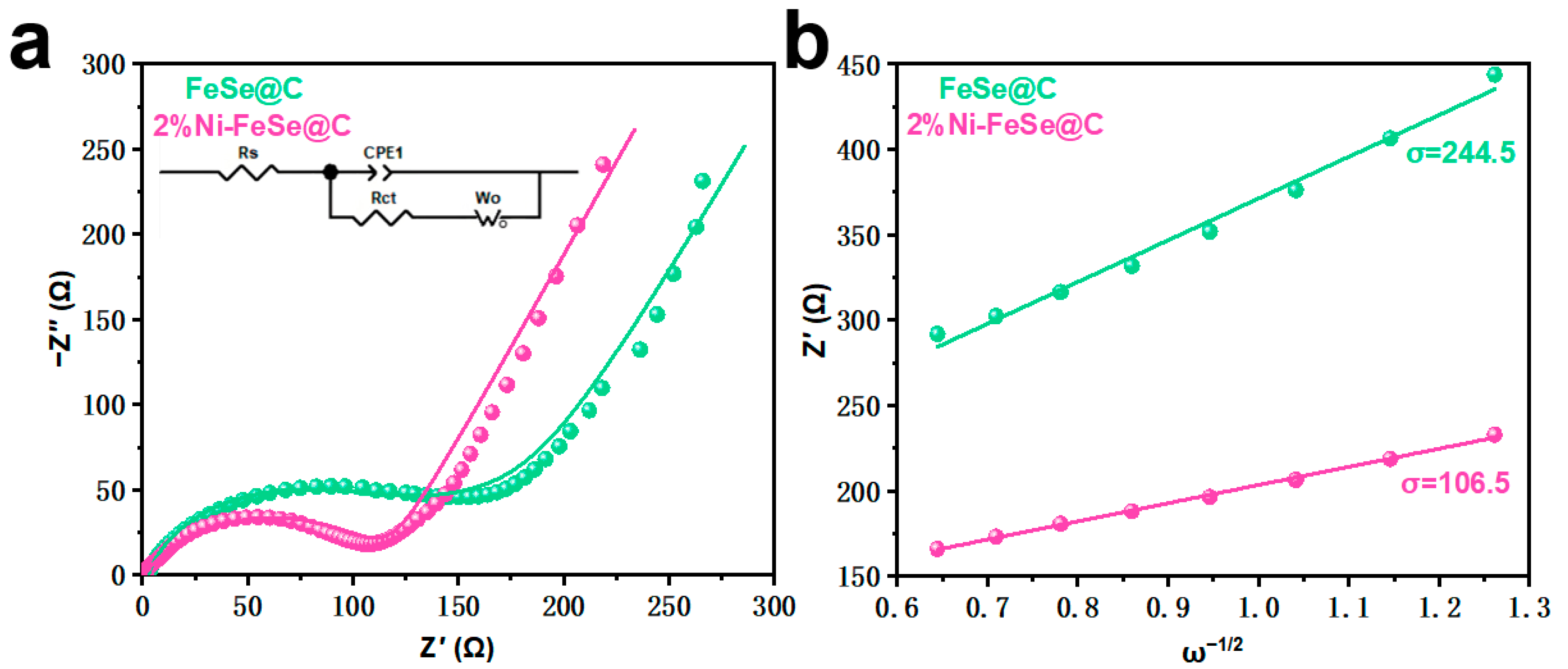
Figure 1. (a) Schematic diagram of the synthesis route for 2%Ni-FeSe@C composite; (b,c) XRD patterns of the four samples; (d) Raman spectra of FeSe@C and 2%Ni-FeSe@C.
Batteries 11 00205 g001
Figure 2. (a,b) SEM images of FeSe@C; (c,d) SEM images of 2%Ni-FeSe@C; (e,f) TEM and HRTEM images of FeSe@C; (g,h) TEM and HRTEM images of 2%Ni-FeSe@C; (i,j) mapping images of 2%Ni-FeSe@C.
Batteries 11 00205 g002
Figure 3. (a) The full XPS spectrum of FeSe@C and 2%Ni-FeSe@C; high-resolution XPS spectra of Se 3d (b), Fe 2p (c), C 1s (d), N 1s (e), and Ni 2p (f).
Batteries 11 00205 g003
Figure 5. (a,b) CV curves at various scan rates of FeSe@C and 2%Ni-FeSe@C, respectively; (c,d) relationships between the peak current and the square root of the scan rate in FeSe@C and 2%Ni-FeSe@C, respectively.
Batteries 11 00205 g005
Figure 6. (a,b) The pseudocapacitive contributions at various scan rates of FeSe@C and 2%Ni-FeSe@C; (c,d) contributions of pseudocapacitance and diffusion control at various scan rates in FeSe@C and 2%Ni-FeSe@C, respectively.
Batteries 11 00205 g006
Figure 7. (a) EIS spectra of FeSe@C and 2%Ni-FeSe@C; (b) relationship between low frequency and real resistance for FeSe@C and 2%Ni-FeSe@C.
Batteries 11 00205 g007
Figure 8. (a,b) GITT curves of FeSe@C and 2%Ni-FeSe@C; (c,d) corresponding Na+ diffusion coefficients for initial discharge and charge.
Batteries 11 00205 g008
Table 1. Electrochemical impedance parameters.
SamplesRs (Ω)Rct (Ω)σ (Ω S−0.5)D (cm2 S−1)I0 (mA cm−2)
FeSe@C3.7117.5244.55.93 × 10−922.18 × 10⁻⁴
2%Ni-FeSe@C2.9101.0106.53.13 × 10−82.54 × 10⁴
Disclaimer/Publisher’s Note: The statements, opinions and data contained in all publications are solely those of the individual author(s) and contributor(s) and not of MDPI and/or the editor(s). MDPI and/or the editor(s) disclaim responsibility for any injury to people or property resulting from any ideas, methods, instructions or products referred to in the content.

