Article

Design and Validation of Anode-Free Sodium-Ion Pouch Cells Employing Prussian White Cathodes

Department of Chemical Engineering, Faculty of Science and Engineering, Swansea University, Swansea SA1 8EN, UK
*
Authors to whom correspondence should be addressed.
Batteries 2025, 11(3), 97; https://doi.org/10.3390/batteries11030097
Submission received: 7 February 2025 / Revised: 27 February 2025 / Accepted: 1 March 2025 / Published: 4 March 2025

Abstract

:
This study investigated the impact of pouch cell design on energy density, both volumetric and gravimetric, through the development of accurate 3D models of small-format (<5 Ah) pouch cells. Various configurations were analysed, considering material properties and extrapolating expected electrochemical performance from studies on Prussian white cathodes in coin and pouch cells. This approach allowed for a rapid assessment of several performance-influencing factors, including the number of layers in the pouch cell, cathode thickness, active material percentage, and electrolyte volume. The highest calculated energy density of small-format pouch cells was shown to be 282 Wh kg−1 and 454 Wh L−1, achieved in a 3 Ah, 20-layer pouch cell. The calculations were validated using sodium-ion anode-free pouch cells utilising a Prussian white cathode in single- and few-layer format pouch cells (<0.1 Ah) cycled under a low external pressure (~200 kPa).

1. Introduction

Recently, advancements in sodium-ion batteries, particularly those utilising hard carbon anodes, have accelerated significantly. This progress is largely attributed to a deeper understanding of the anode’s structure [1], sodium-ion storage mechanisms [2,3], factors affecting the initial coulombic efficiency (ICE) [4], and the evolution of the solid electrolyte interface (SEI) [5]. Consequently, these insights have led to the development of hard carbon anodes with an improved cycle life [6] and initial capacities that rival or even surpass the 372 mAh g−1 theoretical capacity of graphite anodes used in lithium-ion batteries [7,8].
Another key factor in the resurgence of sodium-ion batteries is the development of stable, sodium-rich, high-specific-capacity cathodes. Some of the most promising are those based on Prussian blue analogues (PBAs), polyanionic materials, and layered transition metal oxides [9]. Announcements from new and long-standing battery manufacturers such as CATL, Natron Energy Inc., Faradion, Altris, Tiamat, and HiNa indicate that of these cathode categories, PBAs [10], polyanions, and layered transition metal oxides [11] have the properties required for commercialization. Both CATL and Faradion [12] have announced or demonstrated, respectively, 160 Wh kg−1 gravimetric energy density at the cell level, which is comparable to lithium iron phosphate [13]. Applying the cell-to-pack concept [14] to newly developed sodium-ion batteries would maximise energy density at the pack level (volumetric and gravimetric), demonstrating that sodium-ion batteries have great promise in applications where lithium iron phosphate is currently utilised, such as in electric vehicles and stationary storage [15]. Additionally, sodium-ion batteries demonstrate excellent performance at extremes of temperature and can be transported in a fully discharged state.
The development of current sodium-ion technology is expected to progress incrementally in terms of further increases to energy density. This will primarily be due to material development and cell design improvements, such as electrolyte volume minimization and active material percentage increases at both the cathode and anode, in addition to packaging improvements. A major stepwise improvement to the energy density of sodium-ion batteries would require a move towards a sodium metal anode, or, as is demonstrated in this work, implementing the “anode-free” concept, otherwise known as a “zero-sodium-excess” sodium metal battery (SMB) [16].
Anode-free cells differ in their assembly compared to existing rechargeable batteries by the absence of a negative electrode active material such as hard carbon or graphite. The negative electrode current collector acts as a substrate for in situ metallic plating during charge and stripping during discharge. For in situ sodium plating in particular, copper, aluminium, and zinc have shown promise as a plating substrate in sodium||substrate plating and stripping studies [17]. All sodium-ion batteries, with a host active material or plating-based anode, enable the use of low-density aluminium substrates at the negative electrode. Lithium-ion batteries require copper here due to lithium alloying with aluminium at low potentials [18]. As sodium does not exhibit this issue, aluminium would be the negative electrode of choice to increase gravimetric energy density. Among the most promising negative electrode substrates for sodium-ion anode-free cells are thin carbon coatings on aluminium [19], which, as well as having been demonstrated in sodium plating and stripping and full anode-free coin cell studies [20], are the only negative electrode substrates that have recently demonstrated cycling in full cells in cylindrical and pouch format [21]. The negative electrode within the “anode-free” cell has been studied less extensively than cathodes, especially outside of half-cell sodium plating and stripping investigations. However, we can note that a 96.5% initial coulombic efficiency (ICE) and a 99.85–99.9% average coulombic efficiency are achievable with carbon-coated aluminium substrates at moderate plating capacities. For example, Cohn et. al. reported that with a plating and stripping capacity of 2 mAh cm−2, there is a 3.5% loss in the first cycle [22]. The same authors also observed that by simply increasing the cathode loading, the first cycle losses at the anode may be reduced. We also demonstrate this relationship at low-to-moderate plating capacities in Figure S1. The relationship between areal loading and ICE has been further examined, and at extreme areal loadings of 20–40 mAh cm−2, a near-unity coulombic efficiency has been observed [23].
This present study demonstrates single- and multilayer anode-free pouch cells manufactured in our laboratory with <0.1 Ah capacity, using Prussian white cathodes, which are cycled under a low pressure. These results then informed the development of our own model for the calculation of the energy density (volumetric and gravimetric) of sodium-ion anode-free batteries made in small-format (<5 Ah) pouch cells. The in-house cell model’s usefulness is demonstrated here in its ability to guide the design of high-energy cells. We have assumed a pure aluminium substrate for simplicity, as there is negligible effect (<1%) on the energy densities calculated for aluminium vs. carbon-coated aluminium when 1-micron carbon layers are used. Prussian white has been chosen as the cathode active material due to its ability to be synthesised in a stable sodium-rich structure [24], its fast sodium-ion diffusion [25,26], and its advanced industrial development [27,28]. The electrochemical performance of sodium hexacyanoferrate (Prussian white) has been studied extensively in half cells and in full cells versus a hard carbon anode [29]. Na2Fe[Fe(CN)6] has a theoretical capacity of 170 mAh g−1 [24] and a nominal voltage of 3.1–3.2 V when adopting the rhombohedral phase [26,30]. An almost-maximum capacity is achievable if Prussian white is synthesised with low [Fe(CN)6] vacancies [31], which are sites for strongly bound water ligands to coordinate, and controlled post-synthesis and post-electrode-casting heat treatment is implemented [27,32].

2. Materials and Methods

2.1. Assembly of Pouch Cells

The feasibility of an anode-free Prussian white battery was demonstrated in single- and multilayer layer pouch cell formats. Prussian white was synthesised using a two-step method adapted from [24]. To briefly recap, Prussian blue (PB) was synthesised in the first step and washed. In the second step, monoclinic Prussian white (PW) was synthesised by the reaction of PB with a small excess of NaBH4 and subsequent washing. Rhombohedral PW was finally made by drying the washed monoclinic PW at 170 °C under a vacuum of 10−2 mBar for 20 h. The product was kept in the glovebox (MBraun ecolab < 0.1 ppm H2O and <0.1 ppm O2) to maintain the rhombohedral phase.
The single-layer cathode coating was made by mixing Super-P® and Prussian white in a Pulverisette (Fritsch™ Pulverisette 23 Mini Mill, FRITSCH GmbH—Milling and Sizing, Idar-Oberstein, Germany). After mixing the dry powders, they were transferred to a Thinky mixer (THINKY ARE-250 Mixing and Degassing Machine, Conditioning Planetary Mixer, Intertronics, Kidlington, UK), and a 6% PVDF in NMP binder solution was added to target a final proportion of materials of 8:1:1 PW–carbon–PVDF. The slurry was further mixed and adjusted with NMP to the final viscosity before the mixing was repeated. Once the target viscosity was achieved, the slurry was coated on 15 µm aluminium foil (battery-grade MTI) using an automatic film coater (MSK-AFA-II-VC-FH-MTI) and doctor blade and subsequently dried at 60 °C for 1 h. Once the initial drying was complete, the electrode was further dried at 170 °C and 10−2 mBar for 20 h before being transferred to the glovebox for use in a cell. The cathodes used in the 2- and 3-layer pouch cells were made using aqueous carboxymethylcellulose MW = 90,000–Styrene-Butadiene Rubber, [CMC:SBR (60:40 wt:wt)] binder. The final active material mass loading was 3.3–4.2 mg cm−2 for the electrodes shown in this study.
The negative electrode substrate was made using 4:1 Super-P–Carboxymethylcellulose (CMC) MW = 90,000 in a 1:1 water–ethanol solution. Once the target viscosity was achieved, the slurry was coated on 15 µm aluminium foil using an automatic film coater and doctor blade at 30 mm s−1 and dried at 60 °C for 1 h. After this, the electrode was dried at 110 °C and 10−2 mBar for 20 h before being transferred to the glovebox (Inertas custom glovebox) for use in a pouch cell.
Single-layer pouch cells were manufactured based upon the MSK-180SP die set. Cathodes with 56 mm (L) × 43 mm (W) and anodes with 58 mm (L) × 45 mm (W) dimensions were used. Aluminium tabs were welded on both electrodes, and 2 × Celgard 2320 was used. A total of 450 µL 1M NaPF6 (>99%, Alfa Aesar, Heysham, UK) in diglyme (anhydrous, 99.5%, Sigma Aldrich, Gillingham, UK) electrolyte was used in the pouch cells. The electrolyte was made with <10 ppm water content as measured by Karl Fisher using the Mettler Toledo C10SD. The electrolyte was left to soak in the pouch cell for 20 h before vacuum sealing was performed. For a pouch cell with two positive electrodes (single-side coatings) and one double-sided negative electrode, 550 µL of electrolyte was used. The optimised electrolyte volume had not been determined for these cells, as it was the purpose of this study to demonstrate feasibility with single-layer cells and to use models to examine the conditions of an array of multilayer cells.
The pouch cells were cycled using a Biologic BCS805 battery cycler under CC-CV conditions between 2 V and 3.8 V with a C/10 CV current cutoff and held in a custom jig to apply a homogeneous 200 kPa initial pressure. A pressure of 200 kPa was chosen here as it is moderate and near the optimal pressure for high initial coulombic efficiency, as demonstrated recently [33]. Indeed, lithium-ion batteries (LIBs) perform optimally when cycled at 20–200 kPa and can be fixed in packs in this pressure range, as summarised here [34]. As we had shown previously that >100 kPa was required for efficient plating and stripping to occur on the anode [35], we chose 200 kPa as a commercially relevant and functional compromise. Further research is needed to look at pressure effects in sodium-ion anode-free cells, in parallel to that carried out on lithium-ion anode-free cells [36]. The pressure dependency demonstrated in anode-free cells is greater than that shown in standard LIBs due to the extreme dependence of the anode plating and stripping on pressure.

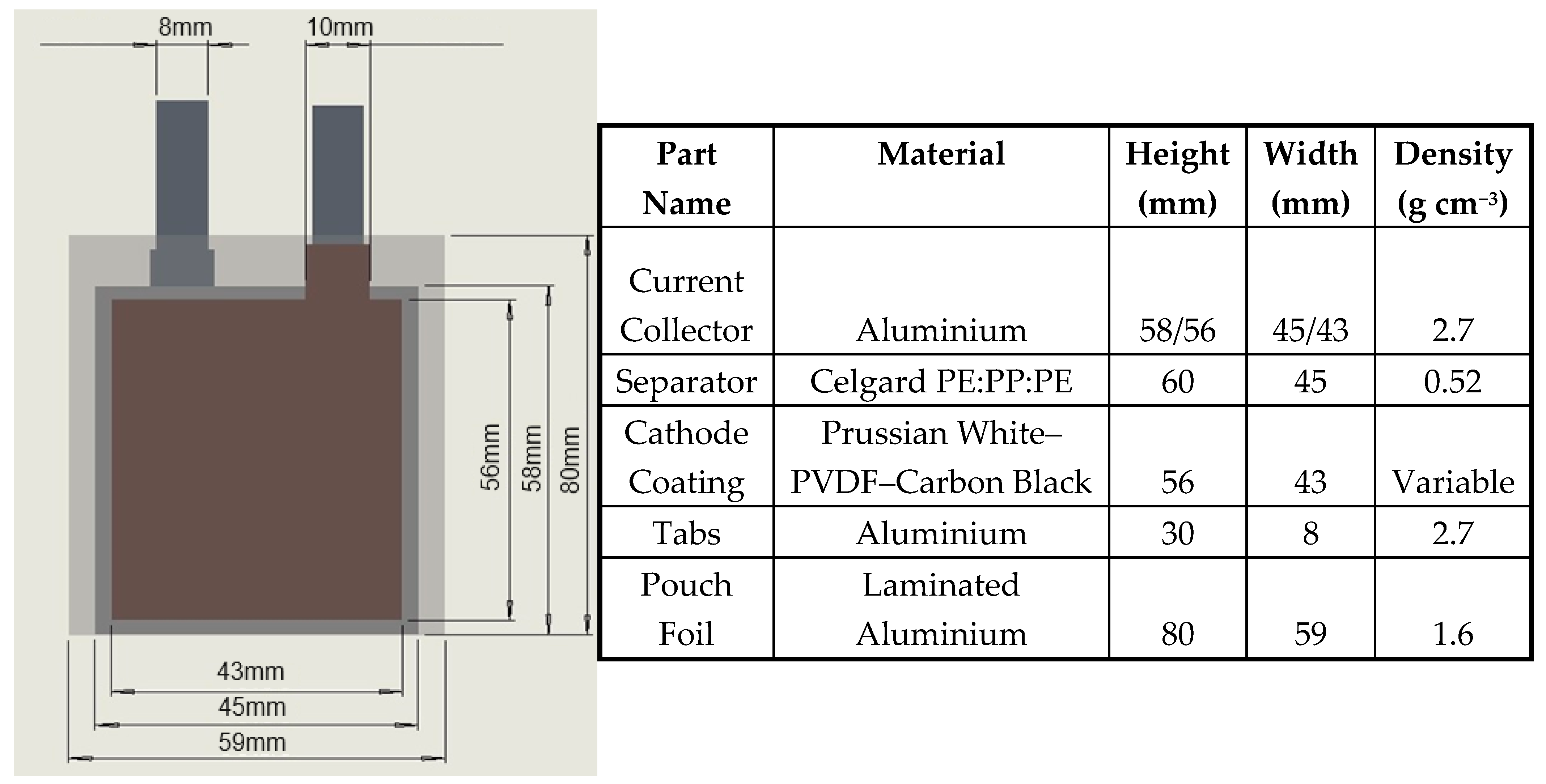
2.2. Building the Pouch Cells: 3D Model and Material Properties

To extrapolate the performance of the demonstrated pouch cells to many-layer cells, a pouch cell model was built. In building the models used in this study, the dry mass/volume, wet mass/volume, and electrochemical performance had to be realistically considered. With this goal in mind, the following approach was taken. Firstly, small-format sodium-ion anode-free pouch cells (up to 40 cathode layers and <5 Ah) were first modelled in 3D using SOLIDWORKS and later a custom cell calculator to enable the rapid assessment of parameters to be carried out.
The mass and volume of all dry components of the pouch cell required for operation were calculated with accurate material density and cell dimensions for small-format R&D pouch cells. A list of the cell components and parameters is shown in Figure 1, along with a basic illustration of the cell design with a translucent pouch material to enable the visualisation of the electrodes within. The cell format is based around the standard die set supplied by MTI with the MSK-180SP for R&D-scale manufacturing and considers the separator to be z-stacked tightly around the electrodes. The porosity of the separator and the cathode coating is considered in the cell calculations as follows: for the separator, the porosity is known from the manufacturer, Celgard, to be 39%; for the cathode coating, a constant 25% porosity is used for all considerations below. It must be noted that 25% porosity was chosen as a reasonable average based on lithium-ion cathode castings for energy cells [37,38]. However, the optimal porosity for the capacity, power, and cycle life of Prussian white is not known. The value that we use here is only slightly lower than that used in previous Prussian white studies [27]. Studies on Prussian white usually do not refer to the final density or porosity of the electrodes, which are important to consider when calendaring. F. M. Maddar et al. [27] mention a target density of 1.5 g cm−3 for a 93% PW cathode using CMC:SBR and carbon to achieve 30% porosity. On initial inspection, given that Prussian blue has a material density of 1.8 g cm−3 [39], a final coating density of 1.5 g cm−3 does not seem possible with a 30% porosity. To explain this, we measured the crystal density via XRD of the sodium-rich rhombohedral Prussian white used in this study, revealing it to be 2.3 g cm−3. The higher density of Prussian white vs. Prussian blue is due to the reduced cell volume and the higher sodium content per unit cell.

2.3. Cell Model Calculations

For the calculations of cell parameters, Python software (Solid works 2024) was written. The source code is available on Github. The software consists of 4 modules: (i) app.py, the main application file containing the Streamlit interface and logic; (ii) cell_components.py, containing classes for various cell components and methods for all the calculations; (iii) graphs.py, generating and plotting energy density data; and (iv) materials.py, a dictionary of material properties. The software was constructed following object-orientated programming; i.e., the cell components are defined as classes (Electrode, Separator, Electrolyte, etc.) with key attributes and methods. The required input parameters are collected through a graphical user interface (GUI) built with the Streamlit package. The inputs are passed as the component attributes, and the cell class is constructed from the component objects. On initialization, methods for the calculation of energy density, etc., are run, allowing for the real-time display of results upon changing inputs. The resulting cell object is presented as a table and can be downloaded in .csv format for further analysis. Additionally, the software allows us to plot graphs of energy density vs. one variable input (cathode coating thickness, number of layers, etc.). The results, again, can be downloaded as a .csv table.
The cell modelling starts by defining the electrodes. Key parameters such as chemistry, capacity, and dimensions can be provided by the user. To accurately compute the mass and volume of the electrode, it is crucial to know the density of the coated composite (active material, conductive carbon, and binder). For this crystal (true) density of each item, their respective mass ratio and electrode porosity are taken. To calculate the gravimetric and volumetric energy density of the final wet cell, the volume and mass of the electrolyte need to be considered. In this type of battery, 1 M NaPF6 in diethyleneglycol dimethyl ether (diglyme) represents a promising candidate due to its plating and stripping anode performance and compatibility with Prussian white [27,40]. Therefore, the density of this electrolyte (herein measured as ~1.15 g cm−3) is considered along with its volume in comparison to the total pore volume within the dry cell. The electrolyte has been considered in this way in lithium-ion pouch cells previously, and it is a useful method for considering the minimum electrolyte required to soak the total cell porosity and maximise energy density [41]. For lithium-ion large-format pouch cells, an electrolyte filling level between an exact filling of available pores and a 20% electrolyte excess has been found to be optimal, balancing energy density and cycle life [41]. For electrolyte–pore–volume ratios of greater than unity, i.e., where there is more electrolyte than the pores available to contain it within the separator and cathode coating, only the electrolyte volume that constitutes excess to the pores contributes to the total cell volume in volumetric energy density (Wh L−1) calculations. However, the electrolyte mass within and outside of the pores contributes to gravimetric energy density (Wh L−1) calculations. In this way, the electrolyte contribution may be treated accurately from a gravimetric and volumetric perspective. In a similar manner, calculations are performed for the anode-free configuration. To accurately estimate the volumetric energy density, the cell volume is considered in the charged state, i.e., when all the sodium is plated on the negative substrate. However, since all this sodium effectively comes from the cathode, it is already included in the mass of the cell, and therefore in the calculation of gravimetric energy density, the mass of plated sodium is subtracted from the total mass.

3. Results and Discussion

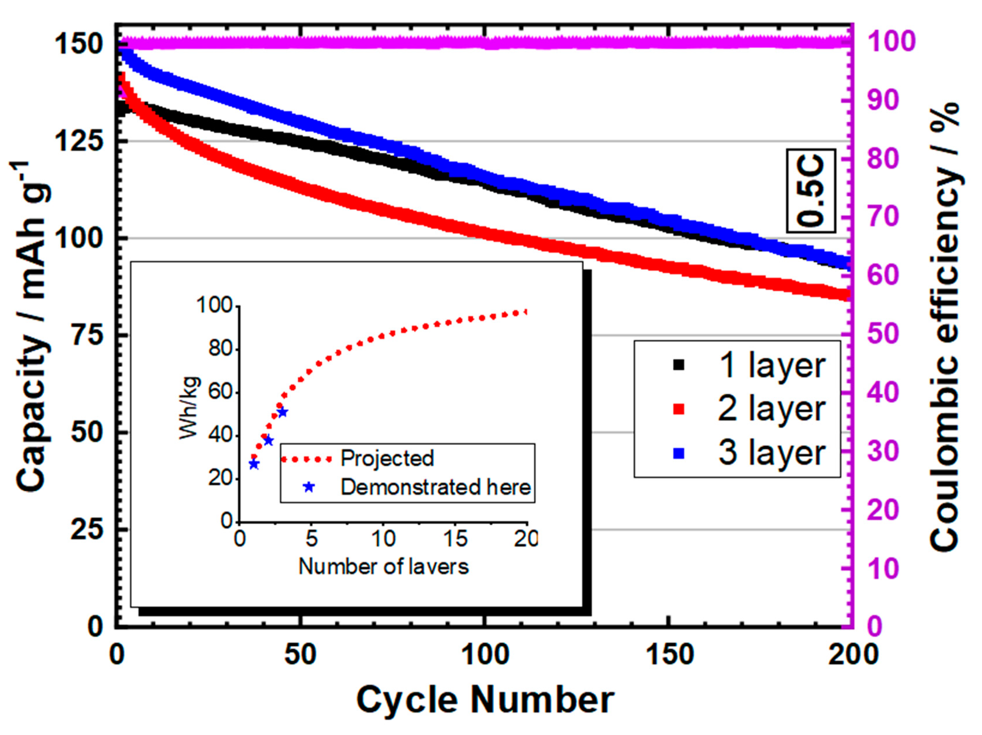
3.1. Pouch Cell Results

Figure 2 shows the results for three sodium-ion anode-free pouch cells based on 80% active material Prussian white positive electrodes, cycled at 0.5C. All are truly anode-free in that they have zero sodium metal at the negative electrode substrate upon assembly, and therefore the negative–positive areal capacity (N:P) ratio is zero. The 1-layer cell contains a double-sided anode (both sides of aluminium foil coated with a carbon nucleation layer) bracketed by two single-sided cathodes and the use of NMP:PVDF binder. The 2-layer cell consists of 2 double-sided cathodes and 1 double-sided negative electrode in the centre, bracketed by 2 single-sided negative electrodes. The 3-layer cell is made as per the two-layer cell but with an extra double-sided negative and positive electrode. The 2- and 3- layer cells use cathode electrodes made with an aqueous CMC:SBR (60:40) slurry. The initial discharge capacity is between 134 and 150 mAh g−1. The initial capacity and capacity fade match those of a PW||Na coin cell made with the same electrode casting batch as the single-layer pouch cell (Figure S6). The variation in performance between the pouch cells shown reflects some variation between cathode casting batches and differences between NMP:PVDF and CMC:SBR. CMC:SBR exhibits a higher initial capacity and more rapid initial fade, contrary to PVDF:NMP. These differences are noted as occurring early in the cycling of these pouch cells, so they could be related to the structural stabilisation of the electrodes. However, these comments are not intended to represent a thorough analysis of the casting differences between the aqueous and non-aqueous processing of Prussian white electrodes. It is also noted that the rate of fade of these anode-free pouch cells is typical for rhombohedral Prussian white cathodes. For example, in reference [31], the capacity loss is 10% within the first 50 cycles in a PW||Na half-cell, identical to the rate of fade demonstrated here, shown in Figure S6, in anode-free format.
The initial coulombic efficiency (ICE) is 91%, which is equal to that of the ICE of a plating and stripping half-cell using carbon-coated aluminium, indicating that the first cycle loss is largely due to the anode. The average coulombic efficiency excluding the first cycle is 99.8%. The reduction in capacity from the theoretical value is likely due to a small number of defects in the PW crystal structure and/or a small sodium deficiency. During cycling, cells demonstrate increasing peak-to-peak separation in dQ/dV analysis (Figure S2), mainly in the lower voltage plateau. In the first cycles, the proportion of the discharge capacity attributed to the lower (2.95 V) voltage plateau is slightly greater than the higher (3.27 V) voltage plateau. By 200 cycles, the situation is reversed and the higher voltage discharge plateau accounts for most of the capacity. This indicates that some of the fade is accounted for by the preferential loss of high-spin iron–nitrogen (Fe-NHS) sites [42] within the Prussian white active material. The optimisation of active material and pouch cells for extended cycle life will be the focus of future work.
To compare the anode-free results to the model detailed below, the energy density of the 1-, 2-, and 3- layer pouch cells was calculated from the initial discharge capacity and weight, as pictured for one cell in Figure S4. Herein, the single-layer pouch cell weighed 2.84 g (whole-cell mass), with a 3.1 V nominal voltage, resulting in 77.5 mWh. This results in a 27 Wh kg−1 cell. The three-layer cell exhibited an energy density of 51 Wh kg −1. Comparing both manufactured cells to the model-predicted energy density under identical assembly conditions results in expected energy densities of 30 and 58 Wh kg−1, respectively. The lower energy density here is explained by the extra electrolyte used to make these pouch cells (+0.3 mL) and to ensure the complete wetting of electrodes. This excess reduces as the layers increase and the dead cell volume is reduced as a proportion of the active volume. The extrapolation of this performance to larger cells is discussed in more detail in the next section. However, the expected energy density is shown in the inset of Figure 2 (red-dashed) upon increasing the number of layers from 3 to 20, based upon the cathode coating thickness (~50 micron), 80% active material, and 30% electrode porosity used in the manufactured cells (blue stars). This is noted here as experimental validation for the model used and the design parameters considered in the following section.
It is worth comparing these results with the limited literature on anode-free sodium-ion cells that exist in pouch format using various cathodes and negative electrode substrate solutions. There are many examples of anode-free coin cells using NVP-based cathodes [17,22,43,44,45,46,47,48,49] but few demonstrating pouch cells. For example, Rong Zhuang et al. developed a Fluorinated porous framework to modify the anodic substrate and improve sodium plating [50]. The modified anode enabled the manufacture of a sodium-ion anode-free pouch cell with improved performance over the unmodified substrate, copper. It must be noted that most of the results in that study included excess sodium metal (N/P 1.5–0.5), whereas a true anode-free cell requires an N/P ratio of 0 in a discharged state. The presented supplementary information demonstrates such a cell with an average CE of 98.7% and a specific capacity of 61.2 mAh g−1 after 50 cycles, corresponding to a capacity retention of 77.9%. The referenced pouch cell was made with a glass fibre separator in contrast to the Celgard 2320 separator used within the present study, and therefore dendrite issues may have been masked. Wu Zhang et al. demonstrated another NVP-based anode-free pouch cell using a copper phosphide nanowire grown on a copper negative electrode [49]. Here, an initial 30 mAh pouch cell rapidly lost half its capacity to reach 15 mAh after 25 cycles. However, it was then stable for 200 cycles with minimal fade. The separator type was not given. The effective plating and stripping that occurred in this solution could be the result of an increasing effective surface area/decreased effective current density. In this way, this approach may improve the performance of sodium-ion plating and stripping through the same mechanism as other approaches using carbon layers.
Anode-free sodium-ion full coin cells were demonstrated in a previous study using a layered metal oxide cathode Na[Cu1/9Ni2/9Fe1/3Mn1/3]O2 and a thin graphitic or amorphous carbon coated on an aluminium negative electrode [21]. This study utilised thicker carbon coatings than those made in our work. In the referenced study, by Yuqi Li et al., ~400 µg cm−2 coating of carbon was used, which resulted in 4–8 µm coating thicknesses. In another study with a similar substrate to ours, Cohn et al. demonstrated an NVP-based anode-free battery in coin cell format using a carbon black-coated aluminium that was ~200 µg cm−2 [22]. This layer enabled the homogeneous nucleation of sodium. Another study by Cohn et. used a 400 µg cm−2 thin carbon layer, in which a presodiated pyrite cathode was cycled against Al@C in coin cell format for 40 cycles with a capacity of 400 mAh g−1 [19].
We have utilised <100 µg cm−2 carbon coatings, as we found higher capacity fade with thicknesses between 200 and 400 µg cm−2 and cells that, following the initial charge (sodium plating), exhibited erratic discharge (sodium stripping) when using negative electrodes with bare aluminium or copper. Therefore, for our work, <100 µg cm−2, ~1 µm Super-P coatings seemed optimal and were used, which had the added benefit of a negligible mass and volume contribution to the final cell in comparison to thicker coatings. The reason that higher mass loadings of carbon did not work in our experience is unclear and requires further investigation. We suspect that the total electrochemically active surface area plays a role, as our study uses thin, uncalendared electrodes and Yuqi Li et al. utilised thicker but calendared electrodes [21]. We hypothesise that thicker coatings of carbon at negative electrodes, be they calendared or uncalendared, exhibit greater anodic SEI formation, which consumes the limited sodium within anode-free cells. This will be the focus of a future investigation to optimise the negative electrode and electrolyte, as they are critical in developing functioning anode-free sodium-ion batteries.
It must be noted that in the recent sodium-ion anode-free review by Yujie Chen et al., many purportedly anode-free sodium-ion batteries are plotted, with their energy density and cycle life referenced [16]. However, most of these are not anode-free and utilise, for example, sodium metal-electroplated anodes. What we have discussed are studies that either focus on true anode-free cells or include anode-free results as an aside to the main work. Works by both Siwu Li et al. [46] and Huihua Li et al. [44] use limited excess sodium metal to make low N/P ratio cells in the bulk of their investigation. However, they do explore the completely anode-free concept of a zero N/P battery in coin cell format. Again, an NVP cathode is used, and for both studies, the precycling of the anode is used to form a stable SEI before assembly. This could be due to the larger areal loading of carbon (1.2–1.5 mg−2) used in their study compared to those studies that do not need pre-cycling in this way.
An interesting approach to developing a carbon nucleation layer was taken by Min Eui Lee et al., who also demonstrated the benefits of thin carbon layers in nucleating sodium plating for anode-free cells [51]. In their study, a 100 nm carbonaceous thin film was made by first spin-coating silk fibroin on to copper before pyrolysis at 800 °C. This highly conformal carbon coating exhibited improved plating and stripping vs. copper and could cycle in anode-free format in coin cells against a Na1.5VPO4.8F0.7 cathode with a 90 mAh g−1 capacity for 30 cycles. A similar approach was taken by Tianjiao Li et al., whereby an oxygen-containing carbonised coconut framework was made for the negative electrode and exhibited only 4% capacity loss in a fully anode-free coin cell against an NVP cathode [45].
There have been some other demonstrations of efficient sodium plating and stripping that have been extended to anode-free cells in coin cell format. For example, remarkable stability has been demonstrated using NVP against copper utilising a formate interlayer [47]. It has also been shown that carbon cloth decorated with silver nanoparticles may exhibit stable half- and full-cell anode-free cycling vs. a MnFe Prussian white cathode [52].
The carbon-coated aluminium layers that we demonstrate in this study have potential as a commercially relevant negative electrode for sodium-ion anode-free batteries due to their low complexity and manufacturing costs.

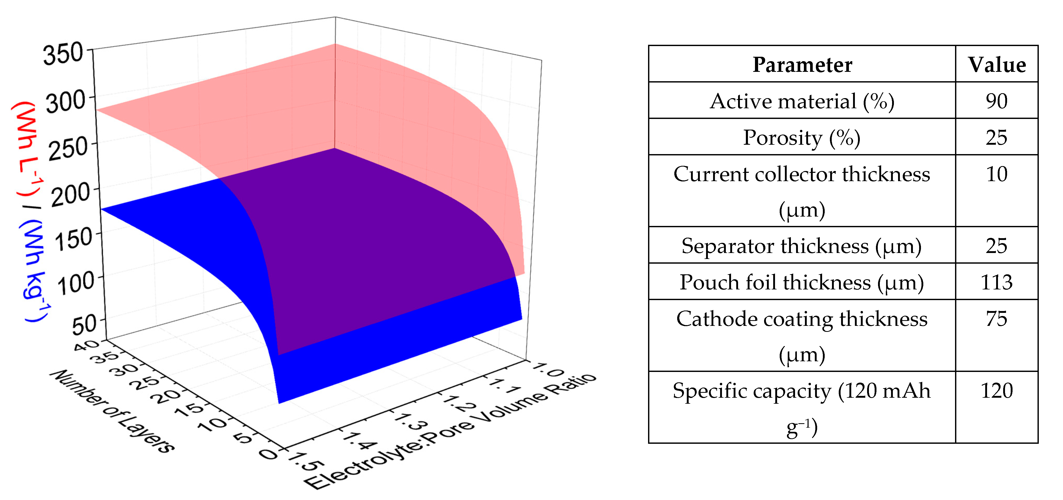
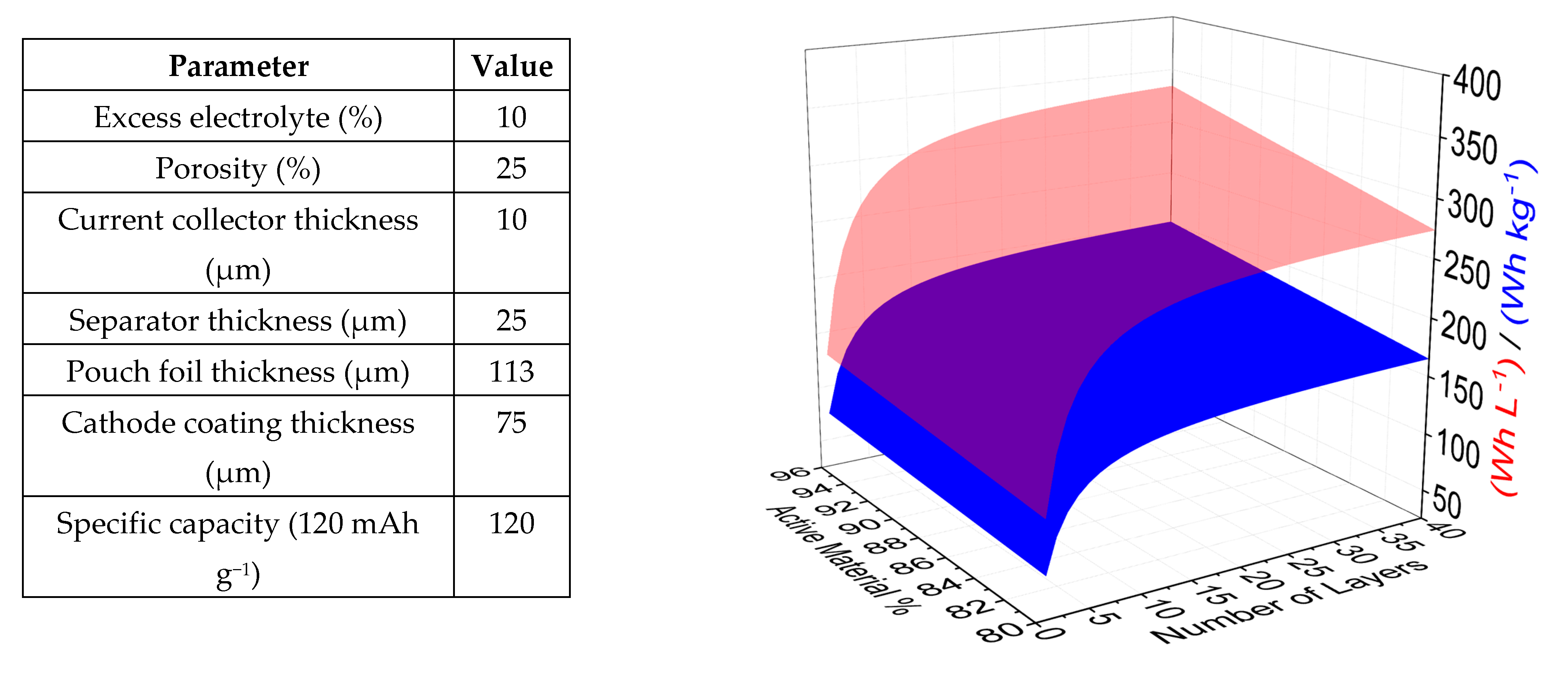
3.2. Modelling Expected Multilayer Pouch Cell Performance

To understand the potential of anode-free sodium-ion pouch cells employing Prussian white cathodes, we extrapolated the validated performance of single-layer pouch cells to multiple layers using models. Our in-house cell model operates by setting several parameters in the manufacture constant and varying a parameter of interest to see its effect on energy density, capacity, energy, etc. Figure 3 shows the expected energy density for cells made with various electrolyte volumes and number of layers. The fixed conditions for each graph are shown. As expected, there is an initial exponential increase in energy density when the number of layers is increased in the cell, as the active components contribute a larger percentage of the final cell mass and volume. This increase levels off between 20 and 40 layers, as the active components increasingly contribute to the total mass and volume percentage. The effect of electrolyte volume on energy density is more subtle and linear compared to the number of layers, as only low, commercially relevant electrolyte volumes are considered here; i.e., high excess electrolyte volumes are not considered even though they may be necessary for single-layer pouch cells to function. The maximum energy density modelled under these conditions for a 40-layer 2.6 Ah cell is 191 Wh kg−1 and 318 Wh L−1.
The effect of the number of layers on the final cell properties is also shown in Figure 4. However, in this figure, the second axis now shows an active material percentage in the 80–96% range, which covers a range from laboratory-scale to commercially applicable. A 1.1:1 electrolyte-to-pore-volume ratio was maintained in the models here, as this would just wet the pores of the cell and was shown to be in the optimal range for lithium-ion pouch cells [41]. Although the optimal electrolyte volume is not known for sodium-ion anode-free batteries experimentally, we thought that the choice of a small electrolyte volume excess to ensure pore filling was prudent. Under the conditions demonstrated here, the maximum predicted energy density for a 40-layer 2.8 Ah cell is 202 Wh kg−1 and 335 Wh L−1.
In Figure 5, the conditions modelled are developed to cover more commercially applicable scenarios whilst still covering cells that could be manufactured in an advanced battery manufacturing research institution. For the final range of conditions that are plotted in Figure 4, the number of layers was fixed to 20, to enable the simultaneous illustration of the active material capacity and variable active material percentage in pouch cells. Here, it is shown that 282 Wh kg−1 and 454 Wh L−1 can be achieved in a 3 Ah 20-layer pouch cell using a 125-micron coating and 96% active material. Commercial electrodes rarely exceed 100 µm [53], and therefore our calculations only included thicknesses 25 µm above this range.
Additional small increases could be made to the energy density (both volumetric and gravimetric), as demonstrated in Figure 5, with energy density increases shown in comparison to the highest value in Figure 4 (282 Wh kg−1 and 454 Wh L−1). Particularly, the following points are made:
  • A reduced separator thickness (from 25 µm to 10 µm) would decrease the volume and weight of the cell due to the combined effect of the thickness and the lower amount of electrolyte required to wet the separator pores. However, mechanical stability and fire resistance would become increasingly problematic (+19 Wh kg−1/41 Wh L−1);
  • Pouch foil thickness may be reduced (from 113 µm to 68 µm) (+6 Wh kg−1/9 Wh L−1);
  • Ultrathin aluminium (6 µm) or aluminium/PET composite films (8 µm) as substrate materials for both electrodes should be investigated in place of the 10-micron aluminium used here (+21 Wh kg−1/10 Wh L−1).
There are minimal experimental data in the literature that specifically include sodium-ion anode-free pouch cell results that can be used to benchmark the calculated data produced in this study. However, similar batteries have been produced in pouch cell format, the most developed being the layered oxide-based Na[Cu1/9Ni2/9Fe1/3Mn1/3]O2 sodium-ion anode-free pouch cell demonstrated by Yuqi et al. [21]. Here, a 200 Wh kg−1 energy density in a 0.9 Ah cylindrical cell is achieved when using a 94.5% active material, high mass loading, lean electrolyte. Although a different cathode is used, the nominal voltage is near Fe-Fe Prussian white at 3 V and therefore corroborates the predicted performances displayed here for PW anode-free cells. We reference this work as an external validation of the model, in addition to the internal validation that we demonstrated using our own manufactured pouch cells. Other sodium-ion anode-free studies that could be considered for model validation were at a lower so-called technology readiness level (TRL) and were discussed in reference to our experimental work above.

4. Conclusions

In our work, we have, for the first time, according to our knowledge, demonstrated Prussian white operating in an anode-free format in pouch cells at low applied pressure, with no electrode pre-cycling or pre-sodiation [48] or the electroplating of a thin sodium layer (N:P = 0). This is in part enabled due to the thin negative electrode coatings, which offer efficient plating and stripping of sodium, as shown in the work presented here and in the previous literature discussed above. Although there are several solutions available for efficient sodium plating and stripping that have been, or could be, applied to the anode-free concept, we propose thin carbon layers as a simple industrially applicable solution for Prussian white anode-free pouch cells. These initial results are extrapolated with pouch cell energy density calculations under an array of experimental conditions, which outline the path for multilayer cell development, which will comprise the next stage of our research. In addition, optimised cathode synthesis and casting will be developed to demonstrate improved cyclability in anode-free PW cells under moderate pressure (<200 kPa) conditions.

Supplementary Materials

The following supporting information can be downloaded at: https://www.mdpi.com/article/10.3390/batteries11030097/s1, Figure S1. Initial coulombic efficiency as a function of the plating capacity. Sodium plating and stripping over a carbon-coated aluminium substrate in coin cell format. The current applied is double the plating capacity for a duration of 30 min; i.e., 0.5 mAh cm−1 = 1 mA cm−1 for 30 min. Figure S2. Left, differential capacity for selected cycles of a single-layer pouch cell. Right, charge discharge profiles for the same selected cycles. Figure S3. XRD profiles of (a) Monoclinic PW and (b) Rhombohedral PW. A small amount of NaCl impurity is evident at 28 degrees, as discussed previously in DOI: 10.1021/acsami.0c22032. Figure S4. SEM images of (a) PBA and (b) Rhombohedral PW vacuum-dried at 170 °C. Figure S5. The pouch cell that was used for comparison for modelling purposes. Figure S6. Comparison between an anode-free pouch cell (Black) and a PW||Na half-cell (green) from the same electrode batch, illustrating the similar rate of capacity fade in these cell formats.

Author Contributions

A.W.—Development of the cell model, pouch cell assembly, cycling, writing of the manuscript. M.O.—Cathode slurry formulation and casting, pressure jig design for pouch cells, development of the cell model. S.K.—Prussian white synthesis. N.R.—Negative electrode slurry formulation and casting. M.H.—Negative electrode plating and stripping studies. O.O.—Initial Solidworks calculator. Z.T.—Material density measurements. S.M.—Project idea and planning. All authors have read and agreed to the published version of the manuscript.

Funding

This project was funded by Enserv Ltd.

Data Availability Statement

All cell data in this study are available upon request. The cell calculator developed has been made available online at https://usablewatts.com/webtools/wattcell/, accessed on 1 January 2025. The source code for the cell calculator is available at https://github.com/sirlod/WattCell/tree/v0.1, accessed on 1 January 2025.

Conflicts of Interest

Marcin Orzech is the owner of Wattcraft Ltd., who manufacture and sell the pressure jigs used in this study.

References

  1. Dou, X.; Hasa, I.; Saurel, D.; Vaalma, C.; Wu, L.; Buchholz, D.; Bresser, D.; Komaba, S.; Passerini, S. Hard carbons for sodium-ion batteries: Structure, analysis, sustainability, and electrochemistry. Mater. Today 2019, 23, 87–104. [Google Scholar] [CrossRef]
  2. Alvin, S.; Yoon, D.; Chandra, C.; Cahyadi, H.S.; Park, J.-H.; Chang, W.; Chung, K.Y.; Kim, J. Revealing sodium ion storage mechanism in hard carbon. Carbon 2019, 145, 67–81. [Google Scholar] [CrossRef]
  3. Stevens, D.A.; Dahn, J.R. The Mechanisms of Lithium and Sodium Insertion in Carbon Materials. J. Electrochem. Soc. 2001, 148, A803. [Google Scholar] [CrossRef]
  4. Wan, Y.; Liu, Y.; Chao, D.; Li, W.; Zhao, D. Recent advances in hard carbon anodes with high initial Coulombic efficiency for sodium-ion batteries. Nano Mater. Sci. 2023, 5, 189–201. [Google Scholar] [CrossRef]
  5. Li, K.; Zhang, J.; Lin, D.; Wang, D.-W.; Li, B.; Lv, W.; Sun, S.; He, Y.-B.; Kang, F.; Yang, Q.-H.; et al. Evolution of the electrochemical interface in sodium ion batteries with ether electrolytes. Nat. Commun. 2019, 10, 725. [Google Scholar] [CrossRef] [PubMed]
  6. Bai, P.; He, Y.; Xiong, P.; Zhao, X.; Xu, K.; Xu, Y. Long cycle life and high rate sodium-ion chemistry for hard carbon anodes. Energy Storage Mater. 2018, 13, 274–282. [Google Scholar] [CrossRef]
  7. Zhao, C.; Wang, Q.; Lu, Y.; Li, B.; Chen, L.; Hu, Y.-S. High-temperature treatment induced carbon anode with ultrahigh Na storage capacity at low-voltage plateau. Sci. Bull. 2018, 63, 1125–1129. [Google Scholar] [CrossRef]
  8. Sun, N.; Liu, H.; Xu, B. Facile synthesis of high performance hard carbon anode materials for sodium ion batteries. J. Mater. Chem. A 2015, 3, 20560–20566. [Google Scholar] [CrossRef]
  9. Peng, C.; Xu, X.; Li, F.; Xi, L.; Zeng, J.; Song, X.; Wan, X.; Zhao, J.; Liu, J. Recent Progress of Promising Cathode Candidates for Sodium-Ion Batteries: Current Issues, Strategy, Challenge, and Prospects. Small Struct. 2023, 4, 2300150. [Google Scholar] [CrossRef]
  10. Nielsen, I.; Dzodan, D.; Ojwang, D.O.; Henry, P.F.; Ulander, A.; Ek, G.; Häggström, L.; Ericsson, T.; Boström, H.L.B.; Brant, W.R. Water driven phase transitions in Prussian white cathode materials. J. Phys. Energy 2022, 4, 044012. [Google Scholar] [CrossRef]
  11. Bauer, A.; Song, J.; Vail, S.; Pan, W.; Barker, J.; Lu, Y. The Scale-up and Commercialization of Nonaqueous Na-Ion Battery Technologies. Adv. Energy Mater. 2018, 8, 1702869. [Google Scholar] [CrossRef]
  12. Rudola, A.; Rennie, A.J.R.; Heap, R.; Meysami, S.S.; Lowbridge, A.; Mazzali, F.; Sayers, R.; Wright, C.J.; Barker, J. Commercialisation of high energy density sodium-ion batteries: Faradion’s journey and outlook. J. Mater. Chem. A 2021, 9, 8279–8302. [Google Scholar] [CrossRef]
  13. Li, J.; Ma, Z.-F. Past and Present of LiFePO4: From Fundamental Research to Industrial Applications. Chem 2019, 5, 3–6. [Google Scholar] [CrossRef]
  14. Pampel, F.; Pischinger, S.; Teuber, M. A systematic comparison of the packing density of battery cell-to-pack concepts at different degrees of implementation. Results Eng. 2022, 13, 100310. [Google Scholar] [CrossRef]
  15. Abraham, K.M. How Comparable Are Sodium-Ion Batteries to Lithium-Ion Counterparts? ACS Energy Lett. 2020, 5, 3544–3547. [Google Scholar] [CrossRef]
  16. Chen, Y.; Ye, C.; Zhang, N.; Liu, J.; Li, H.; Davey, K.; Qiao, S.-Z. Prospects for practical anode-free sodium batteries. Mater. Today 2024, 73, 260–274. [Google Scholar] [CrossRef]
  17. Dahunsi, O.J.; Gao, S.; Kaelin, J.; Li, B.; Abdul Razak, I.B.; An, B.; Cheng, Y. Anode-free Na metal batteries developed by nearly fully reversible Na plating on the Zn surface. Nanoscale 2023, 15, 3255–3262. [Google Scholar] [CrossRef]
  18. Wang, H.; Tan, H.; Luo, X.; Wang, H.; Ma, T.; Lv, M.; Song, X.; Jin, S.; Chang, X.; Li, X. The progress on aluminum-based anode materials for lithium-ion batteries. J. Mater. Chem. A 2020, 8, 25649–25662. [Google Scholar] [CrossRef]
  19. Cohn, A.P.; Muralidharan, N.; Carter, R.; Share, K.; Pint, C.L. Anode-Free Sodium Battery through in Situ Plating of Sodium Metal. Nano Lett. 2017, 17, 1296–1301. [Google Scholar] [CrossRef]
  20. Mazzali, F.; Orzech, M.W.; Adomkevicius, A.; Pisanu, A.; Malavasi, L.; Deganello, D.; Margadonna, S. Designing a High-Power Sodium-Ion Battery by in Situ Metal Plating. ACS Appl. Energy Mater. 2019, 2, 344–353. [Google Scholar] [CrossRef]
  21. Li, Y.; Zhou, Q.; Weng, S.; Ding, F.; Qi, X.; Lu, J.; Li, Y.; Zhang, X.; Rong, X.; Lu, Y.; et al. Interfacial engineering to achieve an energy density of over 200 Wh kg−1 in sodium batteries. Nat. Energy 2022, 7, 511–519. [Google Scholar] [CrossRef]
  22. Cohn, A.P.; Metke, T.; Donohue, J.; Muralidharan, N.; Share, K.; Pint, C.L. Rethinking sodium-ion anodes as nucleation layers for anode-free batteries. J. Mater. Chem. A 2018, 6, 23875–23884. [Google Scholar] [CrossRef]
  23. Ma, B.; Lee, Y.; Bai, P. Dynamic Interfacial Stability Confirmed by Microscopic Optical Operando Experiments Enables High-Retention-Rate Anode-Free Na Metal Full Cells. Adv. Sci. 2021, 8, 2005006. [Google Scholar] [CrossRef]
  24. Lim, C.Q.X.; Tan, Z.-K. Prussian White with Near-Maximum Specific Capacity in Sodium-Ion Batteries. ACS Appl. Energy Mater. 2021, 4, 6214–6220. [Google Scholar] [CrossRef]
  25. Yuan, M.; Liu, H.; Ran, F. Fast-charging cathode materials for lithium & sodium ion batteries. Mater. Today 2023, 63, 360–379. [Google Scholar] [CrossRef]
  26. Wang, L.; Song, J.; Qiao, R.; Wray, L.A.; Hossain, M.A.; Chuang, Y.-D.; Yang, W.; Lu, Y.; Evans, D.; Lee, J.-J.; et al. Rhombohedral Prussian White as Cathode for Rechargeable Sodium-Ion Batteries. J. Am. Chem. Soc. 2015, 137, 2548–2554. [Google Scholar] [CrossRef]
  27. Maddar, F.M.; Walker, D.; Chamberlain, T.W.; Compton, J.; Menon, A.S.; Copley, M.; Hasa, I. Understanding dehydration of Prussian white: From material to aqueous processed composite electrodes for sodium-ion battery application. J. Mater. Chem. A 2023, 11, 15778–15791. [Google Scholar] [CrossRef]
  28. Peng, J.; Zhang, W.; Liu, Q.; Wang, J.; Chou, S.; Liu, H.; Dou, S. Prussian Blue Analogues for Sodium-Ion Batteries: Past, Present, and Future. Adv. Mater. 2022, 34, 2108384. [Google Scholar] [CrossRef]
  29. Ma, H.; Jiang, M.; Hou, Z.; Li, T.; Zhang, X.; Gao, Y.; Peng, J.; Li, Y.; Wang, J.-G. Medium-mediated high-crystalline Prussian blue toward exceptionally boosted sodium energy storage. Energy Storage Mater. 2024, 70, 103411. [Google Scholar] [CrossRef]
  30. Ericsson, T.; Häggström, L.; Ojwang, D.O.; Brant, W.R. Investigation of Valence Mixing in Sodium-Ion Battery Cathode Material Prussian White by Mössbauer Spectroscopy. Front. Energy Res. 2022, 10, 909549. [Google Scholar] [CrossRef]
  31. Brant, W.R.; Mogensen, R.; Colbin, S.; Ojwang, D.O.; Schmid, S.; Häggström, L.; Ericsson, T.; Jaworski, A.; Pell, A.J.; Younesi, R. Selective Control of Composition in Prussian White for Enhanced Material Properties. Chem. Mater. 2019, 31, 7203–7211. [Google Scholar] [CrossRef]
  32. Hartmann, L.; Deshmukh, J.; Zhang, L.; Buechele, S.; Metzger, M. Reversing the Chemical and Structural Changes of Prussian White After Exposure to Humidity to Enable Aqueous Electrode Processing for Sodium-ion Batteries. J. Electrochem. Soc. 2023, 170, 030540. [Google Scholar] [CrossRef]
  33. Sayahpour, B.; Li, W.; Bai, S.; Lu, B.; Han, B.; Chen, Y.-T.; Deysher, G.; Parab, S.; Ridley, P.; Raghavendran, G.; et al. Quantitative analysis of sodium metal deposition and interphase in Na metal batteries. Energy Environ. Sci. 2024, 17, 1216–1228. [Google Scholar] [CrossRef]
  34. Li, R.; Li, W.; Singh, A.; Ren, D.; Hou, Z.; Ouyang, M. Effect of external pressure and internal stress on battery performance and lifespan. Energy Storage Mater. 2022, 52, 395–429. [Google Scholar] [CrossRef]
  35. Willow, A.; Hussein, H.E.M.; Vajirakaphan, S.; Chasri, A.; Margadonna, S. Improving In-Situ Sodium Metal Plating on Copper Foil Through Optimization of Mechanical Pressure: Towards High-Performance Anode-Free Sodium Ion Batteries. Front. Energy Res. 2022, 10, 888321. [Google Scholar] [CrossRef]
  36. Louli, A.J.; Eldesoky, A.; Weber, R.; Genovese, M.; Coon, M.; deGooyer, J.; Deng, Z.; White, R.T.; Lee, J.; Rodgers, T.; et al. Diagnosing and correcting anode-free cell failure via electrolyte and morphological analysis. Nat. Energy 2020, 5, 693–702. [Google Scholar] [CrossRef]
  37. Beuse, T.; Fingerle, M.; Wagner, C.; Winter, M.; Börner, M. Comprehensive Insights into the Porosity of Lithium-Ion Battery Electrodes: A Comparative Study on Positive Electrodes Based on LiNi0.6Mn0.2Co0.2O2 (NMC622). Batteries 2021, 7, 70. [Google Scholar] [CrossRef]
  38. Primo, E.N.; Chouchane, M.; Touzin, M.; Vazquez, P.; Franco, A.A. Understanding the calendering processability of Li(Ni0.33Mn0.33Co0.33)O2-based cathodes. J. Power Sources 2021, 488, 229361. [Google Scholar] [CrossRef]
  39. Buser, H.J.; Schwarzenbach, D.; Petter, W.; Ludi, A. The crystal structure of Prussian Blue: Fe4[Fe(CN)6]3.xH2O. Inorg. Chem. 1977, 16, 2704–2710. [Google Scholar] [CrossRef]
  40. Seh, Z.W.; Sun, J.; Sun, Y.; Cui, Y. A Highly Reversible Room-Temperature Sodium Metal Anode. ACS Cent. Sci. 2015, 1, 449–455. [Google Scholar] [CrossRef]
  41. Günter, F.J.; Burgstaller, C.; Konwitschny, F.; Reinhart, G. Influence of the Electrolyte Quantity on Lithium-Ion Cells. J. Electrochem. Soc. 2019, 166, A1709. [Google Scholar] [CrossRef]
  42. Baumgart, S.; Sotoudeh, M.; Groß, A. Rhombohedral (R) Prussian White as Cathode Material: An Ab-initio Study. Batter. Supercaps 2023, 6, e202300294. [Google Scholar] [CrossRef]
  43. Lu, Z.; Yang, H.; Yang, Q.-H.; He, P.; Zhou, H. Building a Beyond Concentrated Electrolyte for High-Voltage Anode-Free Rechargeable Sodium Batteries. Angew. Chem. Int. Ed. 2022, 61, e202200410. [Google Scholar] [CrossRef]
  44. Li, H.; Zhang, H.; Wu, F.; Zarrabeitia, M.; Geiger, D.; Kaiser, U.; Varzi, A.; Passerini, S. Sodiophilic Current Collectors Based on MOF-Derived Nanocomposites for Anode-Less Na-Metal Batteries. Adv. Energy Mater. 2022, 12, 2202293. [Google Scholar] [CrossRef]
  45. Li, T.; Sun, J.; Gao, S.; Xiao, B.; Cheng, J.; Zhou, Y.; Sun, X.; Jiang, F.; Yan, Z.; Xiong, S. Superior Sodium Metal Anodes Enabled by Sodiophilic Carbonized Coconut Framework with 3D Tubular Structure. Adv. Energy Mater. 2021, 11, 2003699. [Google Scholar] [CrossRef]
  46. Li, S.; Zhu, H.; Liu, Y.; Wu, Q.; Cheng, S.; Xie, J. Space-Confined Guest Synthesis to Fabricate Sn-Monodispersed N-Doped Mesoporous Host toward Anode-Free Na Batteries. Adv. Mater. 2023, 35, 2301967. [Google Scholar] [CrossRef]
  47. Wang, C.; Zheng, Y.; Chen, Z.-N.; Zhang, R.; He, W.; Li, K.; Yan, S.; Cui, J.; Fang, X.; Yan, J.; et al. Robust Anode-Free Sodium Metal Batteries Enabled by Artificial Sodium Formate Interface. Adv. Energy Mater. 2023, 13, 2204125. [Google Scholar] [CrossRef]
  48. Wu, J.; Lin, C.; Liang, Q.; Zhou, G.; Liu, J.; Liang, G.; Wang, M.; Li, B.; Hu, L.; Ciucci, F.; et al. Sodium-rich NASICON-structured cathodes for boosting the energy density and lifespan of sodium-free-anode sodium metal batteries. InfoMat 2022, 4, e12288. [Google Scholar] [CrossRef]
  49. Zhang, W.; Zheng, J.; Ren, Z.; Wang, J.; Luo, J.; Wang, Y.; Tao, X.; Liu, T. Anode-Free Sodium Metal Pouch Cell Using Cu3P Nanowires In Situ Grown on Current Collector. Adv. Mater. 2024, 36, 2310347. [Google Scholar] [CrossRef]
  50. Zhuang, R.; Zhang, X.; Qu, C.; Xu, X.; Yang, J.; Ye, Q.; Liu, Z.; Kaskel, S.; Xu, F.; Wang, H. Fluorinated porous frameworks enable robust anode-less sodium metal batteries. Sci. Adv. 2023, 9, eadh8060. [Google Scholar] [CrossRef]
  51. Lee, M.E.; Kwak, H.W.; Kwak, J.H.; Jin, H.-J.; Yun, Y.S. Catalytic Pyroprotein Seed Layers for Sodium Metal Anodes. ACS Appl. Mater. Interfaces 2019, 11, 12401–12407. [Google Scholar] [CrossRef] [PubMed]
  52. Wang, H.; Wu, Y.; Liu, S.; Jiang, Y.; Shen, D.; Kang, T.; Tong, Z.; Wu, D.; Li, X.; Lee, C.-S. 3D Ag@C Cloth for Stable Anode Free Sodium Metal Batteries. Small Methods 2021, 5, 2001050. [Google Scholar] [CrossRef] [PubMed]
  53. Zheng, J.; Xing, G.; Jin, L.; Lu, Y.; Qin, N.; Gao, S.; Zheng, J.P. Strategies and Challenge of Thick Electrodes for Energy Storage: A Review. Batteries 2023, 9, 151. [Google Scholar] [CrossRef]
Figure 1. Table of pouch cell components and component parameters and illustration of the pouch cell design modelled in Solidworks 2024.
Batteries 11 00097 g001
Figure 2. Capacity and coulombic efficiency vs. cycle number for 1-, 2-, and 3-layer pouch cells cycled at 0.5C. Prussian white cathode (80% active material) vs. Super-P-coated aluminium. Inset, actual Wh/kg values achieved based on first cycle capacity, nominal voltage, and cell weight (blue stars), compared to modelled cells under the same manufacturing conditions and extrapolated to 20 layers.
Batteries 11 00097 g002
Figure 3. Predicted gravimetric and volumetric energy densities of a sodium-ion anode-free pouch cell based on a Prussian white cathode and an aluminium negative electrode. The energy density is given as a function of the electrolyte volume and number of cell layers.
Batteries 11 00097 g003
Figure 4. Predicted anode-free pouch cell energy density as a function of the number of layers and active material percentage.
Batteries 11 00097 g004
Figure 5. Predicted 20-layer anode-free pouch cell energy density as a function of the specific capacity and cathode coating thickness.
Batteries 11 00097 g005
Disclaimer/Publisher’s Note: The statements, opinions and data contained in all publications are solely those of the individual author(s) and contributor(s) and not of MDPI and/or the editor(s). MDPI and/or the editor(s) disclaim responsibility for any injury to people or property resulting from any ideas, methods, instructions or products referred to in the content.

