


A Review of Lithium–Sulfur Batteries Based on Metal–Organic Frameworks: Progress and Prospects


Abstract

1. Introduction
1.1. Overview of Lithium–Sulphur Batteries
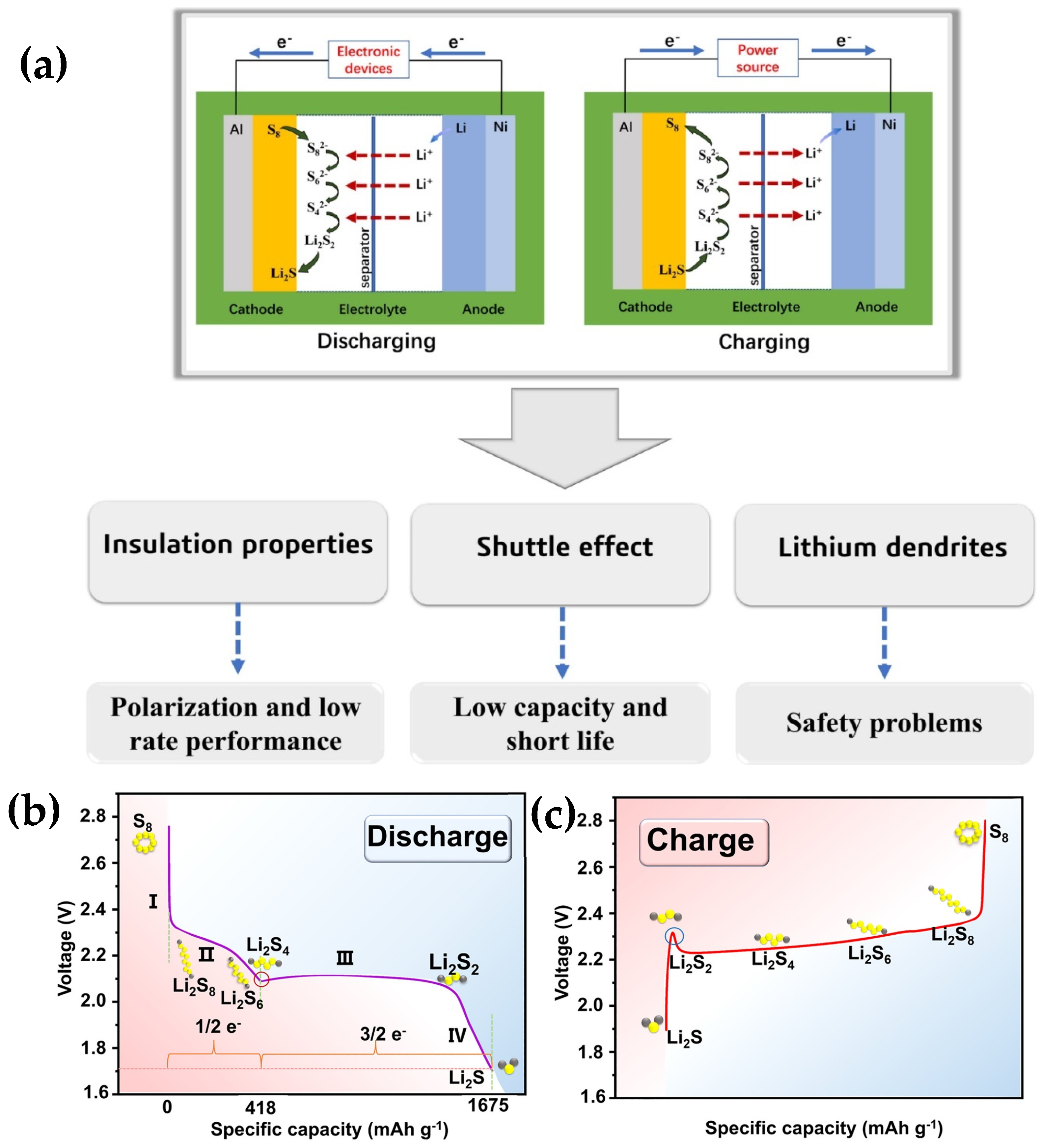
1.1.1. Reaction Mechanism of Lithium–Sulfur Batteries
- S8 to Li2S8: Solid cyclic S8 is first lithiated to form liquid Li2S8 and dissolved in the electrolyte, which is a ‘solid–liquid’ conversion process. This phenomenon aligns with the initial plateau observed in the discharge profile;
- Li2S8 to Li2S6: This stage represents a ‘liquid–liquid’ transformation, taking place at approximately 2.3 V (relative to Li+/Li), which is associated with the initial plateau in the discharge curve;
- Li+2S6 to Li2S4: This procedure is depicted by the second gradient. The initial three sulfur transformation steps contribute to approximately 25% of the theoretical discharge capacity, which is around 419 mAh g−1;
- Conversion of Li2S4 to Li2S2: The dissolved ions undergo precipitation to form a solid phase at approximately 2.05 V (relative to Li/Li), a process that manifests itself as a second discharge plateau;
- Conversion of Li+2S2 to Li2S: During the discharge process, the accumulation of Li2S2 on the electrode surface persists in undergoing reduction to form Li2S until the process concludes.
1.1.2. Development Potential of Lithium–Sulphur Batteries
1.2. Metal–Organic Frameworks: Promising Materials for Lithium–Sulfur Batteries Applications
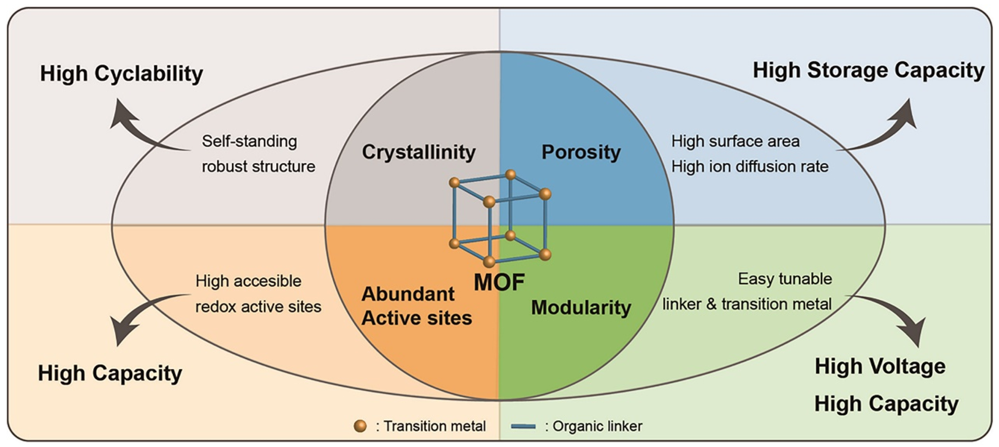
1.2.1. Overview of Metal–Organic Frameworks
1.2.2. Preparation of Metal–Organic Framework Materials
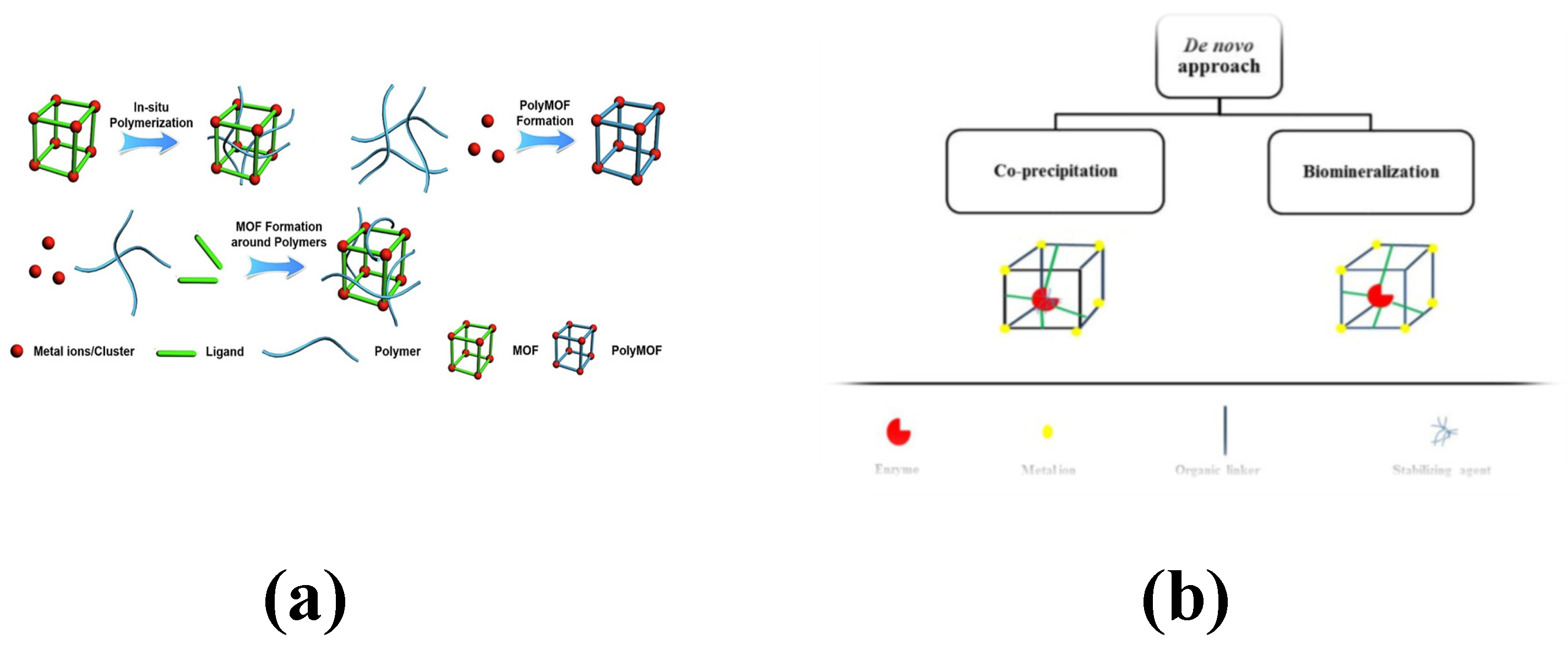
- MOF composites with polymers: Polymers are characterized by their flexibility, strength, and processability, in contrast with the crystalline and rigid nature of MOFs. By combining them, their respective advantages can be preserved. Several methods can be employed to achieve MOF–polymer composites. One approach involves blending MOFs with polymers to create a hybrid matrix film. Another method consists of covalently attaching polymers to the surface of the MOFs [39].
- MOF and enzyme composite: MOFs serve as carriers for enzyme immobilization, with incorporation methods broadly categorized into the co-precipitation embedding method and the biomineralization encapsulation method. In the co-precipitation method, auxiliary stabilizers are utilized to maintain the enzyme’s active form during the preparation process, ensuring encapsulation of the enzyme within the MOF structure. Alternatively, biomimetic mineralization, which does not require co-precipitants, involves directly mixing the enzyme with its corresponding MOF to form enzyme–MOF bio-complexes [40]. The key distinction lies in the location of the enzyme: in the former method, it is encapsulated inside the MOF, whereas in the latter, it is associated with the exterior of the MOF.
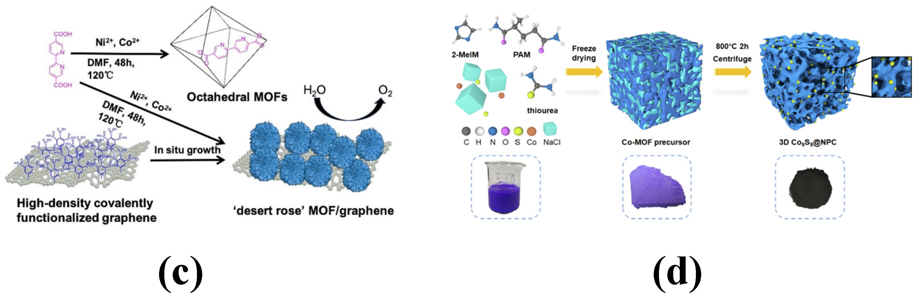
- MOF and graphene composites: The preparation of graphene/MOF composites typically involves three methods: in situ growth, interfacial growth, and co-molding. In the in situ growth method, the graphene matrix serves as a template to induce the growth of MOFs on its surface and within its internal pores. Alternatively, the interfacial growth and co-molding methods are employed to form composites by uniformly dispersing MOFs in a graphene solution, either through physical mixing or chemical binding [41].
- MOFs and metal nanoparticles (NPs): MOFs materials are used as the main materials, and the precursors of metal NPs are confined in the limited space of MOFs materials by the one-pot method, solution impregnation, vapor-phase deposition and solid-state milling, and then the size and morphology of the metal NPs are achieved by adding reductants or energizing the reducing gases, etc. These materials not only inherited the porous nature of MOFs but also combined with the high catalytic activity of metal nanoparticles, which makes the composites exhibit higher efficiency and selectivity in catalytic reactions [42].
2. Metal–Organic Frameworks for Cathode Applications in Lithium–Sulfur Batteries
2.1. Original Metal–Organic Frame
2.2. Metal–Organic Framework Composites
2.2.1. Composites with Graphene
2.2.2. Composites with Carbon Nanotubes (CNTs)
2.2.3. Composites with Conductive Polymers
2.2.4. Derivatives of Metal–Organic Frameworks
3. Alternative Strategies for Metal–Organic Frameworks to Improve the Performance of LSBs
3.1. Intermediate Layer Modified by Metal–Organic Framework Material
3.2. Separators Modified by Metal–Organic Framework Materials
3.3. Electrolytes Modified by Metal–Organic Framework Materials
4. Conclusions and Outlook
- When assessing the impact of MOFs on the performance of LSBs, a comprehensive analysis of the pore structure of MOFs is essential. While most studies have emphasized the role of pore size in mitigating the polysulfide shuttle effect, they often overlook the broader implications of pore size on the uniform distribution of sulfur and the sulfur loading capacity within MOFs. Notably, achieving uniform sulfur loading and increasing sulfur content remain significant challenges for many MOFs. Therefore, these factors must be comprehensively considered during the screening and design of MOFs with optimal pore sizes.
- Applying a uniform and comprehensive MOF coating onto the separator can significantly enhance the interfacial stability and cycling performance of the battery. This coating serves as an effective physical barrier to minimize the polysulfide shuttle effect, while simultaneously providing chemical adsorption sites to improve polysulfide immobilization. Current modification methods, such as vacuum filtration and in situ modification, fall short in meeting this requirement. Therefore, innovative techniques must be adopted for depositing MOF coatings. Promising approaches include chemical vapor deposition, magnetron sputtering, and atomic layer deposition.
- The development of novel redox-active MOFs presents a promising avenue, as these materials not only possess ultra-high specific surface areas and substantial porosity but also offer customizable host–guest interaction platforms. Among these, MOFs based on tetravalent metals and carboxylic acid ligands have garnered particular attention due to their exceptional chemical stability.
- The industrial-scale production of metal–organic framework (MOF) materials holds the potential to vastly expand their applicability in commercial lithium–sulfur batteries (LSBs). To achieve cost reduction, it is crucial to select earth-abundant raw materials and employ synthesis methods that yield high productivity with minimal by-products. Emerging synthesis strategies, such as solid–solid and gas-phase methods, which feature shorter production cycles and higher yields, will play a key role in advancing the industrial manufacturing of MOF materials.
Author Contributions
Funding
Acknowledgments
Conflicts of Interest
References
- Guo, J.; Meng, X.; Wang, Q.; Zhang, Y.; Yan, S.; Luo, S. Advancements in Lithium–Oxygen Batteries: A Comprehensive Review of Cathode and Anode Materials. Batteries 2024, 10, 260. [Google Scholar] [CrossRef]
- Hou, S.E.; Alonso, J.A.; Rajasekhara, S.; Martínez-Lope, M.J.; Fernández-Díaz, M.T.; Goodenough, J.B. Defective Ni Perovskites as Cathode Materials in Intermediate-Temperature Solid-Oxide Fuel Cells: A Structure-Properties Correlation. Chem. Mater. 2010, 22, 1071–1079. [Google Scholar] [CrossRef]
- Ting, M.; Yue, H.X.; Xiao, Y.B.; Huang, Y.X.; Li, X.; Gao, X.; He, N.; Zhan, C.Z.; Ding, N. A review of organic sulfur applications in lithium-sulfur batteries. J. Power Sources 2024, 625, 717. [Google Scholar]
- Lv, Z.-C.; Wang, P.-F.; Wang, J.-C.; Tian, S.-H.; Yi, T.-F. Key challenges, recent advances and future perspectives of rechargeable lithium-sulfur batteries. J. Ind. Eng. Chem 2023, 124, 68–88. [Google Scholar] [CrossRef]
- Miao, Y.; Zheng, Y.; Tao, F.; Chen, Z.; Xiong, Y.; Ren, F.; Liu, Y. Synthesis and application of single-atom catalysts in sulfur cathode for high-performance lithium–sulfur batteries. Chin. Chem. Lett. 2023, 34, 107121. [Google Scholar] [CrossRef]
- Chavan, V.D.; Patil, P.D.; Patil, C.S.; Patil, S.R.; Katkar, P.K.; Sheikh, Z.A.; Ustad, R.E.; Kim, H.; Kadam, K.D.; Patil, H.S.; et al. Advanced functional materials and their coordinated composites for next-generation Li-S batteries: A brief review. J. Energy Storage 2024, 88, 111572. [Google Scholar] [CrossRef]
- Liu, J.; Wang, F.; Wei, H.; Liu, Y.; Zhai, X.; Wen, S.; Zhang, Q. Fabrication and application of binder-free cathodes in high-performance lithium-chalcogen (S, Se, Te) batteries: A review. Chin. Chem. Lett. 2024, 110475. [Google Scholar] [CrossRef]
- Li, Z.; He, Q.; Xu, X.; Zhao, Y.; Liu, X.; Zhou, C.; Ai, D.; Xia, L.; Mai, L. A 3D Nitrogen-Doped Graphene/TiN Nanowires Composite as a Strong Polysulfide Anchor for Lithium–Sulfur Batteries with Enhanced Rate Performance and High Areal Capacity. Adv. Mater. 2018, 30, 1804089. [Google Scholar] [CrossRef] [PubMed]
- Mei, J.; Liao, T.; Liang, J.; Qiao, Y.; Dou, S.X.; Sun, Z. Toward Promising Cathode Catalysts for Nonlithium Metal–Oxygen Batteries. Adv. Energy Mater. 2019, 10, 1901997. [Google Scholar] [CrossRef]
- Phung, J.; Zhang, X.; Deng, W.; Li, G. An overview of MOF-based separators for lithium-sulfur batteries. Sustain. Mater. Technol. 2022, 31, e00374. [Google Scholar] [CrossRef]
- Yuan, N.; Sun, W.; Yang, J.; Gong, X.; Liu, R. Multifunctional MOF-Based Separator Materials for Advanced Lithium–Sulfur Batteries. Adv. Mater. 2021, 8, 2001941. [Google Scholar] [CrossRef]
- Ajdari, F.B.; Shahrak, M.N.; Ershadi, M.; Shakourian-Fard, M.; Abbasi, F.; Kamath, G.; Beni, F.A.; Ghasemi, F.; Ghenaatian, H.R.; Ramakrishna, S. Lithium–sulfur batteries beyond lithium-ion counterparts: Reasonable substituting challenges, current research focus, binding critical role, and cathode designing. Rev. Chem. Eng. 2024, 40, 973–1022. [Google Scholar] [CrossRef]
- Zhou, X.; Wang, Y.; Gu, Y.; Su, J.; Liu, Y.; Yin, Y.; Yuan, S.; Ma, J.; Jin, Z.; Zuo, J.-L. All-purpose redox-active metal-organic frameworks as both cathodic and anodic host materials for advanced lithium-sulfur batteries. Matter 2024, 7, 3069–3082. [Google Scholar] [CrossRef]
- Zhang, J.; Jiang, G.; Cumberland, T.; Xu, P.; Wu, Y.; Delaat, S.; Yu, A.; Chen, Z. A highly sensitive breathable fuel cell gas sensor with nanocomposite solid electrolyte. InfoMat 2019, 1, 234–241. [Google Scholar] [CrossRef]
- Wang, Y.; Li, B.; Zhang, B.; Tian, S.; Yang, X.; Ye, H.; Xia, Z.; Zheng, G. Application of MOFs-derived mixed metal oxides in energy storage. J. Electroanal. Chem. 2020, 878, 114576. [Google Scholar] [CrossRef]
- Ran, F.; Xu, X.; Pan, D.; Liu, Y.; Bai, Y.; Shao, L. Ultrathin 2D Metal–Organic Framework Nanosheets In situ Interpenetrated by Functional CNTs for Hybrid Energy Storage Device. Nano-Micro Lett. 2020, 12, 46. [Google Scholar] [CrossRef]
- Zhang, K.; Zhang, Y.; Zhang, Q.; Liang, Z.; Gu, L.; Guo, W.; Zhu, B.; Guo, S.; Zou, R. Metal-organic framework-derived Fe/Cu-substituted Co nanoparticles embedded in CNTs-grafted carbon polyhedron for Zn-air batteries. Carbon Energy 2020, 2, 283–293. [Google Scholar] [CrossRef]
- Xia, J.; Xu, P.; Wang, W.; Hu, P.; Sun, Y.; Shao, J. Carbon Nanofiber-Based Sandwich Free-Standing Cathode for High-Performance Lithium–Sulfur Batteries. Langmuir 2024, 40, 15688–15699. [Google Scholar] [CrossRef]
- Theibault, M.J.; McCormick, C.R.; Lang, S.; Schaak, R.E.; Abruña, H.D. High Entropy Sulfide Nanoparticles as Lithium Polysulfide Redox Catalysts. ACS Nano 2023, 17, 18402–18410. [Google Scholar] [CrossRef]
- Zhang, J.; Ma, W.; Feng, Z.; Wu, F.; Wei, D.; Xi, B.; Xiong, S. P-doped BN nanosheets decorated graphene as the functional interlayer for Li–S batteries. J. Energy Chem. 2019, 39, 54–60. [Google Scholar] [CrossRef]
- Zhu, X.; Wang, L.; Bai, Z.; Lu, J.; Wu, T. Sulfide-Based All-Solid-State Lithium–Sulfur Batteries: Challenges and Perspectives. Nano-Micro Lett. 2023, 15, 75. [Google Scholar] [CrossRef] [PubMed]
- Lim, W.G.; Kim, S.; Jo, C.; Lee, J. A Comprehensive Review of Materials with Catalytic Effects in Li-S Batteries: Enhanced Redox Kinetics. Angew. Chem. Int. Ed. 2019, 58, 18746–18757. [Google Scholar] [CrossRef]
- Zak, J.J.; Kim, S.S.; Laskowski, F.A.L.; See, K.A. An Exploration of Sulfur Redox in Lithium Battery Cathodes. J. Am. Chem. Soc. 2022, 144, 10119–10132. [Google Scholar] [CrossRef]
- Zhang, M.; Chen, W.; Xue, L.; Jiao, Y.; Lei, T.; Chu, J.; Huang, J.; Gong, C.; Yan, C.; Yan, Y.; et al. Adsorption-Catalysis Design in the Lithium-Sulfur Battery. Adv. Energy Mater. 2020, 10, 1903008. [Google Scholar] [CrossRef]
- Zhou, G.M.; Chen, H.; Cui, Y. Formulating energy density for designing practical lithium–sulfur batteries. Nat. Energy 2022, 7, 312–319. [Google Scholar] [CrossRef]
- Qi, F.; Sun, Z.; Fan, X.; Wang, Z.; Shi, Y.; Hu, G.; Li, F. Tunable Interaction between Metal-Organic Frameworks and Electroactive Components in Lithium–Sulfur Batteries: Status and Perspectives. Adv. Energy Mater. 2021, 11, 2100387. [Google Scholar] [CrossRef]
- Zhang, Y.; Zhang, X.; Silva, S.R.P.; Ding, B.; Zhang, P.; Shao, G. Lithium–Sulfur Batteries Meet Electrospinning: Recent Advances and the Key Parameters for High Gravimetric and Volume Energy Density. Adv. Sci. 2021, 9, 2103879. [Google Scholar] [CrossRef]
- Zhao, F.L.; Xue, J.H.; Shao, W.; Yu, H.; Huang, W.; Xiao, J. Toward high-sulfur-content, high-performance lithium-sulfur batteries: Review of materials and technologies. J. Energy Chem. 2023, 80, 625–657. [Google Scholar] [CrossRef]
- Lu, J.; Luo, S.; Qi, Z.; Chen, T.; Li, X.; Yuan, T.; Pang, Y.; Zheng, S. Recent advances in transition metal chalcogenide derivatives from metal-organic frameworks for lithium-sulfur batteries. Cell Rep. Phys. Sci. 2024, 5, 102028. [Google Scholar] [CrossRef]
- Chen, Z.X.; Zhao, M.; Hou, L.P.; Zhang, X.Q.; Li, B.Q.; Huang, J.Q. Toward Practical High-Energy-Density Lithium-Sulfur Pouch Cells: A Review. Adv. Mater. 2022, 34, 2201555. [Google Scholar] [CrossRef] [PubMed]
- Feng, S.; Fu, Z.H.; Chen, X.; Zhang, Q. A review on theoretical models for lithium-sulfur battery cathodes. InfoMat 2022, 4, e12304. [Google Scholar] [CrossRef]
- Hussain, I.; Zhang, K. MOF-derived scaffolds as electrode materials: A mini-review. Nanoscale 2024, 16, 15515–15528. [Google Scholar] [CrossRef] [PubMed]
- Hwang, J. A review of synthesis strategies for MOF-derived single atom catalysts. Korean J. Chem. Eng. 2021, 38, 1104–1116. [Google Scholar] [CrossRef]
- Li, X.; Yang, X.; Xue, H.; Pang, H.; Xu, Q. Metal–organic frameworks as a platform for clean energy applications. EnergyChem 2020, 2, 100027. [Google Scholar] [CrossRef]
- Lu, C.; Clayville, B.; Choi, J.Y.; Park, J. 2D metal-organic frameworks as an emerging platform with tunable electronic structures. Chem 2023, 9, 2757–2770. [Google Scholar] [CrossRef]
- Xuan, W.; Zhu, C.; Liu, Y.; Cui, Y. Mesoporous metal–organic framework materials. Chem. Soc. Rev. 2011, 41, 1677–1695. [Google Scholar] [CrossRef] [PubMed]
- Islamoglu, T.; Goswami, S.; Li, Z.; Howarth, A.J.; Farha, O.K.; Hupp, J.T. Correction to Postsynthetic Tuning of Metal–Organic Frameworks for Targeted Applications. Acc. Chem. Res. 2018, 51, 212. [Google Scholar] [CrossRef] [PubMed]
- Lee, J.; Choi, I.; Kim, E.; Park, J.; Nam, K.W. Metal-organic frameworks for high-performance cathodes in batteries. iScience 2024, 27, 110211. [Google Scholar] [CrossRef]
- Yang, S.; Karve, V.V.; Justin, A.; Kochetygov, I.; Espín, J.; Asgari, M.; Trukhina, O.; Sun, D.T.; Peng, L.; Queen, W.L. Enhancing MOF performance through the introduction of polymer guests. Coord. Chem. Rev. 2021, 427, 213525. [Google Scholar] [CrossRef]
- Nadar, S.S.; Vaidya, L.; Rathod, V.K. Enzyme embedded metal organic framework (enzyme–MOF): De novo approaches for immobilization. Int. J. Biol. Macromol. 2020, 149, 861–876. [Google Scholar] [CrossRef]
- Li, Z.; Guo, Y.; Li, K.; Wang, S.; De Bonis, E.; Cao, H.; Mertens, S.F.L.; Teng, C. Shape control of bimetallic MOF/Graphene composites for efficient oxygen evolution reaction. J. Electroanal. Chem. 2023, 930, 117144. [Google Scholar] [CrossRef]
- Ma, Y.; Wu, M.; Li, L.; Li, Z.; Zhao, X.; Lian, R.; Zhang, W. MOF derived Co9S8 nanoparticles embedded in 3D N-doped carbon matrix for high-performance K-ion battery anode. Appl. Surf. Sci. 2022, 600, 154159. [Google Scholar] [CrossRef]
- Demir-Cakan, R.; Morcrette, M.; Nouar, F.; Davoisne, C.; Devic, T.; Gonbeau, D.; Dominko, R.; Serre, C.; Férey, G.; Tarascon, J.-M. Cathode Composites for Li–S Batteries via the Use of Oxygenated Porous Architectures. J. Am. Chem. Soc. 2011, 133, 16154–16160. [Google Scholar] [CrossRef] [PubMed]
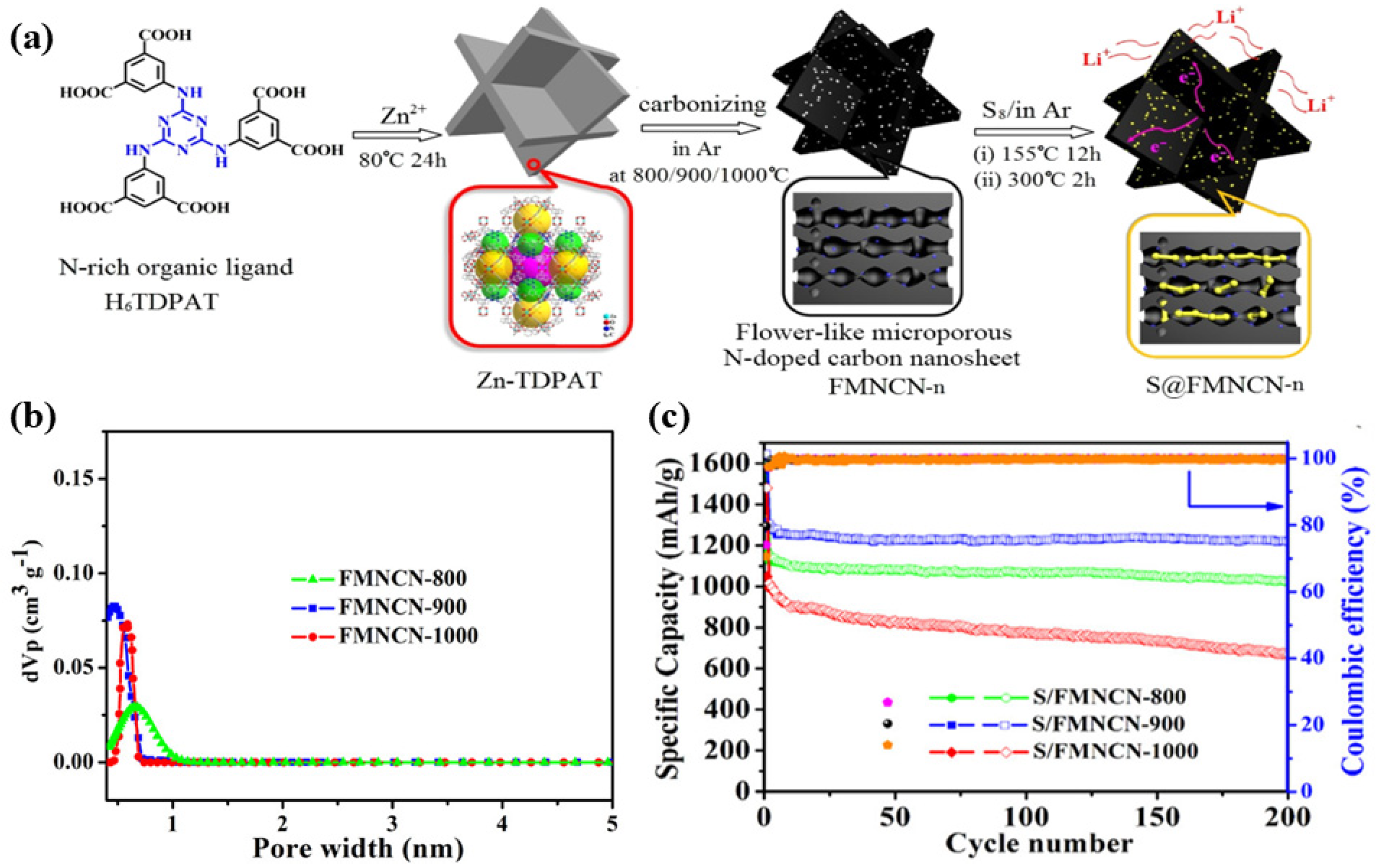
- Hong, X.-J.; Tang, X.-Y.; Wei, Q.; Song, C.-L.; Wang, S.-Y.; Dong, R.-F.; Cai, Y.-P.; Si, L.-P. Efficient Encapsulation of Small S2-4 Molecules in MOF-Derived Flowerlike Nitrogen-Doped Microporous Carbon Nanosheets for High-Performance Li–S Batteries. ACS Appl. Mater. Interfaces 2018, 10, 9435–9443. [Google Scholar] [CrossRef] [PubMed]
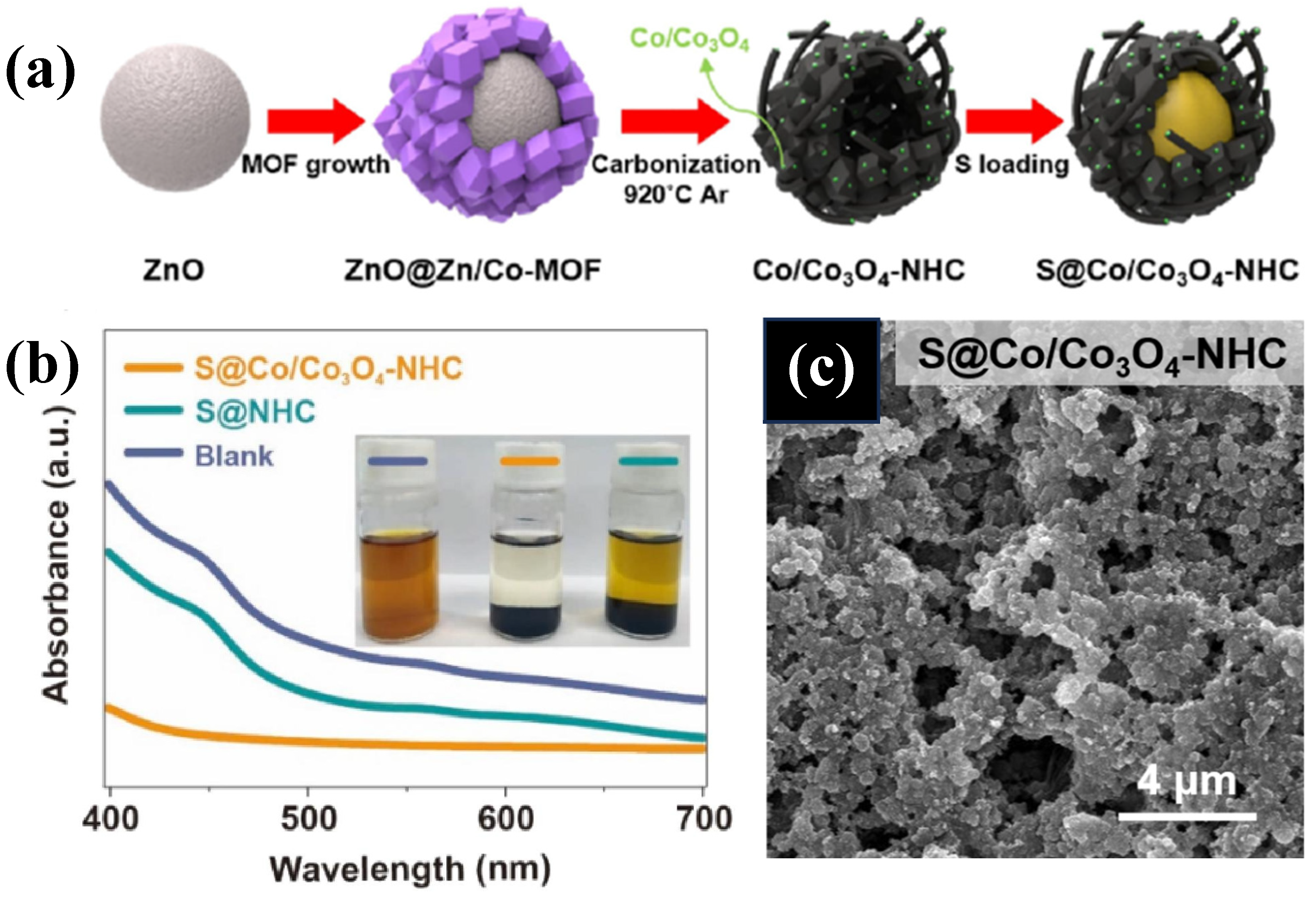
- Jeon, Y.; Lee, J.; Jo, H.; Hong, H.; Lee, L.Y.S.; Piao, Y. Co/Co3O4-embedded N-doped hollow carbon composite derived from a bimetallic MOF/ZnO Core-shell template as a sulfur host for Li-S batteries. Chem. Eng. J. 2021, 407, 126967. [Google Scholar] [CrossRef]
- Park, M.-S.; Yu, J.-S.; Kim, K.J.; Jeong, G.; Kim, J.-H.; Jo, Y.-N.; Hwang, U.; Kang, S.; Woo, T.; Kim, Y.-J. One-step synthesis of a sulfur-impregnated graphene cathode for lithium–sulfur batteries†. Phys. Chem. Chem. Phys. 2012, 14, 6796–6804. [Google Scholar] [CrossRef] [PubMed]
- Zhang, M.; Shan, Y.; Kong, Q.; Pang, H. Applications of metal–organic framework–graphene composite materials in electrochemical energy storage. FlatChem 2022, 32, 100332. [Google Scholar] [CrossRef]
- Baumann, A.E.; Downing, J.R.; Burns, D.A.; Hersam, M.C.; Thoi, V.S. Graphene–Metal–Organic Framework Composite Sulfur Electrodes for Li–S Batteries with High Volumetric Capacity. ACS Appl. Mater. Interfaces 2020, 12, 37173–37181. [Google Scholar] [CrossRef] [PubMed]
- Jiao, X.; Deng, T.; Men, X.; Zuo, Y.; Wang, J. Indium metal-organic framework with catalytic sites coated conductive graphene for high-performance lithium-sulfur batteries. Ceram. Int. 2022, 48, 16754–16763. [Google Scholar] [CrossRef]
- Qian, X.; Cheng, J.; Wang, Y.; Jin, L.; Chen, J.; Hao, Q.; Zhang, K. A Ni-MOF derived graphene oxide combined Ni3S2–Ni/C composite and its use in the separator coating for lithium sulfur batteries. Phys. Chem. Chem. Phys. 2023, 25, 5559–5568. [Google Scholar] [CrossRef] [PubMed]
- Zuluaga-Gómez, C.C.; Plaza-Rivera, C.O.; Tripathi, B.; Katiyar, R.K.; Pradhan, D.K.; Morell, G.; Lin, Y.; Correa, M.; Katiyar, R.S. Holey Graphene/Ferroelectric/Sulfur Composite Cathodes for High-Capacity Lithium–Sulfur Batteries. ACS Omega 2023, 8, 13097–13108. [Google Scholar] [CrossRef]
- Xu, G.; Zuo, Y.; Huang, B. Metal-organic framework-74-Ni/carbon nanotube composite as sulfur host for high performance lithium-sulfur batteries. J. Electroanal. Chem. 2018, 830, 43–49. [Google Scholar] [CrossRef]
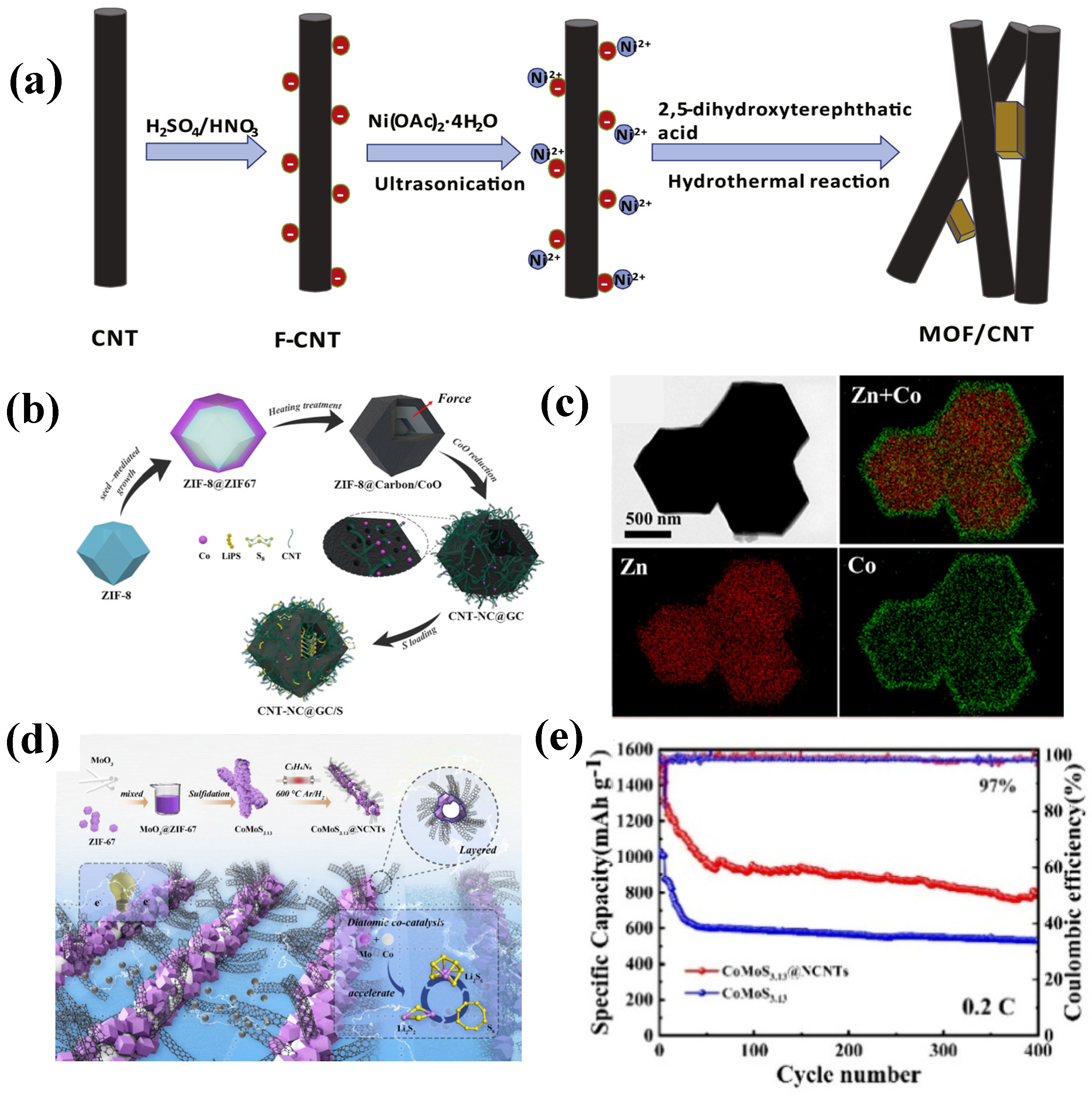
- Zhou, F.; Qiao, Z.; Zhang, Y.; Xu, W.; Zheng, H.; Xie, Q.; Luo, Q.; Wang, L.; Qu, B.; Peng, D.-L. Bimetallic MOF-derived CNTs-grafted carbon nanocages as sulfur host for high-performance lithium–sulfur batteries. Electrochim. Acta 2020, 349, 136378. [Google Scholar] [CrossRef]
- Li, Z.; Wu, H.B.; Lou, X.W. Rational designs and engineering of hollow micro-/nanostructures as sulfur hosts for advanced lithium–sulfur batteries. Energy Environ. Sci. 2016, 9, 3061–3070. [Google Scholar] [CrossRef]
- Wang, J.; Chen, X.; Chen, L.; Jiang, A.; Zeng, Y.; Li, X.; Xiao, J. Layered CoMoS3.13@NCNTs with a Rod-Shaped Skeleton as the Cathode of Lithium–Sulfur Batteries. ACS Sustain. Chem. Eng. 2024, 12, 9864–9873. [Google Scholar] [CrossRef]
- Niščáková, V.; Gubóová, A.; Petruš, O.; Fei, H.; Almáši, M.; Fedorková, A.S. Investigation of polypyrrole based composite material for lithium sulfur batteries. Sci. Rep. 2024, 14, 22928. [Google Scholar] [CrossRef]
- Yang, J.; Li, S.; Wu, G.; Bao, J.; Xu, S.; Gu, C.; Lv, J.; Huang, J.; Joo, S.W. Preparation of polyaniline-coated cobalt nitride nanoflowers as sulfur host for advanced lithium–sulfur battery. J. Alloys Compd. 2024, 981, 173701. [Google Scholar] [CrossRef]
- Wei, W.; Li, J.; Wang, Q.; Liu, D.; Niu, J.; Liu, P. Hierarchically Porous SnO2 Nanoparticle-Anchored Polypyrrole Nanotubes as a High-Efficient Sulfur/Polysulfide Trap for High-Performance Lithium–Sulfur Batteries. ACS Appl. Mater. Interfaces 2020, 12, 6362–6370. [Google Scholar] [CrossRef] [PubMed]
- Liu, P.-Y.; Zhao, J.-J.; Dong, Z.-P.; Liu, Z.-L.; Wang, Y.-Q. Interwoving polyaniline and a metal-organic framework grown in situ for enhanced supercapacitor behavior. J. Alloys Compd. 2021, 854, 157181. [Google Scholar] [CrossRef]
- Zhang, H.; Feng, S.; Li, X.; Chen, X.; Chen, L.; Xiao, J. Porous structure of fixed sulfur and networked electronic channels in three-dimensional skeletal structure of polyaniline and MOF-derived materials. Colloids Surf. A Physicochem. Eng. Asp. 2023, 669, 131440. [Google Scholar] [CrossRef]
- Li, B.; Xie, M.; Yi, G.; Zhang, C. Biomass-derived activated carbon/sulfur composites as cathode electrodes for Li–S batteries by reducing the oxygen content. RSC Adv. 2020, 10, 2823–2829. [Google Scholar] [CrossRef] [PubMed]
- Sun, Z.; Sun, B.; Xue, J.; He, J.; Zhao, R.; Chen, Z.; Sun, Z.; Liu, H.; Dou, S. ZIF-67/ZIF-8 and its Derivatives for Lithium Sulfur Batteries. Adv. Funct. Mater. 2024, 35, 2414671. [Google Scholar] [CrossRef]
- Liu, Y.; Dong, S.; Wang, L.; Chen, G.; Hou, Y.; Cao, Z.; Zhang, Y. Bimetal cobalt-zinc MOF and its derivatives as anode materials for lithium-ion batteries. J. Solid State Electrochem. 2022, 26, 2301–2313. [Google Scholar] [CrossRef]
- Kyom Kim, D.; Seul Byun, J.; Moon, S.; Choi, J.; Ha Chang, J.; Suk, J. Molten salts approach of metal-organic framework-derived nitrogen-doped porous carbon as sulfur host for lithium-sulfur batteries. Chem. Eng. J. 2022, 441, 135945. [Google Scholar] [CrossRef]
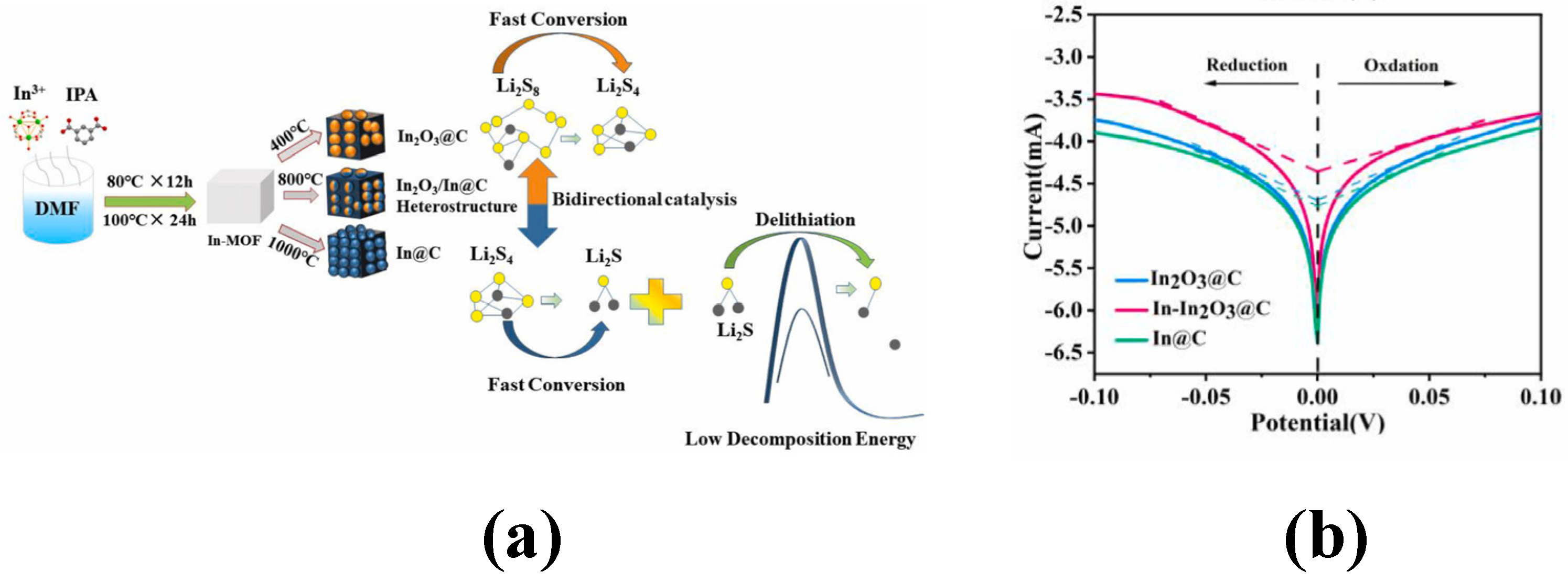
- Bai, Y.; Jiao, X.; Chen, L.; Huang, L.; Xue, K.; Wu, D.; Li, X.; Li, Y.; Deng, T.; Wang, J. Regulating In-MOF derivatives for bidirectionally boosting redox kinetics of sulfur cathodes. Ceram. Int. 2024, 50, 8370–8377. [Google Scholar] [CrossRef]
- Dong, C.; Zhou, C.; Wu, M.; Yu, Y.; Yu, K.; Yan, K.; Shen, C.; Gu, J.; Yan, M.; Sun, C.; et al. Boosting Bi-Directional Redox of Sulfur with Dual Metal Single Atom Pairs in Carbon Spheres Toward High-Rate and Long-Cycling Lithium–Sulfur Battery. Adv. Energy Mater. 2023, 13, 2301505. [Google Scholar] [CrossRef]
- Wang, Z.; Liu, C.; Wang, Y.; Zhang, S.; Huang, M.; Bai, J.; Wang, H.; Liu, X. Nitrogen-doped carbon nanofiber loaded MOF-derived NiCo bimetallic nanoparticles accelerate the redox transformation of polysulfide for lithium- sulfur batteries. J. Electroanal. Chem. 2024, 959, 118185. [Google Scholar] [CrossRef]
- Guan, J.; Feng, X.; Zeng, Q.; Li, Z.; Liu, Y.; Chen, A.; Wang, H.; Cui, W.; Liu, W.; Zhang, L. A New In Situ Prepared MOF-Natural Polymer Composite Electrolyte for Solid Lithium Metal Batteries with Superior High- Rate Capability and Long-Term Cycling Stability at Ultrahigh Current Density. Adv. Sci. 2022, 10, 2203916. [Google Scholar] [CrossRef] [PubMed]
- Luo, S.; Deng, N.; Wang, H.; Zeng, Q.; Li, Y.; Kang, W.; Cheng, B. Facilitating Li+ conduction channels and suppressing lithium dendrites by introducing Zn-based MOFs in composite electrolyte membrane with excellent thermal stability for solid-state lithium metal batteries. Chem. Eng. J. 2023, 474, 145683. [Google Scholar] [CrossRef]
- Wang, Q.; Cui, K.-P.; Liu, T.; Li, C.-X.; Liu, J.; Kong, D.-C.; Weerasooriya, R.; Chen, X. In situ growth of NH2-MIL-101 metal organic frameworks on biochar for glyphosate adsorption. Chemosphere 2023, 331, 138827. [Google Scholar] [CrossRef]
- Raza, H.; Cheng, J.; Lin, C.; Majumder, S.; Zheng, G.; Chen, G. High-entropy stabilized oxides derived via a low-temperature template route for high-performance lithium-sulfur batteries. EcoMat 2023, 5, e12324. [Google Scholar] [CrossRef]
- Raza, H.; Cheng, J.; Wang, J.; Kandasamy, S.; Zheng, G.; Chen, G. Titanium-containing high entropy oxide (Ti-HEO): A redox expediting electrocatalyst towards lithium polysulfides for high performance Li-S batteries. Nano Res. Energy 2024, 3, e9120116. [Google Scholar] [CrossRef]
- Zhou, C.; Li, Z.; Xu, X.; Mai, L. Metal-organic frameworks enable broad strategies for lithium-sulfur batteries. Natl. Sci. Rev. 2021, 8, nwab055. [Google Scholar] [CrossRef] [PubMed]
- Zhou, L.; Danilov, D.L.; Eichel, R.A.; Notten, P.H.L. Host Materials Anchoring Polysulfides in Li–S Batteries Reviewed. Adv. Energy Mater. 2020, 11, 2001304. [Google Scholar] [CrossRef]
- Chen, Y.; Wang, T.; Tian, H.; Su, D.; Zhang, Q.; Wang, G. Advances in Lithium–Sulfur Batteries: From Academic Research to Commercial Viability. Adv. Mater. 2021, 33, 2003666. [Google Scholar] [CrossRef] [PubMed]
- Zhang, T.; Zhang, L.; Hou, Y. MXenes: Synthesis strategies and lithium-sulfur battery applications. eScience 2022, 2, 164–182. [Google Scholar] [CrossRef]
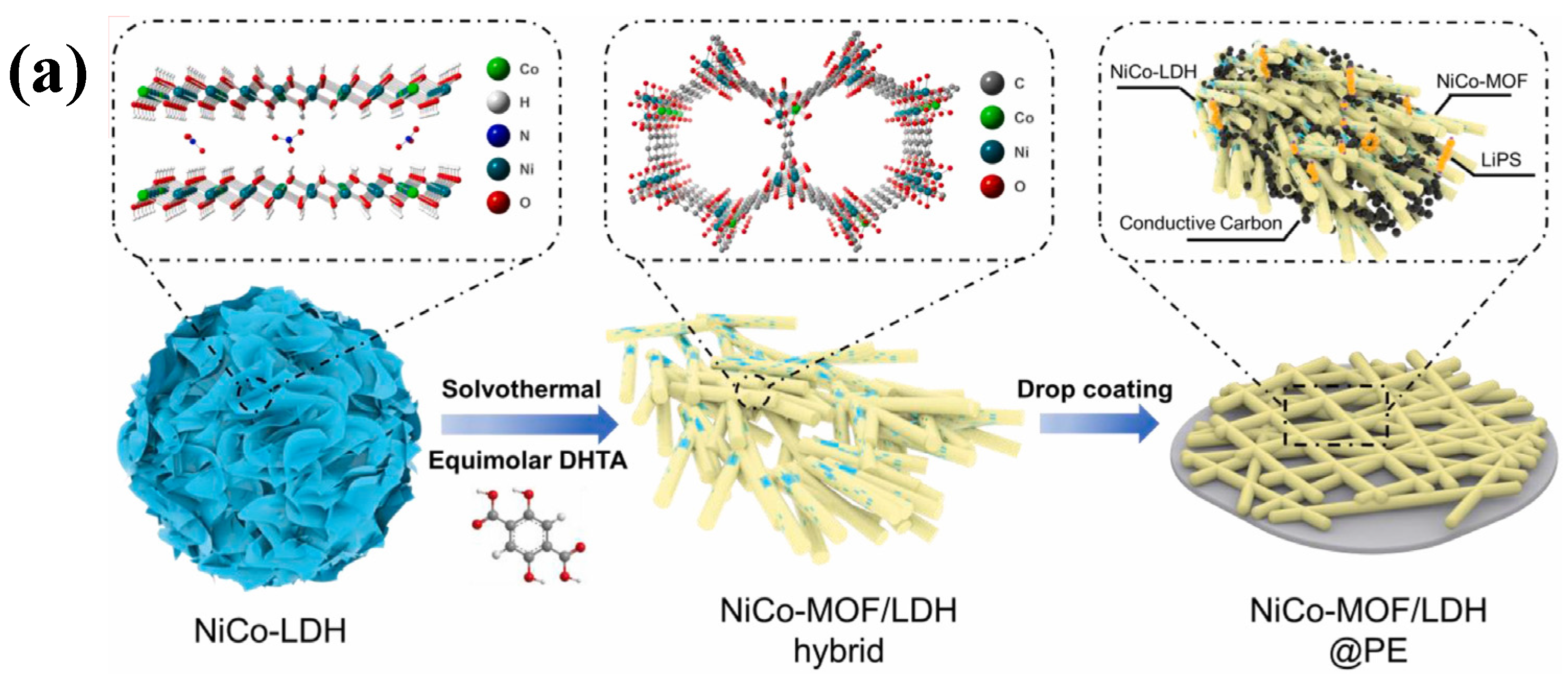
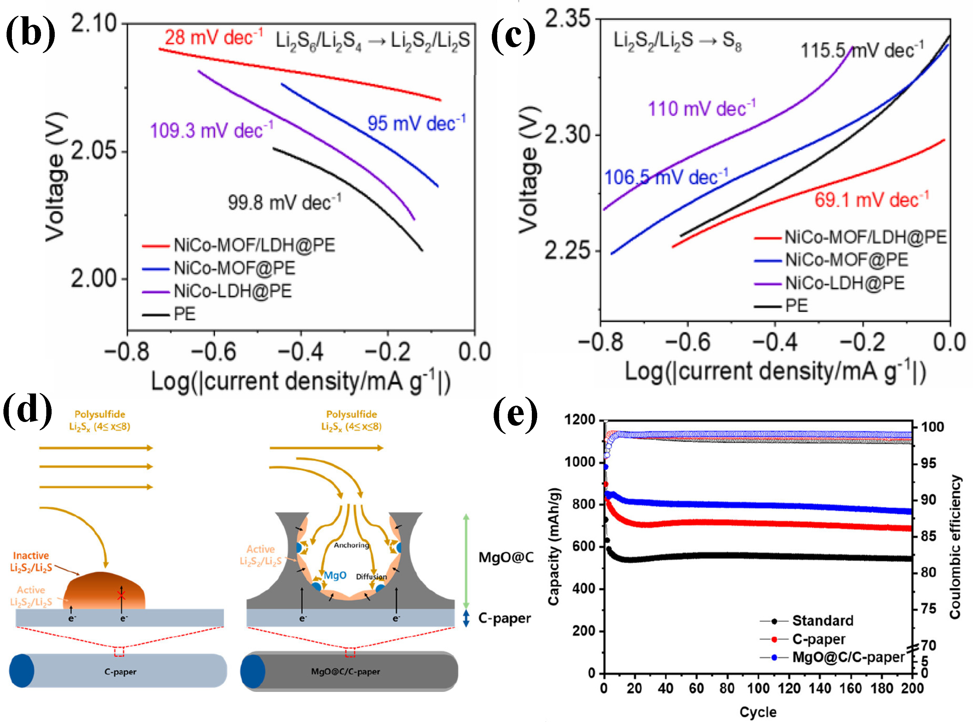
- Yang, Y.; Ma, S.; Xia, M.; Guo, Y.; Zhang, Y.; Liu, L.; Zhou, C.; Chen, G.; Wang, X.; Wu, Q.; et al. Elaborately converting hierarchical NiCo–LDH to rod–like LDH–decorated MOF as interlayer for high–performance lithium–sulfur battery. Mater. Today Phys. 2023, 35, 101112. [Google Scholar] [CrossRef]
- Kang, H.; Shin, J.; Kim, T.-H.; Lee, Y.; Lee, D.; Lee, J.; Kim, G.; Cho, E. Metal–Organic Framework-Derived Magnesium Oxide@Carbon Interlayer for Stable Lithium–Sulfur Batteries. ACS Sustain. Chem. Eng. 2023, 11, 1344–1354. [Google Scholar] [CrossRef]
- Razaq, R.; Din, M.M.U.; Småbråten, D.R.; Eyupoglu, V.; Janakiram, S.; Sunde, T.O.; Allahgoli, N.; Rettenwander, D.; Deng, L. Synergistic Effect of Bimetallic MOF Modified Separator for Long Cycle Life Lithium-Sulfur Batteries. Adv. Energy Mater. 2023, 14, 2302897. [Google Scholar] [CrossRef]
- Zhou, C.; Dong, C.; Wang, W.; Tian, Y.; Shen, C.; Yan, K.; Mai, L.; Xu, X. An ultrathin and crack-free metal-organic framework film for effective polysulfide inhibition in lithium–sulfur batteries. Interdiscip. Mater. 2024, 3, 306–315. [Google Scholar] [CrossRef]
- Li, C.; Liu, R.; Xiao, Y.; Cao, F.; Zhang, H. Recent progress of separators in lithium-sulfur batteries. Energy Storage Mater. 2021, 40, 439–460. [Google Scholar] [CrossRef]
- Luo, Z.; Wu, Y.; Xu, X.; Ju, W.; Lei, W.; Wu, D.; Pan, J.; Ouyang, X. Surface-coated AlF3 nanolayers enable polysulfide confinement within biomass-derived nitrogen-doped hierarchical porous carbon microspheres for improved lithium-sulfur batteries. J. Colloid Interface Sci. 2024, 660, 657–668. [Google Scholar] [CrossRef] [PubMed]
- Wang, T.; He, J.; Zhu, Z.; Cheng, X.-B.; Zhu, J.; Lu, B.; Wu, Y. Heterostructures Regulating Lithium Polysulfides for Advanced Lithium-Sulfur Batteries. Adv. Mater. 2023, 35, 2303520. [Google Scholar] [CrossRef] [PubMed]
- Wang, Y.; Ai, R.; Wang, F.; Hu, X.; Zeng, Y.; Hou, J.; Zhao, J.; Zhang, Y.; Zhang, Y.; Li, X. Research Progress on Multifunctional Modified Separator for Lithium–Sulfur Batteries. Polymers 2023, 15, 993. [Google Scholar] [CrossRef]
- Zhou, J.; Sun, A. Progress in the advancement of atomically dispersed catalysts for enhanced performance lithium-sulfur batteries. Chem. Eng. J. 2024, 488, 150719. [Google Scholar] [CrossRef]
- Zhu, Y.; Chen, Z.; Chen, H.; Fu, X.; Awuye, D.E.; Yin, X.; Zhao, Y. Breaking the Barrier: Strategies for Mitigating Shuttle Effect in Lithium–Sulfur Batteries Using Advanced Separators. Polymers 2023, 15, 3955. [Google Scholar] [CrossRef] [PubMed]
- Zhao, S.; Hao, Q.; Qian, X.; Jin, L.; Li, B.; Xu, H. Application of Y-Zn-MOF derived Y2O3/ZnO@C in modification of lithium-sulfur battery separator. J. Energy Storage 2024, 101, 113833. [Google Scholar] [CrossRef]
- Liang, Z.; Lin, D.; Zhao, J.; Lu, Z.; Liu, Y.; Liu, C.; Lu, Y.; Wang, H.; Yan, K.; Tao, X.; et al. Composite lithium metal anode by melt infusion of lithium into a 3D conducting scaffold with lithiophilic coating. Proc. Natl. Acad. Sci. USA 2016, 113, 2862–2867. [Google Scholar] [CrossRef] [PubMed]
- Zhang, R.; Chen, X.-R.; Chen, X.; Cheng, X.-B.; Zhang, X.-Q.; Yan, C.; Zhang, Q. Lithiophilic Sites in Doped Graphene Guide Uniform Lithium Nucleation for Dendrite-Free Lithium Metal Anodes. Angew. Chem. Int. Ed. 2017, 56, 7764–7768. [Google Scholar] [CrossRef] [PubMed]
- Han, D.-D.; Wang, Z.-Y.; Pan, G.-L.; Gao, X.-P. Metal–Organic-Framework-Based Gel Polymer Electrolyte with Immobilized Anions To Stabilize a Lithium Anode for a Quasi-Solid-State Lithium–Sulfur Battery. ACS Appl. Mater. Interfaces 2019, 11, 18427–18435. [Google Scholar] [CrossRef] [PubMed]
- Li, J.; Xie, F.; Pang, W.; Liang, Q.; Yang, X.; Zhang, L. Regulate transportation of ions and polysulfides in all–solid-state Li-S batteries using ordered-MOF composite solid electrolyte. Sci. Adv. 2024, 10, eadl3925. [Google Scholar] [CrossRef]


| Composites | Initial Discharge Capacity (mAh g−1) (Current Density) | Terminal Discharge Capacity (mAh g−1) (Cycle Number) | Capacity Retention Rate | Loading Amount of Sulfur | Reference |
|---|---|---|---|---|---|
| S@FMNCN-800 | 1645 (0.1 C) | 1220 (200) | 74.16% | 26.0% | [44] |
| S@FMNCN-900 | 1588 (0.1 C) | 1024 (200) | 64.49% | 44.6% | [44] |
| S@FMNCN-1000 | 1477 (0.1 C) | 669 (200) | 45.3% | 40.3% | [44] |
| In-IPA@rGO/S | 1672.3 (0.2 C) | 898.7 (100) | 53.74% | 25% | [49] |
| In-IPA/S | 1099.4 (0.2 C) | 296.7 (100) | 26.99% | / | [49] |
| CoMoS3.13@NCNTs | 960 (0.5 C) | 586 (1000) | 61.04% | 72% | [55] |
| CoMoS3.13 | 888 (0.5 C) | 296 (1000) | 33.33% | / | [55] |
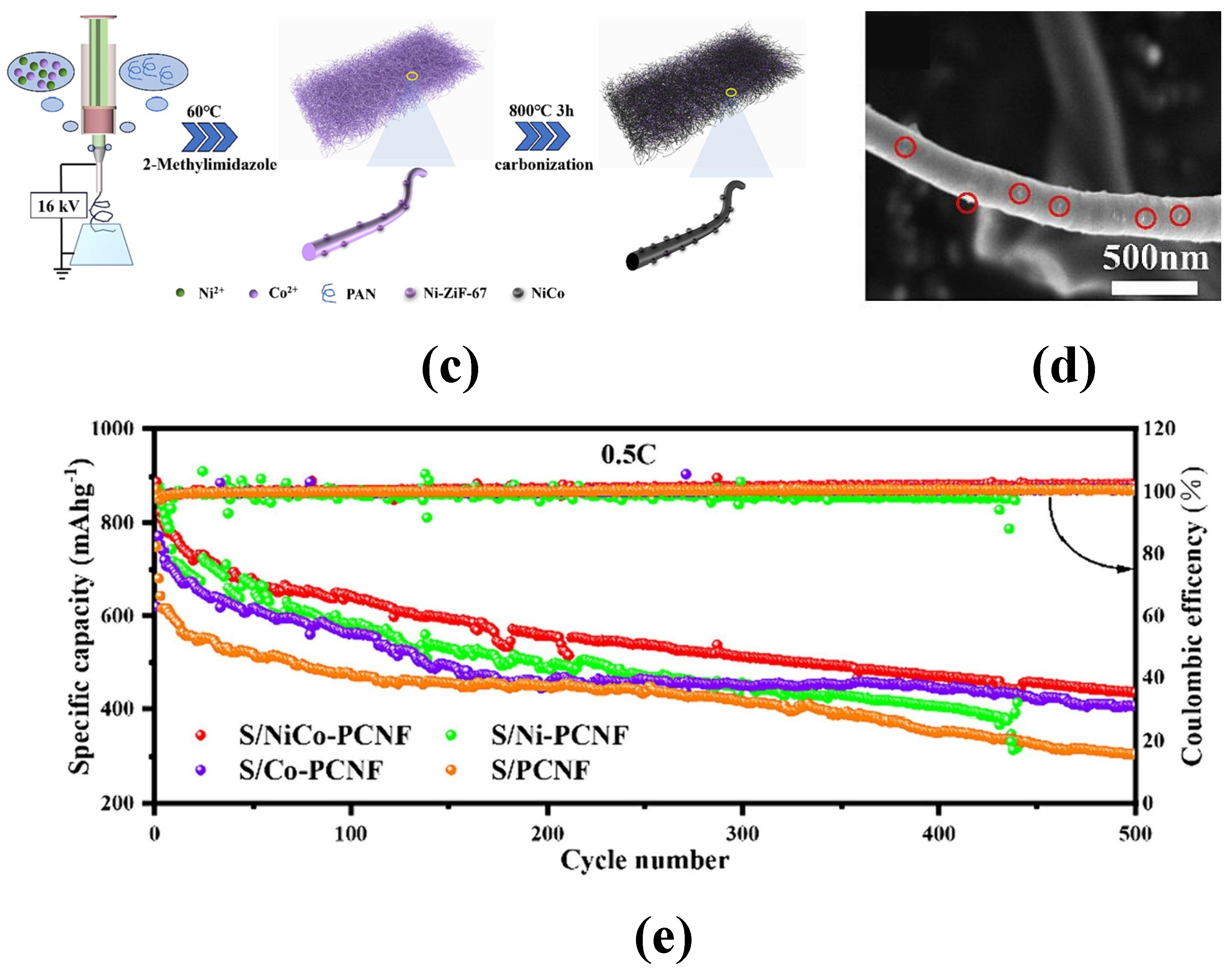
| S/NiCo-PCNF | 1431.7 (0.2 C) | 628.5 (500) | 43.9% | 53.5% | [67] |
| S/Ni-PCNF | 1043.2 (0.2 C) | / | / | / | [67] |
| S/Co-PCNF | 988.7 (0.2 C) | / | / | / | [67] |
| S/PCNF | 836.7 (0.2 C) | / | / | / | [67] |
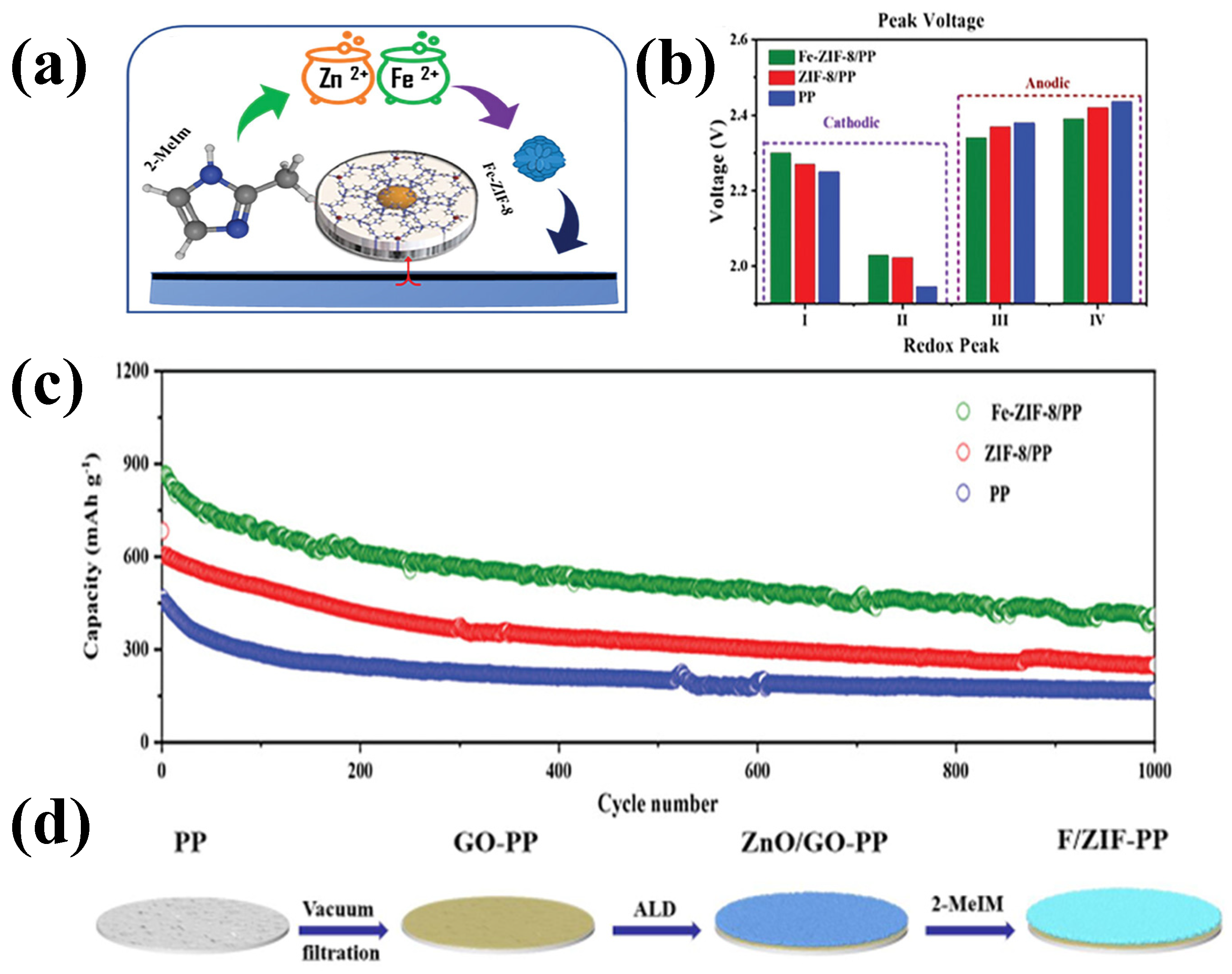
| Fe-ZIF-8/PP | 865 (0.5 C) | 409 (1000) | 47.28% | / | [77] |
| ZIF-8/PP | 683 (0.5 C) | 249 (1000) | 36.46% | / | [77] |
| PP | 466 (0.5 C) | 167 (1000) | 35.84% | / | [77] |
Disclaimer/Publisher’s Note: The statements, opinions and data contained in all publications are solely those of the individual author(s) and contributor(s) and not of MDPI and/or the editor(s). MDPI and/or the editor(s) disclaim responsibility for any injury to people or property resulting from any ideas, methods, instructions or products referred to in the content. |
© 2025 by the authors. Licensee MDPI, Basel, Switzerland. This article is an open access article distributed under the terms and conditions of the Creative Commons Attribution (CC BY) license (https://creativecommons.org/licenses/by/4.0/).
Share and Cite
Zhu, Q.; Sun, W.; Zhou, H.; Mao, D. A Review of Lithium–Sulfur Batteries Based on Metal–Organic Frameworks: Progress and Prospects. Batteries 2025, 11, 89. https://doi.org/10.3390/batteries11030089
Zhu Q, Sun W, Zhou H, Mao D. A Review of Lithium–Sulfur Batteries Based on Metal–Organic Frameworks: Progress and Prospects. Batteries. 2025; 11(3):89. https://doi.org/10.3390/batteries11030089
Chicago/Turabian StyleZhu, Qiancheng, Weize Sun, Hua Zhou, and Deyu Mao. 2025. "A Review of Lithium–Sulfur Batteries Based on Metal–Organic Frameworks: Progress and Prospects" Batteries 11, no. 3: 89. https://doi.org/10.3390/batteries11030089
APA StyleZhu, Q., Sun, W., Zhou, H., & Mao, D. (2025). A Review of Lithium–Sulfur Batteries Based on Metal–Organic Frameworks: Progress and Prospects. Batteries, 11(3), 89. https://doi.org/10.3390/batteries11030089