Article

Improved Self-Assembled Silicon-Based Graphite Composite Anodes for Commercially Viable High-Energy-Density Lithium-Ion Batteries

1
School of Chemical & Environmental Engineering, Liaoning University of Technology, Jinzhou 121001, China
2
Department of Chemistry, Keimyung University, Daegu 42601, Republic of Korea
3
Department of Energy Science and Engineering, DGIST, Daegu 42988, Republic of Korea
*
Author to whom correspondence should be addressed.
Batteries 2025, 11(3), 115; https://doi.org/10.3390/batteries11030115
Submission received: 11 February 2025 / Revised: 11 March 2025 / Accepted: 18 March 2025 / Published: 20 March 2025

Abstract

:
Silicon-based anode materials are used to improve the performance of next-generation high-energy-density lithium-ion batteries (LIBs). However, the inherent limitations and cost of these materials are hindering their mass production. Commercial graphite can overcome the shortcomings of silicon-based materials and partially reduce their cost. In this study, a high-performance, low-cost, and environmentally friendly composite electrode material suitable for mass production was developed through optimizing the silicon content of commercial silicon–graphite composites and introducing a small amount of graphene and carbon nanofibers. This partially overcomes the inherent limitations of silicon, enhances the interface stability of silicon-based materials and the cycle stability of batteries, and reduces the irreversible capacity loss of the initial cycle. At a silicon content of 15 wt%, the initial Coulombic efficiency (ICE) of the battery was 65%. Reducing the silicon content in the composite electrode from 15% to 10% increased the ICE to 70% and improved the first lithiation and delithiation capacities. The battery exhibited excellent cycle stability at a current density of 0.1 A g−1, retaining approximately 65% of its capacity after 100 cycles, good performance at various current densities (0.1–1 A g−1), and an excellent reversible performance.

1. Introduction

With the continuous advancement of science and technology and the increasing demand for clean energy, lithium-ion batteries (LIBs), which are efficient and environmentally friendly energy storage devices, have become an important part of the future energy field. LIB technology is continuously evolving to meet the demands of the growing electric vehicle and renewable energy markets [1,2]. However, LIBs that use traditional graphite anodes can no longer meet the increasing requirements of a high energy density, power density, and safety performance, owing to the low capacity of graphite (372 mAh g−1). Therefore, it is important to develop high-capacity electrode materials. Silicon (Si) has attracted considerable attention as an electrode material owing to its high specific capacity (approximately 4200 mAh g−1), low charge and discharge potential (<0.4 V vs. Li/Li+), environmental friendliness, and abundant reserves. It is considered the most promising among the new generation of negative-electrode materials. Nevertheless, the alloying and dealloying reactions of Si materials during the charge–discharge process are accompanied by huge volume changes (>300%), causing damage to the electrode structure, the pulverization of Si particles, the repeated formation of the solid electrolyte interface (SEI), and the shedding of the active materials during the cycle, leading to a considerable decrease in the performance of the Si anode. In addition, the inherent low electrical conductivity of Si particles (10−5 S cm−1) and slow lithium-ion (Li+) diffusion kinetics (10–14 cm−2 S−1) greatly hinder the widespread application of Si materials in high-capacity LIBs [3,4,5]. Therefore, reducing the internal stress caused by volume expansion and improving the ionic conductivity of the material to achieve long-term cycle stability present urgent research challenges.
To address the above challenges, new modified Si-based anodes were synthesized. These materials are constructed with (1) various nanostructures and voids in the Si main body to relieve internal stress and accommodate huge volume changes, and with (2) three-dimensional structures to form effective channels for Li+ transmission, shortening the Li+ diffusion length and improving the Li+ diffusion kinetics [6,7]. Depositing Si layers on carbon surfaces to construct porous Si–C anodes with carbon nanotubes embedded into micron-size Si and Si-active materials incorporated into carbonaceous products has been extensively studied because carbon materials can minimize electrode deformation and considerably increase Si conductivity [8,9,10]. Researchers have extensively worked toward improving the performance of Si-based batteries. However, several challenges that hinder their use in practical applications arise when moving these batteries from the research phase to the production phase. For instance, high material costs and high technical difficulties have become major problems. The relatively high production cost needs to be effectively solved to meet the needs of large-scale commercial production, and the complexity of the preparation process requires us to continuously improve the structural and electrochemical stability of the material to overcome the technical difficulties. Previous studies have mainly focused on developing new materials and improving existing material structures. However, the battery cycle life, safety, and cost challenges still hinder the use of these materials in commercial applications. In the face of these challenges, future research could focus on reducing costs, optimizing processes, and improving stability, thereby promoting the industrialization of silicon–carbon negative-electrode materials. The development of a high-performance LIB-negative electrode that can be mass-produced remains a significant research challenge [11,12,13].
Herein, we consider the challenges hindering the use of Si-based batteries in practical applications, discussing, in particular, practical battery designs with improved electrode expansion. The development path of silicon-based negative-electrode materials mainly revolves around silicon–carbon and silicon–oxygen composite materials. The preparation of silicon–carbon negative-electrode materials is simple and can be achieved via a range of methods (chemical vapor deposition (CVD) method, mechanical ball-milling method, spray method, magnesium thermal reduction method, sol–gel method, and thermal decomposition method). This material has an excellent theoretical capacity, and could effectively improve the energy density of batteries, so it is widely used. Graphite is widely used in silicon–carbon negative-electrode materials. Graphite is a low-cost commercial carbon material with a high tap density, low surface area, and stable physical and chemical properties, and can considerably reduce the unnecessary decomposition of the electrolyte on the electrode surface while maintaining satisfactory anode integrity. M.G. et al. [14] investigated the relationship between the percentage of Si in a graphite anode and the realization of high-energy-density LIBs. They found that when the electrode composition was Si15Gr75, the cell delivered a high ICE of approximately 82.9%, nearly equivalent to that achieved with a pure graphite anode. Furthermore, the Si15Gr75 Li cell exhibited excellent cyclic stability at a current rate of 0.5 C, retaining approximately 60% of its capacity after 215 cycles. This study paves the way for the development of high-energy-density LIBs by providing valuable insights into the optimization of Si–Gr composite anodes for commercial applications. Owing to the low expansion rate (≤20%) and small free space of graphite-based batteries, an acceptable energy density can be achieved despite their low theoretical specific capacity. However, owing to the larger electrode expansion of Si-based batteries, they require a larger free space than graphite batteries, which reduces the energy density and the advantage of the high specific capacity of Si-based anodes [15,16,17]. Therefore, designing a composite anode by introducing Si–carbon nanomaterials into a mature graphite backbone could be an effective method for mitigating the inherent shortcomings of Si-based and graphite-based anodes and obtaining a satisfactory specific capacity and cycle stability. Graphene is considered an efficient coating material for preparing LIBs owing to its unique structure, high electrical conductivity, high theoretical surface area, and other exceptional properties, providing it with significant potential for energy storage applications. Coating silicon with graphene can slow down the volume change of silicon and form a stable SEI film. However, the introduction of graphene presents another challenge. During the electrode preparation process, the graphene layers can be easily stacked, and it is difficult to ensure the uniform dispersion of the Si nanoparticles (SiNPs) on the graphene surface. The insufficient interpenetration of Li+ between the graphene layers causes the diffusion distance of Li+ through the graphene interlayer channel to increase with the superposition of the electrode size, reducing the Li+ storage performance of the graphene electrode. We discovered that carbon nanofibers (CNFs) can be used to overcome this challenge. CNFs have sp2 hybrid orbitals and a large specific surface area, and they exhibit excellent conductivity, chemical stability, heat resistance, and electrical conductivity, allowing their use in numerous fields [1,11,18,19,20]. Moreover, CNFs have excellent flexibility and structural stability, which can mitigate the Si–graphite negative-electrode problem. In contrast to previous studies, we are focusing on shifting the research on Si–graphite anodes toward practical applications to help achieve the widespread application of Si–graphite anodes in the next generation of mass-produced LIBs.
Herein, a low-cost, environmentally friendly, safe, stable, and high-performance Si–graphite composite electrode produced through a low-cost and simple synthesis process is proposed. In this study, SiNPs were evenly dispersed in an ethanol solution and combined with graphene oxide (GO) through simple physical processes and self-assembly. Next, a small amount of CNFs were dispersed in the mixture to form a multi-channel three-dimensional structure. Finally, the Si@carbon system was introduced into the graphite main chain to form a Si–graphite composite material. The final product was then obtained through multiple processes, such as drying and carbonization. This synthesis strategy does not involve an acid–base treatment, the use of various organic solvents, or a complex synthesis process. Thus, it reduces environmental pollution and experimental costs, avoids adverse effects on the human body, and improves the material performance.

2. Materials and Methods

2.1. Preparing Ni–Mo Binary Catalyst for the Synthesis of CNFs via Chemical Vapor Deposition

Ni–Mo (molar ratio = 6:4) bimetallic catalysts were prepared for the synthesis of CNFs using a coprecipitation method. Aqueous solutions A (nickel nitrate + aluminum nitrate) and B (ammonium molybdate) were thoroughly mixed. Next, the obtained mixture was combined with aqueous solution C (ammonium carbonate), added to distilled water in a dropwise manner, and stirred at room temperature and pH ≈ 9.0 until a precipitate was formed. The obtained solution containing the precipitate was vacuum-filtered and oven-dried at 100 °C for 24 h. The dried precipitate was then ground and collected as a powder to be used as a metal catalyst for the synthesis of CNFs. Details of the method used to prepare the catalyst are shown in Figure S1. Aluminum nitrate was used as a support for the transition metal catalyst, ammonium molybdate was used to inhibit the aggregation of the transition metal particles between particles during the reaction at high temperatures, and ammonium carbonate was used as a precipitant.
The CNF synthesis method is shown in Figure S1. Acetylene (C2H2), H2, and Ar gases were used as the carbon source to synthesize the CNFs, promoting the production of gas and carrier gas, respectively. The prepared Ni–Mo catalyst powder was spread evenly on a quartz boat and placed in a tube furnace reactor. The temperature was then increased to 700 °C at a rate of 10 °C min−1 while maintaining the Ar gas flow. After reaching the target synthesis temperature, the Ar gas was replaced with H2/Ar mixed gas (10%) to reduce the catalyst for 30 min. Next, C2H2 gas and the H2/Ar mixed gas were passed to the reactor for 1 h. Finally, the reduced metal catalyst was slowly cooled to room temperature while eliminating the supply of other gases and maintaining the Ar gas flow.

2.2. Synthesis of the Si@G/CNF/Graphite Composites

The process used to synthesize the Si@G/CNF/graphite composites is shown in Figure 1. SiNPs (20 mg, APS ≤ 50 nm, 98%, Alfa Aesar, Inc., Ward Hill, MA, USA) were uniformly dispersed in ethanol (200 mL) by sonication for 2 h. Then, GO solution (40 mL, N002-PS, 0.5%, Angstron Materials, Dayton, OH, USA) was added to the above solution under vigorous magnetic stirring for 1 h. The mixed dispersion was then sonicated for 2 h to obtain the Si/GO mixture. Next, CNFs (0.2 g) were added to the mixture under stirring for 1 h and then sonicated for 2 h to obtain a stable Si/GO/CNFs dispersion. A certain amount of graphite (powder, <20 μm, synthetic, Sigma-Aldrich, St. Louis, MO, USA) was mixed into the dispersion under magnetic stirring, and the mixture was then sonicated for 2 h. The resulting composites were collected via centrifugation and dried at 80 °C for 24 h in a vacuum oven. The final product was transferred to a quartz tube furnace and heated to 700 °C at a rate of 10 °C min−1, and the argon atmosphere flow was maintained for 5 h to obtain thermally reduced Si@G/CNF/graphite composites to be used as anode-active composite materials for LIBs (Figure 1).
To optimize the electrochemical properties of the obtained materials, the mass ratio of graphite to the Si/G/CNF composite was changed, and the same method was used to prepare the Si@1-G/CNF/graphite (15:75, wt%) and Si@2-G/CNF/graphite (10:80, wt%) composite materials shown in Table 1.

2.3. Material Characterization

The surface morphologies and microstructures of the Si@G/CNF/graphite composites were characterized using field-emission scanning electron microscopy (FE-SEM, S-4800, Hitachi, Tokyo, Japan) and high-resolution transmission electron microscopy (HR-TEM, JEM-2100, JEOL, Tokyo, Japan). The qualitative and quantitative analyses of the elements in the prepared samples were performed using energy-dispersive X-ray spectroscopy (EDS) mapping (ARL-3460, Thermo Fisher Scientific, Waltham, MA, USA). The sample composition and crystal structure were characterized using powder X-ray diffraction (XRD, Ultima IV, Rigaku, Tokyo, Japan) with a 2 kW system and Cu-Kα radiation (K = 1.5418 Å) at a 2θ range of 2–90°. Raman spectroscopy was conducted on a LABRAM HR-800 (Horiba Jobin-Yvon, Paris, France) with a laser light (λ = 514 nm) in the wave number range of 100–3000 cm−1. The Si, reduced GO (rGO), CNFs, and graphite contents in the composites were determined using thermogravimetric analysis (TGA, Diamond TG-DAT 8122 thermal analyzer system, Perkin Elmer, Waltham, MA, USA). In this test, the samples were heated from 25 °C to 800 °C at a rate of 10 °C min−1 under air atmosphere. Fourier-transform infrared spectroscopy (FTIR, Nicolet 6700 FTIR spectrophotometer, Nicolet, Madison, WI, USA) was used to analyze the changes in the surface functional groups of the samples, employing KBr pellets tested in the frequency range of 4000–500 cm−1. The chemical bonding states were determined using X-ray photoelectron spectroscopy (XPS, Multilab-2000, Thermo Fisher Scientific, Waltham, MA, USA) with a twin anode and Al-Kα radiation as the X-ray source.

2.4. Cell Fabrication and Characterization

The anode slurry was prepared by dissolving the appropriate weight ratios of the active material (Si@G/CNF/graphite, 90 wt%), conductive carbon (Super P, 5 wt%), and the binder (polyvinylidene fluoride, 5 wt%) in N-methyl pyrrolidone solvent. To achieve a homogeneous mixture, the resulting viscous liquid was thoroughly stirred. Next, the slurry was cast onto a copper (Cu) current collector foil (thickness = 11 μm) and dried in a heating oven at 80–100 °C for 12 h. The dried electrode sheet was then punched into circular electrodes (diameter = 14 mm) for further processing. The cathode slurry was prepared in an N-methyl pyrrolidone solvent by incorporating the requisite quantities of the active material, conductive carbon (Super P), and the binder (PVDF). The slurry casting procedure and subsequent steps were the same as those used for the anode. Similarly, the dried cathode sheet was punched into electrodes (diameter = 14 mm) for cell assembly and electrochemical evaluation.
For the electrochemical characterization, coin-type (CR2032) button cells were assembled in an argon-filled glovebox with oxygen at a moisture level of less than 0.5 ppm. In the half-cells, Si@G/CNF/graphite acted as the working electrode, and lithium metal was used as both the counter and reference electrodes. A LiPF6 solution (1 M) dissolved in a mixture of ethylene carbonate and dimethyl carbonate was used as the electrolyte in all cell types. The electrodes were separated by a polypropylene membrane. Cyclic voltammetry (CV) and galvanostatic charge–discharge measurements were obtained at room temperature (25 °C) using an electrochemical workstation and a battery tester (Neware Co., Ltd., Shenzhen, China) at a scan rate of 0.1 mV‧s−1 and a voltage range of 0.01–1.5 V (vs. Li/Li+). The charge–discharge profiles of each composite electrode were measured for 100 cycles. Electrochemical impedance spectroscopy (EIS) measurements were conducted using a CHI 660D electrochemical analysis instrument (CH Instruments, Inc., Shanghai, China) at a frequency range of 100 kHz–0.01 Hz and an amplitude of 5 mV.

3. Results and Discussion

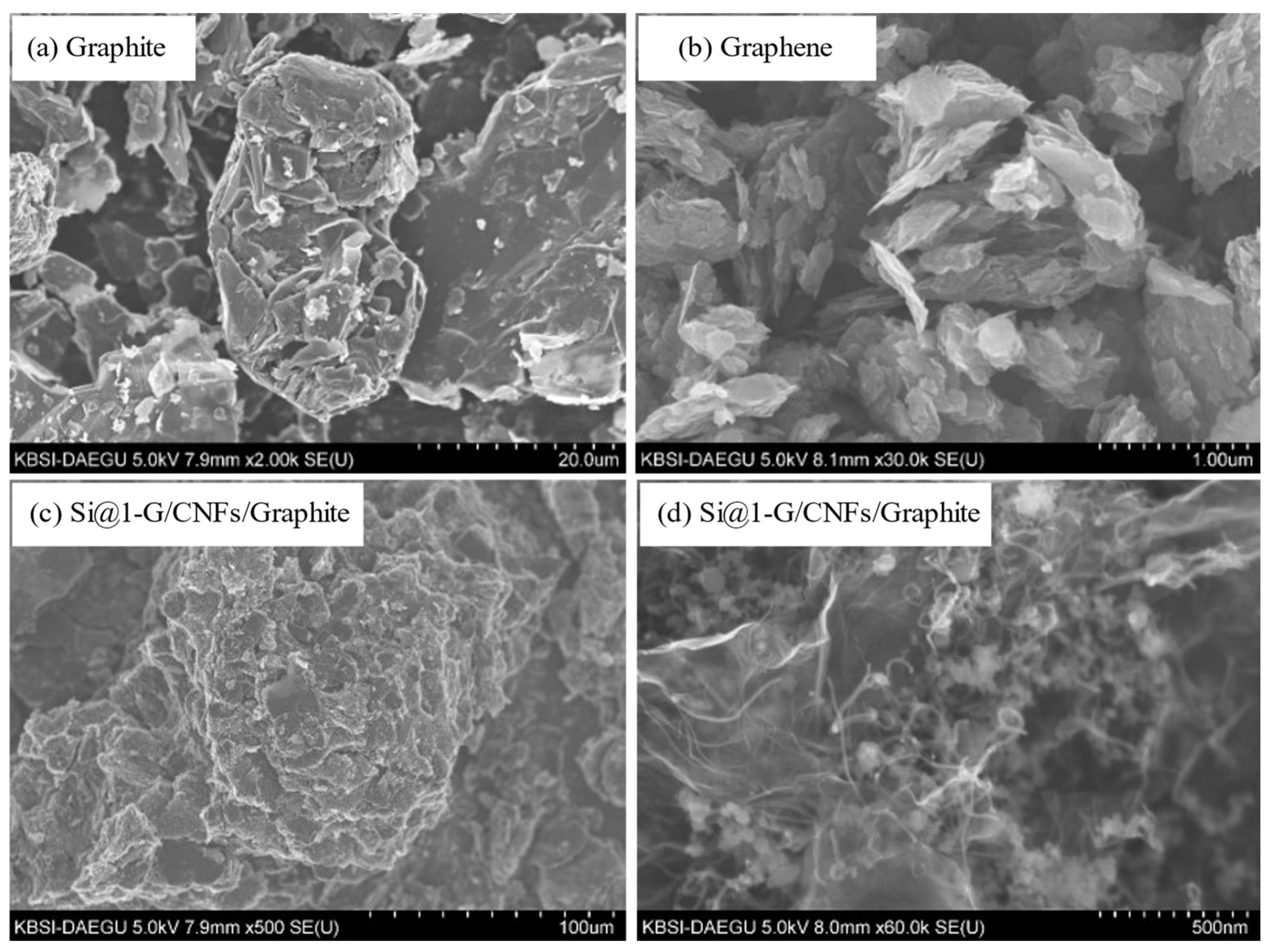
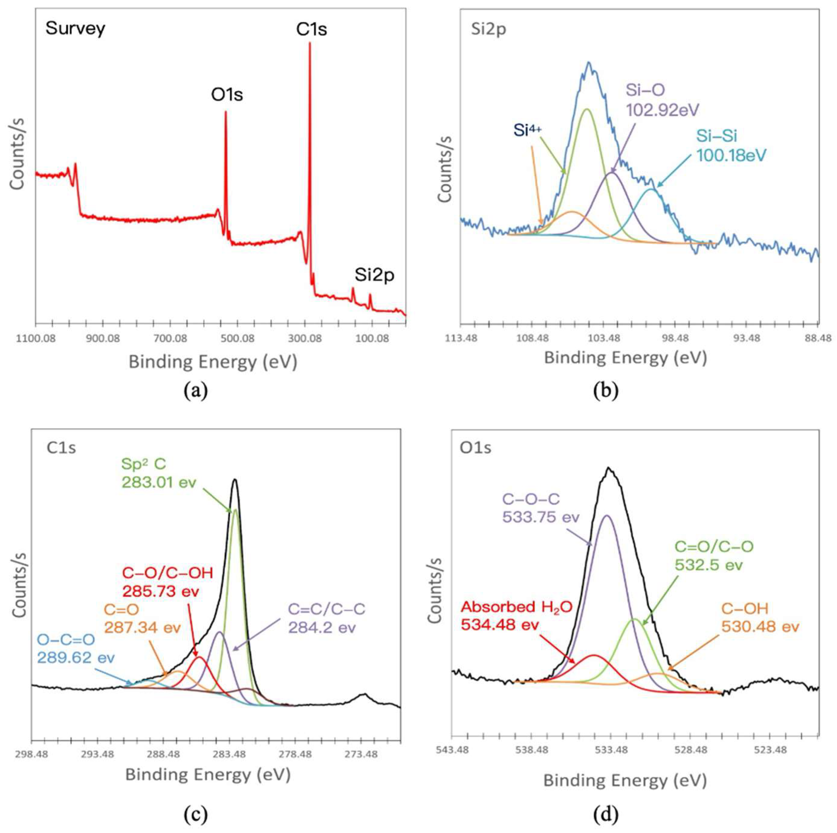
3.1. Structural and Morphological Characterizations of the Si@1-G/CNF/Graphite Composites

Figure 2 shows the SEM images of graphite, graphene, and the CNF/graphite Si@1-G/CNF/graphite composite. In addition, the atomic content ratio was determined based on the EDS spectrum of Si@1-G/CNF/graphite (Figure S2). Figure 2a shows the morphology of natural graphite. The image shows the clear flake-like layered structure characteristic of natural graphite, with numerous gaps between the flake structures. Figure 2b shows the morphological characteristics of the multilayer graphene, with a flaky structure and visible wrinkles on the surface. Figure 2c,d show the morphology of Si@1-G/CNF/graphite at different magnifications. Figure 2d shows smooth-surfaced slender fibers intricately entangled on the surfaces of graphite and graphene and tightly interspersed between the materials to form an intertwined three-dimensional network structure. These slender fibers are CNFs, and the round granular substances are SiNPs [21,22]. This structure can provide an effective buffer for the volume change in the electrode during the lithiation process, preventing electrode damage through volume expansion, which maintains the structural stability of the electrode material. Moreover, the three-dimensional network structure can reduce the transmission distance of the electrons and ions, effectively decreasing the transmission resistance during the cycle.
The HR-TEM images of the Si@1-G/CNF/graphite composites (Figure 3) were analyzed to further clarify their morphological and structural characteristics. Figure 3a,b show clear gaps between the layered structures. The lattice distances of graphite, which corresponded to the crystal plane spacing of (002) and (100) between two adjacent carbon atoms, were determined, based on Figure 3b, to be 0.351 and 0.2152 nm, respectively. The graphene image (Figure 3d) illustrates a similar lattice spacing between the carbon atoms. The morphological images of Si@1-G/CNF/graphite (Figure 3e,f) clearly show that the SiNPs were wrapped with wrinkled graphene and that the flaky graphite and CNFs were evenly distributed in the system. The encapsulation provided by the graphene layer can compensate for the volume change in the silicon particles and effectively prevent direct contact between silicon particles and the electrolyte solution, inhibiting excessive SEI film formation. The interwoven network structure formed among the CNFs, graphite, and graphene maintained the integrity of the electrode structure during the charge–discharge process, and the gaps formed by the network structure increased the specific surface area of the material, providing more effective channels for the transmission of ions, which improved the conductivity of the material. High conductivity, low resistivity, and good structural stability are key to maintaining the high specific capacity and excellent cycle performance and rate performance of anode materials [23]. In addition, Figure 3g,h show the typical lattice spacing between the carbon atoms as well as a lattice spacing of 0.313 nm, corresponding to the Si (111) of the SiNPs.
XRD was used to investigate the crystal structures of the individual components and the prepared composites (Figure 4a). In the diffraction curve of GO, a strong and broad representative diffraction peak was observed at 2θ = 12°. However, this representative peak disappeared in the diffraction pattern of the composite material, which can be attributed to the disappearance of the intrinsic –C–O–C–, C=O, –OH, and –COOH on the basal plane and the edges of GO owing to thermal reduction. Next, a strong peak was observed at 2θ = 26°, which is the characteristic peak of the (002) crystal plan of amorphous carbon and related to the layered structure of the crystal [24,25]. The removal of the oxygen-containing functional groups resulted in a decrease in the interlayer spacing between the stacked GO sheets, which changed the diffraction angle. This characteristic peak also appeared in the graphite and CNFs. In the diffraction results of the composite, the diffraction peak attributed to the (002) plan of graphite was observed at 2θ = 26° and the secondary peak of the (101) plan, which is related to the crystal orientation, was observed at 2θ = 44.6°, confirming the presence of carbon components in the composite. In addition, strong diffraction peaks were observed in the diffraction pattern of Si at 2θ = 28.4°, 47.3°, 56.1°, 69.1°, and 76.4°, corresponding to the typical (111), (220), (311), (400), and (331) planes of face-centered cubic Si crystals [23,26,27]. These representative Si diffraction peaks indicate that the synthesis process did not change the lattice structure of the composite components. Thus, these results confirm the presence of all components in the composite and that their structures were not changed by the synthesis process.
To further investigate the microstructure of the composites, the degree of graphitization was evaluated based on the material internal defects. In the Raman spectra (Figure 4b), all samples exhibited a characteristic sp3 hybrid disordered D band at approximately 1350 cm−1 and a G band associated with the sp2 hybrid ordered carbon structure at approximately 1580 cm−1 [28,29,30]. The relative intensity ratio of the D and G bands (ID/IG) reflects the degree of graphitization, the defect density, and the size of the graphitized area. The increase in the ID/IG value of GO from 0.84 to 0.85 after its thermal reduction to rGO is attributed to the increase in the number of O-terminated sp2 carbon edge atoms, resulting in a decrease in the in-plane sp2 graphitic domains [31]. The intensity of the G band in the composite was considerably higher than that of the D band. These results, combined with the curve characteristics of graphite, indicate the low defects and disorder of the composite material, suggesting that the material has all the graphite properties as well as good crystallinity.
The surface composition and chemical bonding state of each element in the Si@1-G/CNF/graphite composites were characterized using XPS (Figure 5). The figure shows the XPS high-resolution Si 2p, C 1s, and O 1s spectra of the composites. The XPS survey spectra of the composites (Figure 5a) showed strong O 1s and C 1s peaks, which were mainly due to the presence of highly graphitized lattices attributed to the graphite and graphene. The peak of Si 2p was relatively weak, indicating that the Si particles were encapsulated in the rGO sheets and that the surface was covered by the carbon layer. Figure 5b shows the high-resolution Si 2p spectra of the composites. The signal had two different peaks at 100.18 and 102.92 eV, which are attributed to bulk silicon (Si–Si) and oxygen-bonded silicon (Si–O), respectively [32,33], indicating that during the material preparation process, a small number of SiNPs exposed to the air underwent surface oxidation under certain conditions to produce a small amount of SiOx. Because the surface was covered by SiOx and carbon layers, the Si–Si peak of the Si particles was slightly lower than the Si–O peak. As shown in Figure 5c, the C 1s spectra of the composite showed two strong peaks at 284.2 and 285.73 eV, corresponding to the C–C/C=C in the aromatic ring and the C–O bonds in the carboxyl and epoxy groups, respectively [23,34]. In addition, the C 1s signals of the composites all had strong C–C/C=C peaks, whereas the peak intensity of the O-containing groups decreased considerably, which can be attributed to the removal of O atoms during the heat treatment (Figure S3). Two weak peaks at approximately 289.62 and 287.34 eV, which are attributed to the O–C=O bond in the –COOH groups in graphite and graphene, were also observed on the surface of the composite. Moreover, the high-resolution O 1s XPS spectra (Figure 5d) confirmed the presence of –COOH functional groups in the composite.
Figure 6a shows the thermogravimetry/differential thermal analysis (TG/DTA) of the two composite materials during continuous combustion under ambient conditions until the temperature cutoff point of 800 °C. The TG/DTA curves can be divided into four stages according to the different components of the composite materials, and the detailed analysis results are shown in Figure S4. The exothermic peaks of Si@1-G/CNF/graphite and Si@2-G/CNF/graphite started with the first weight loss at 400–450 °C, which corresponded to the decomposition of the graphene component in the composites [35]. In this stage, most O atoms in the composite material were eliminated from the GO layer. The second stage corresponded to the thermal decomposition of the CNF under an air atmosphere. The third stage was the rapid decomposition of the graphite component. Thus, the total C content in Si@1-G/CNF/graphite was approximately 79 wt%, whereas the total carbon content in Si@2-G/CNF/graphite was approximately 82 wt%, which corresponded to Si:C weight ratios of 15:75 and 1:80 during the composite manufacturing process, respectively. The slight difference in the data is attributed to a small amount of Si loss during the thermal reduction process and trace impurities on the surface of the composite. In addition, the weight of the fourth stage increased after the temperature reached 800 °C, which is attributed to the oxidation of the remaining Si component to SiOx under the air atmosphere [23,36]. This was due to the direct contact between the carrier gas and the exposed Si after the decomposition of the surface carbon at high temperatures. This result is in good agreement with the XPS of Si 2p. Measuring the total C and Si contents accurately can be challenging because of the possible weight loss of the sample during annealing or thermal reduction. Nevertheless, carbon materials, including graphene and CNFs, are typically combusted and become depleted at 400–800 °C, whereas Si remains stable. Therefore, the differences in the composite contents could be detected based on a rapid reduction in the weight of the sample.
To further verify the surface chemical structure of the prepared samples, FTIR analysis was conducted, the results of which are presented in Figure 6b. The figure shows the FTIR spectra of the composite before and after the heat treatment and annealing. Through comparison, the peak intensities of the O=C=O and C=O oxygen-containing groups (2375.64 and 1870.0 cm−1, respectively) were found to considerably decrease, owing to the reduction in some oxygen-containing groups after heat treatment [37,38]. The vibration peak at 932.69 cm−1 corresponded to the asymmetric stretching and bending of the siloxane group. The appearance of this peak was related to the oxidation of the surface of the SiNPs and the generation of a small amount of SiOx, which is in good agreement with the previous XPS results. The multiple-vibration peak at approximately 800 cm−1 was the strongest characteristic peak of the Si–C bond, indicating an extremely tight bond between the silicon atoms and the carbon atoms, with high chemical and thermal stability. This suggests that the SiNP surface was successfully and tightly entangled with the carbon layer. Moreover, numerous peaks related to the O-containing functional groups were observed in the spectra. A broad peak was observed at approximately 3400 cm−1, which corresponded to the stretching mode vibration of the O–H group superimposed on the O–H stretching of the carboxylic acid (R–COOH), owing to the presence of water molecules and alcohol groups. The peak at approximately 1827 cm−1 is attributed to the C=O stretching of the –COOH group, and the peak at 1103 cm−1 corresponds to the C–O stretching vibration of the C–O–C bond [39,40]. These results demonstrate the successful preparation of the Si@G/CNF/graphite composite.

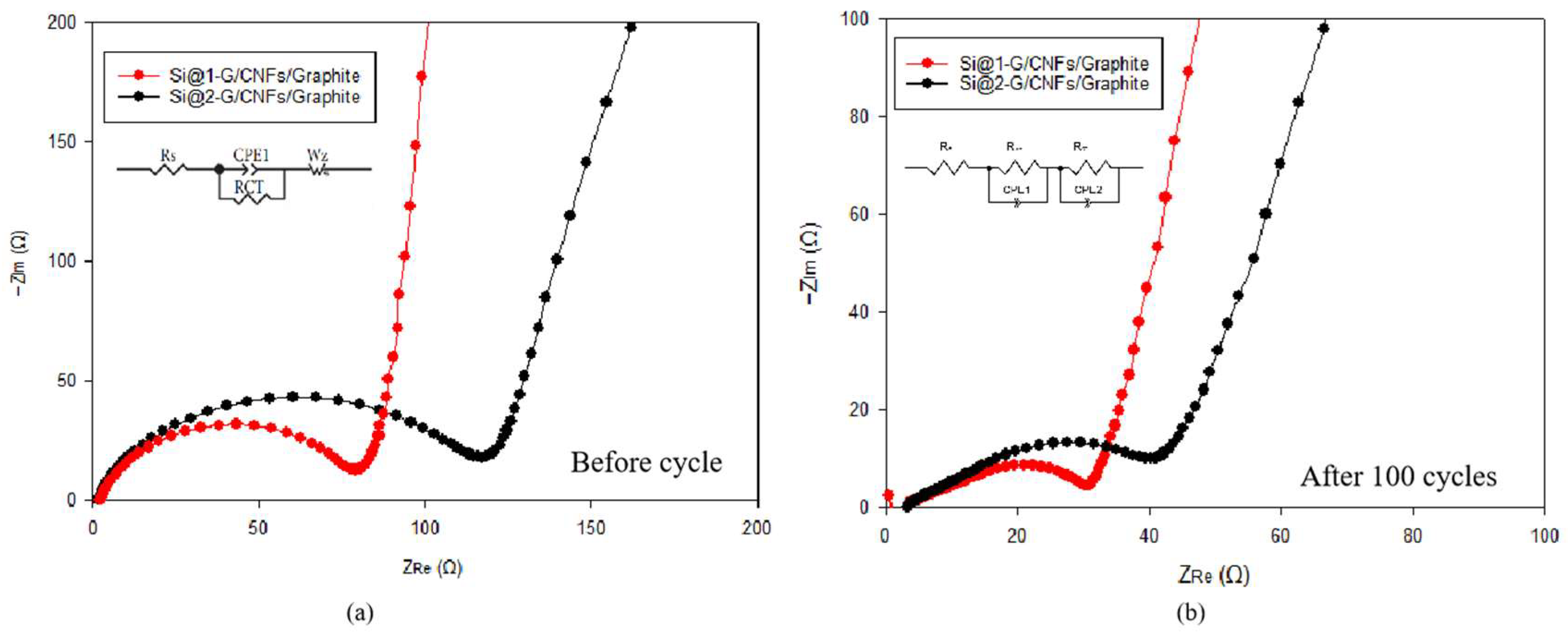
3.2. Electrochemical Performance

Figure 7 demonstrates the CV curves of the fabricated coin cell using Si@1-G/CNF/graphite (Figure 7a) and Si@2-G/CNF/graphite (Figure 7b) during the initial five cycles at 0.01–1.5 V (vs. Li+/Li) at a scan rate of 0.1 mV s−1. During the first cathodic scan (lithiation process) of Si@1-G/CNF/graphite, two distinct peaks were observed at 0.32 and 0.70 V. Similarly, two cathodic peaks were observed in the initial CV curves (at 0.32 and 0.75 V) of Si@2-G/CNF/graphite. The two reduction peaks in the cathode branch of the CV curve are attributed to the conversion of bulk Si into LixSi alloy and other lithiated precipitates (LixSiOy, Li2CO3, and Li2O) [23,41,42]. The sharp peak that appeared during the reduction process around 0.2V is a typical peak of graphite anode related to the embedding of lithium ions into the graphite interlayer. In addition, the broad peak related to SEI at around 0.8V overlapped with the broad peak caused by Si alloying. These materials were generated via a series of irreversible multi-step electrochemical reactions between Si and Li+, which is in good agreement with previous electrochemical studies. In the first cathodic scan, a weak peak was observed at approximately 1.0 V for both electrodes, which can be attributed to the reaction between the electrode material and the electrolyte, resulting in the formation of an irreversible SEI layer on the electrode surface during the discharge process. However, this peak disappeared in the subsequent cycles, and the CV curve in the second cycle overlapped with the CV curve in the subsequent cycles, further confirming that the effective combination of SiNPs and carbon materials enhances the reversibility and cycle stability of electrode materials. In addition, during the anodic scan (delithiation process) in the first cycle, two broad oxidation peaks were observed at 0.52 and 0.33 V in Si@1-G/CNF/graphite and at 0.53 and 0.30 V in Si@2-G/CNF/graphite. These peaks corresponded to the partial decomposition of the highest lithiated phase and the complete delithiation of the LixSi alloy into amorphous Si, respectively. The strong reduction peak at 0.01–1.2 V in the cathodic scan corresponded to the amorphous LixSi alloy formed by amorphous SiNPs during the reversible Li+ insertion–deinsertion process [23,43]. With the increase in the number of scans, a gradual and steady increase in the intensity of the oxidation peak was observed because the composite electrode material was gradually activated during the cycle, indicating the tendency of Li+ to form alloys with SiNPs, which increases the ionic conductivity. During the oxidation process, the curve tended to be stable starting from the second cycle, and the splitting phenomenon of the oxidation peak weakened, indicating that the SEI film tended to be stable. The phase transformation results for Si and C during the first five cycles are summarized in Table S1.
The electrochemical performance of Si@1-G/CNF/graphite and Si@2-G/CNF/graphite was evaluated for 100 cycles at a low current density (100 mA g−1, Figure 8a), and the corresponding constant current curves are shown in Figure 8b. The discharge specific capacities of Si@1-G/CNF/graphite and Si@2-G/CNF/graphite were 521.1 and 558.7 mAh g−1, respectively, in the initial cycle, after which they considerably decreased owing to the inability of the electrode to accommodate the volume change in the SiNPs during lithiation–delithiation and the formation of an SEI layer on the electrode surface when the SiNPs came into contact with the electrolyte. In addition to a low initial charge capacity, Si@1-G/CNF/graphite and Si@2-G/CNF/graphite exhibited low ICEs of 65.0% and 70.0%, respectively. This can be attributed to the irreversible SEI layer formed by the decomposition reaction at the electrode–electrolyte interface, during which Li+ was consumed, leading to inevitable capacity loss. The Coulombic efficiency (CE) of Si@1-G/CNF/graphite and Si@2-G/CNF/graphite sharply increased to 92.1% and 93.3%, respectively, during the second cycle and stabilized in the subsequent cycles, reaching 99.0% after 100 cycles. After 100 cycles, the capacities of the Si@1-G/CNF/graphite and Si@2-G/CNF/graphite electrodes stabilized at 309.3 and 301.5 mAh g−1, respectively, and their capacity retention rates reached 65% and 54%, respectively. To further verify the electrochemical performance of the composite materials, Figure 8c shows the rate performance of the Si@1-G/CNF/graphite and Si@2-G/CNF/graphite electrodes in the current density range of 0.1–1 A g−1. The Si@1-G/CNF/graphite electrode exhibited a rate performance superior to that of the other electrodes at all current densities. The reversible capacities of the Si@1-G/CNF/graphite electrode were 568.5, 423.3, 373.3, 346.3, 336.2, and 332.3 mAh g−1 at current densities of 0.1, 0.2, 0.5, 1, 0.5, 0.2, and 0.1 A g−1, respectively. When the current density was restored to 0.1 A g−1, the reversible capacity shifted to 346.7 mAh g−1, and the electrode exhibited a better cycle and rate performance overall, confirming the high cycle stability and reversibility of the Si@1-G/CNF/graphite electrode. With the increase in the silicon (wt%) content, the initial capacity loss increased, and the change in the lithiation and delithiation capacity considerably affected the ICE of the electrode, which is an important consideration for material commercialization. In previous studies, Si15 Gr75 batteries exhibited a capacity of approximately 70 mAh g−1 at a current density of 740 mA g−1. However, our work demonstrated strong advantages in terms of the ICE and capacity retention after multiple cycles. These results indicate that graphite alone is not sufficient to compensate for the changes in silicon that occur during lithiation–delithiation processes. Moreover, doping with a small amount of graphene and CNFs effectively improved the conductivity of the electrode, resulting in the excellent cycle performance and rate performance of the electrode.
To understand the effect of the SEI and charge transfer resistance on the electrochemical performance of the materials, EIS spectra were acquired after 100 charge and discharge cycles (Figure 9). The inset in the Nyquist plot shows the equivalent circuit model of the assembled half-cell. The circuit model takes into account the resistance caused by the interaction between the electrolyte and the Si particles (Rs), the resistance caused by the migration of Li+ between the electrodes through the SEI layer (RSEI), the resistance during charge transfer (RCT), and the Warburg impedance (Wz) [23,44,45,46]. To observe the Nyquist plots of the two composites before cycling (Figure 9a) and after 100 cycles (Figure 9b), we obtained the Nyquist plots before cycling (Figure 9a) and after 100 cycles and evaluated the Li+ storage performance of the electrodes. The Nyquist plots of each composite material before cycling contain a semicircle in the mid-frequency region, which represents the charge transfer resistance (RCT) between the electrode and the electrolyte, and an inclined line in the low-frequency region. The diameter of the semicircle was the sum of the resistance of Li+ to passing through the insulating SEI layer on the surface of the active material (RSEI) and RCT, whereas the inclined line was directly related to the tortuosity of Li+ diffusion. The Nyquist plots of the two composites before cycling (Figure 9a) show similar curve characteristics. Compared with the Si@2-G/CNF/graphite electrode (RCT = 117.6 Ω), the Si@1-G/CNF/graphite electrode (RCT = 78.5 Ω) exhibited a lower resistance. The resistance value of the composite electrode largely depends on the content of the SiNPs. To further evaluate the stability of the formed SEI film, the Nyquist plots were obtained after 100 cycles. The RSEI values of Si@1-G/CNF/graphite and Si@2-G/CNF/graphite were 30.5 and 40.2 Ω, respectively. The lower resistance of Si@1-G/CNF/graphite is attributed to the formation of a stable SEI film on the surface of the SiNPs, which can prevent direct contact between the active materials and the electrolyte, thereby minimizing the decomposition of the electrolyte. After 100 cycles, the diameter of the Si@1-G/CNF/graphite semicircle was small, indicating that the transfer resistance of the Si@1-G/CNF/graphite electrode becomes smaller, so it can quickly transfer electrons and ions, effectively improving the ion–electron conductivity and reducing the charge transfer resistance. However, the electrode materials with more carbon content show a larger resistance, which is because the excessive carbon material considerably hinders the effective transmission of ions and electrons, resulting in higher resistance and a lower Li+ diffusion rate. An appropriate silicon–carbon ratio induces the dispersion of carbon materials, minimizing the agglomeration of the SiNPs, providing an effective coating, and maintaining the structural integrity of the electrode during continuous cycling. The above results show that the Si@1-G/CNF/graphite electrode exhibited excellent performance, making it a promising anode material.

4. Conclusions

This study investigated the addition of appropriate amounts of silicon, graphene, and CNFs to existing commercial graphite anodes to improve their properties. The composite electrode was prepared using a simple physical mixing and low-temperature thermal reduction process. The reversible specific capacity was further improved without sacrificing the ICE and cycling stability. The developed multicomponent composite electrode exhibited superior performance at the half-cell level compared with pure graphite, pure silicon, and silicon/graphite binary composite electrodes. The results show that the composite electrode with a silicon content of 15 wt% exhibited a better capacity retention rate (60%) after 100 cycles. This can be attributed to the secondary carbon layer protection of the SINPs by graphene and CNFs, which mitigated the inherent volume change of the silicon, effectively reduced the contact between the silicon surface and the electrolyte, and stabilized the formation of the SEI layer. This study provides a low-cost and green electrode synthesis method that produces high-performance electrodes and has great potential in battery manufacturing. This synthesis method is promising for advancing effective theoretical support for the commercial use of silicon/carbon electrodes. Thus, this study paves the way for the development of high-energy-density LIBs and provides valuable technical support for optimizing silicon-based graphite composite anodes to achieve commercial feasibility. Future research work needs to focus on reducing costs, optimizing processes, and improving the production efficiency and structure and composition of silicon–carbon negative-electrode materials. The focus here should be on improving stability, strengthening the cooperation between industry, academia, and research teams, and jointly promoting the research and development of silicon–carbon anode materials, thereby accelerating its industrialization process from the laboratory to the market.

Supplementary Materials

The following supporting information can be downloaded at https://www.mdpi.com/article/10.3390/batteries11030115/s1. Figure S1: process for preparing the catalysts and the synthesis of carbon nanofibers; Figure S2: EDS spectrum of Si@1-G/CNF/graphite composite; Figure S3: high-resolution XPS of O 1s of the Si@1-G/CNF/graphite composite; Figure S4: TGA/DTA curves of Si@1-G/CNF/graphite and Si@2-G/CNF/graphite. Table S1: Summary of the phase changes of Si and C during the first five cycles; Table S2: Comparison of this work with other previous studies in terms of Discharge capacity, Coulombic efficiency, and Capacity retention.

Author Contributions

R.C. designed and performed the experiments, provided the concepts and methodology required for the experiments, organized the data, and wrote the main manuscript text. D.-E.J. and H.-H.P. prepared the samples, performed the experiments, and designed the figures using the relevant software. J.J., Y.-Y.J. and H.L. participated in the electrochemical measurements and validation of the relevant data. C.-S.L., as the corresponding author, was responsible for the review and submission of the manuscript. All authors reviewed and analyzed the manuscript. All authors have read and agreed to the published version of the manuscript.

Funding

This research was funded by a grant from the Korea Evaluation Institute of Industrial Technology (grant number: 20018434).

Data Availability Statement

The datasets generated during and/or analyzed during the current study are available from the corresponding author upon reasonable request.

Conflicts of Interest

The authors declare no conflicts of interest.

Abbreviations

The following abbreviations are used in this manuscript:
LIBsLithium-ion batteries
SEISolid electrolyte interface
CFTsCarbon nanofibers
CVDChemical vapor deposition
GOGraphene oxide
SEMScanning electron microscopy
TEMTransmission electron microscopy
EDSEnergy-dispersive X-ray spectroscopy
XRDX-ray diffraction
XPSX-ray photoelectron spectroscopy
PVDFPolyvinylidene fluoride
CVCyclic voltammetry
EISElectrochemical impedance spectroscopy
RCTCharge transfer resistance
ICEInitial Coulombic efficiency
CECoulombic efficiency

References

  1. Mishra, G.K.; Gautam, M.; Bhawana, K.; Ghosh, J.; Mitra, S. High energy density lithium-ion pouch cell with modified high voltage lithium cobalt oxide cathode and graphite anode: Prototype stabilization, electrochemical and thermal study. J. Power Sources 2023, 580, 233395. [Google Scholar] [CrossRef]
  2. Tubtimkuna, S.; Sawangphruk, M.; Duriyasart, F. Effect of electrolyte additives on cycling performance of 18650 graphite//nmc811 Li-ion batteries. ECS Trans. 2020, 97, 155–166. [Google Scholar] [CrossRef]
  3. Duan, J.; Tang, X.; Dai, H.; Yang, Y.; Wu, W.; Wei, X.; Huang, Y. Building safe lithium-ion batteries for electric vehicles: A review. Electrochem. Energ. Rev. 2020, 3, 1–42. [Google Scholar] [CrossRef]
  4. Asenbauer, J.; Eisenmann, T.; Kuenzel, M.; Kazzazi, A.; Chen, Z.; Bresser, D. The success story of graphite as a lithium-ion anode material—Fundamentals, remaining challenges, and recent developments including silicon (oxide) composites. Sustain. Energy Fuels 2020, 4, 5387–5416. [Google Scholar] [CrossRef]
  5. Chae, S.; Ko, M.; Kim, K.; Ahn, K.; Cho, J. Confronting issues of the practical implementation of Si anode in high-energy lithium-ion batteries. Joule 2017, 1, 47–60. [Google Scholar] [CrossRef]
  6. Chen, Y.; Kang, Y.; Zhao, Y.; Wang, L.; Liu, J.; Li, Y.; Liang, Z.; He, X.; Li, X.; Tavajohi, N. A review of lithium-ion battery safety concerns: The issues, strategies, and testing standards. J. Energy Chem. 2021, 59, 83–99. [Google Scholar] [CrossRef]
  7. Lavigne Philippot, M.; Costa, D.; Cardellini, G.; De Sutter, L.; Smekens, J.; Van Mierlo, J.; Messagie, M. Life cycle assessment of a lithium-ion battery with a silicon anode for electric vehicles. J. Energy Storage 2023, 60, 106635. [Google Scholar] [CrossRef]
  8. Yang, Z.; Wu, C.; Li, S.; Qiu, L.; Yang, Z.; Zhong, Y.; Zhong, B.; Song, Y.; Wang, G.; Liu, Y. A unique structure of highly stable interphase and self-consistent stress distribution radial-gradient porous for silicon anode. Adv. Funct. Mater. 2022, 32, 2107897. [Google Scholar] [CrossRef]
  9. Wang, W.; Wang, Y.; Yuan, L.; You, C.; Wu, J.; Liu, L.; Ye, J.; Wu, Y.; Fu, L. Recent advances in modification strategies of silicon-based lithium-ion batteries. Nano Res. 2023, 16, 3781–3803. [Google Scholar] [CrossRef]
  10. Nuhu, B.A.; Bamisile, O.; Adun, H.; Abu, U.O.; Cai, D. Effects of transition metals for silicon-based lithium-ion battery anodes: A comparative study in electrochemical applications. J. Alloys 2023, 933, 167737. [Google Scholar] [CrossRef]
  11. Wang, J.; Huang, W.; Kim, Y.S.; Jeong, Y.K.; Kim, S.C.; Heo, J.; Lee, H.K.; Liu, B.; Nah, J.; Cui, Y. Scalable synthesis of nanoporous silicon microparticles for highly cyclable lithium-ion batteries. Nano Res. 2020, 13, 1558–1563. [Google Scholar] [CrossRef]
  12. Zhao, Z.; Han, J.; Chen, F.; Xiao, J.; Zhao, Y.; Zhang, Y.; Kong, D.; Weng, Z.; Wu, S.; Yang, Q. Liquid metal remedies silicon microparticulates toward highly stable and superior volumetric lithium storage. Adv. Energy Mater. 2022, 12, 2103565. [Google Scholar] [CrossRef]
  13. Sun, L.; Liu, Y.; Shao, R.; Wu, J.; Jiang, R.; Jin, Z. Recent progress and future perspective on practical silicon anode-based lithium ion batteries. Energy Storage Mater. 2022, 46, 482–502. [Google Scholar] [CrossRef]
  14. Gautam, M.; Mishra, G.K.; Bhawana, K.; Kalwar, C.S.; Dwivedi, D.; Yadav, A.; Mitra, S. Relationship between silicon percentage in graphite anode to achieve high-energy-density lithium-ion batteries. ACS Appl. Mater. Interfaces 2024, 16, 45809–45820. [Google Scholar] [CrossRef]
  15. Zhang, W.; Weng, Y.; Shen, W.; Lv, R.; Kang, F.; Huang, Z.-H. Scalable synthesis of lotus-seed-pod-like Si/siox@cnf: Applications in freestanding electrode and flexible full lithium-ion batteries. Carbon 2020, 158, 163–171. [Google Scholar] [CrossRef]
  16. Yan, Z.; Yi, S.; Li, X.; Jiang, J.; Yang, D.; Du, N. A scalable silicon/graphite anode with high silicon content for high-energy lithium-ion batteries. Mater. Today Energy 2023, 31, 101225. [Google Scholar] [CrossRef]
  17. Moyassari, E.; Roth, T.; Kücher, S.; Chang, C.-C.; Hou, S.-C.; Spingler, F.B.; Jossen, A. The role of silicon in silicon-graphite composite electrodes regarding specific capacity, cycle stability, and expansion. J. Electrochem. Soc. 2022, 169, 010504. [Google Scholar] [CrossRef]
  18. Gautam, M.; Mishra, G.K.; Bhawana, K.; Kalwar, C.S.; Mitra, S. Enhancing electrochemical stability of silicon-carbon and nmc based lithium-ion batteries through the synergistic impact of charge balance and direct-contact pre-lithiation strategy. J. Electrochem. Soc. 2024, 171, 050526. [Google Scholar] [CrossRef]
  19. Zhang, Y.; Wu, B.; Mu, G.; Ma, C.; Mu, D.; Wu, F. Recent progress and perspectives on silicon anode: Synthesis and prelithiation for libs energy storage. J. Energy Chem. 2022, 64, 615–650. [Google Scholar] [CrossRef]
  20. Li, X.; Yan, P.; Xiao, X.; Woo, J.H.; Wang, C.; Liu, J.; Zhang, J.-G. Design of porous si/c–graphite electrodes with long cycle stability and controlled swelling. Energy Environ. Sci. 2017, 10, 1427–1434. [Google Scholar] [CrossRef]
  21. Yu, J.; Zhang, C.; Wu, W.; Cai, Y.; Zhang, Y. Nodes-connected silicon-carbon nanofibrous hybrids anodes for lithium-ion batteries. Appl. Surf. Sci. 2021, 548, 148944. [Google Scholar] [CrossRef]
  22. Wiggers, H.; Sehlleier, Y.H.; Kunze, F.; Xiao, L.; Schnurre, S.M.; Schulz, C. Self-assembled nano-silicon/graphite hybrid embedded in a conductive polyaniline matrix for the performance enhancement of industrial applicable lithium-ion battery anodes. Solid State Ion. 2020, 344, 115117. [Google Scholar] [CrossRef]
  23. Cong, R.; Jo, M.; Martino, A.; Park, H.-H.; Lee, H.; Lee, C.-S. Three-dimensional network of nitrogen-doped carbon matrix-encapsulated si nanoparticles/carbon nanofibers hybrids for lithium-ion battery anodes with excellent capability. Sci. Rep. 2022, 12, 16002. [Google Scholar] [CrossRef]
  24. Meng, W.-J.; Han, X.-Y.; Hou, Y.-L.; Xie, Y.; Zhang, J.; He, C.-J.; Zhao, D.-L. Defect-repaired reduced graphene oxide caging silicon nanoparticles for lithium-ion anodes with enhanced reversible capacity and cyclic performance. Electrochim. Acta 2021, 382, 138271. [Google Scholar] [CrossRef]
  25. Zhang, Y.; Cheng, Y.; Song, J.; Zhang, Y.; Shi, Q.; Wang, J.; Tian, F.; Yuan, S.; Su, Z.; Zhou, C. Functionalization-assistant ball milling towards Si/graphene anodes in high performance Li-ion batteries. Carbon 2021, 181, 300–309. [Google Scholar] [CrossRef]
  26. Liu, X.; Du, Y.; Hu, L.; Zhou, X.; Li, Y.; Dai, Z.; Bao, J. Understanding the effect of different polymeric surfactants on enhancing the silicon/reduced graphene oxide anode performance. J. Phys. Chem. C 2015, 119, 5848–5854. [Google Scholar] [CrossRef]
  27. Zhu, J.; Ren, Y.; Yang, B.; Chen, W.; Ding, J. Embedded Si/graphene composite fabricated by magnesium-thermal reduction as anode material for lithium-ion batteries. Nanoscale Res. Lett. 2017, 12, 1186. [Google Scholar] [CrossRef]
  28. Liu, W.; Xu, H.; Qin, H.; Lv, Y.; Zhu, G.; Lei, X.; Lin, F.; Zhang, Z.; Wang, L. Rapid coating of asphalt to prepare carbon-encapsulated composites of nano-silicon and graphite for lithium battery anodes. J. Mater. Sci. 2020, 55, 4382–4394. [Google Scholar] [CrossRef]
  29. Kim, S.K.; Kim, C.; Chang, H.; Jang, H.D. Preparation of Silicon-carbon-graphene composites and their application to lithium ion secondary battery. Aerosol Air Qual. Res. 2022, 22, 220009. [Google Scholar] [CrossRef]
  30. Duan, H.; Xu, H.; Wu, Q.; Zhu, L.; Zhang, Y.; Yin, B.; He, H. Silicon/graphite/amorphous carbon as anode materials for lithium secondary batteries. Molecules 2023, 28, 464. [Google Scholar] [CrossRef]
  31. Lei, G.; Huaj, G.; Zhix, W. A facile synthesis of graphite/silicon/graphene spherical composite anode for lithium-ion batteries. Electrochim. Acta 2013, 104, 117–123. [Google Scholar]
  32. Cabello, M.; Gucciardi, E.; Herrán, A.; Carriazo, D.; Villaverde, A.; Rojo, T. Towards a high-power Si@graphite anode for lithium ion batteries through a wet ball milling process. Molecules 2020, 25, 2494. [Google Scholar] [CrossRef] [PubMed]
  33. Jo, A.H.; Kim, S.Y.; Kim, J.H.; Kim, Y.A.; Yang, C.-M. Robust core–shell carbon-coated silicon-based composite anode with electrically interconnected spherical framework for lithium-ion battery. Int. J. Energy Res. 2023, 2023, 6874429. [Google Scholar] [CrossRef]
  34. Roland, A.; Fullenwarth, J.; Ledeuil, J.; Martinez, H.; Louvain, N.; Monconduit, L. How carbon coating or continuous carbon pitch matrix influence the silicon electrode/electrolyte interfaces and the performance in Li-ion batteries. Battery Energy 2022, 1, 1002. [Google Scholar] [CrossRef]
  35. Su, M.; Wang, Z.; Guo, H.; Li, X.; Huang, S.; Xiao, W.; Gan, L. Enhancement of the cyclability of a Si/graphite@graphene composite as anode for lithium-ion batteries. Electrochim. Acta 2014, 116, 230–236. [Google Scholar] [CrossRef]
  36. Nayak, S.K.; Mohanty, S.; Nayak, S.K. A new way synthesis of expanded graphite as a thermal filler to enhance the thermal conductivity of DGEBA resin as thermal interface material. Adv. Polym. Sci. 2020, 32, 506–523. [Google Scholar] [CrossRef]
  37. Chu, Z.; Zhao, X.; Wang, Q.; Bao, T.; Li, H.; Cao, Y.; Zhang, B.; Cao, J.; Si, W. Preparation of a flexible reduced graphene oxide-si composite film and its application in high-performance lithium ion batteries. Crystals 2023, 13, 547. [Google Scholar] [CrossRef]
  38. Xu, S.; Zhang, Z.; Liu, J.; Wang, Y.; Hu, J. Facile preparation of reduced graphene by optimizing oxidation condition and further reducing the exfoliated products. J. Mater. Res. 2017, 32, 383–391. [Google Scholar] [CrossRef]
  39. Kareem, A.A. Enhanced thermal and electrical properties of epoxy/carbon fiber–silicon carbide composites. Adv. Compos. Lett. 2020, 1, 29. [Google Scholar] [CrossRef]
  40. Sun, Z.G.; Wang, S.J.; Qiao, X.J.; Li, Y.; Zheng, W.H.; Bai, P.Y. Synthesis and microwave absorbing properties of SIC nanowires. Appl. Phys. A 2018, 124, 1007. [Google Scholar] [CrossRef]
  41. Yuan, Y.; Li, H. Minimizing the volume expansion by a self-standing reduced graphene oxide/silicon nanoparticles/copper mesh hybrid electrodes for enhanced lithium-ion batteries. J. Energy Storage 2023, 64, 107202. [Google Scholar] [CrossRef]
  42. Chae, C.; Choi, W.; Ji, S.; Lee, S.S.; Kim, J.-K.; Choi, S.; Kang, Y.; Choi, Y.; Kim, D.Y.; Jeong, S. Electrostatically assembled silicon–carbon composites employing amine-functionalized carbon intra-interconnections for lithium-ion battery anodes. ACS Appl. Energy Mater. 2019, 2, 1868–1875. [Google Scholar] [CrossRef]
  43. Xin, L.; Kun, L.; Man, Y.; Jiapeng, Z.; Haiyan, L.; Ang, L.; Xiaohong, C.; Huaihe, S. Graphene-doped silicon-carbon materials with multi-interface structures for lithium-ion battery anodes. J. Colloid Interface Sci. 2024, 667, 470–477. [Google Scholar]
  44. Woo Sung, C.; Heon-Cheol, S.; Ji Man, K.; Jae-Young, C.; Won-Sub, Y. Modeling and applications of electrochemical impedance spectroscopy (EIS) for lithium-ion batteries. J. Electrochem. Sci. Technol. 2020, 11, 1–13. [Google Scholar]
  45. Haiping, S.; Xinrui, L.; Changwei, L.; Yazhuo, S.; Honglai, L. Scalable synthesis of micrometer-sized porous silicon/carbon composites for high-stability lithium-ion battery anodes. Chem. Eng. J. 2023, 451, 138394. [Google Scholar]
  46. Angelica, M.; Ruye, C.; Minsang, J.; Hyun-Ho, P.; Hochun, L.; Chang-Seop, L. Characteristics and Electrochemical Performance of Hydroxyl-Functionalized Graphene Quantum Dot-Coated Si Nanoparticles/Reduced. J. Nanomater. 2023, 6353894, 23. [Google Scholar]
Figure 1. Schematic of the fabrication process of Si@G/CNF/graphite.
Batteries 11 00115 g001
Figure 2. FE-SEM images of (a) graphite, (b) graphene, and (c,d) Si@1-G/CNF/graphite.
Batteries 11 00115 g002
Figure 3. HR-TEM images of (a,b) graphite, (c,d) graphene, and (eh) Si@1-G/CNF/graphite.
Batteries 11 00115 g003
Figure 4. (a) XRD patterns of graphite, silicon, GO, CNFs, and Si@1-G/CNF/graphite; (b) Raman spectra of GO, rGO, CNFs, graphite, Si@1-G/CNF/graphite, and Si@2-G/CNF/graphite.
Batteries 11 00115 g004
Figure 5. (a) XPS survey spectra of the Si@1-G/CNF/graphite composite; (bd) high-resolution XPS of Si 2p, C 1s, and O 1s of the Si@1-G/CNF/graphite composite.
Batteries 11 00115 g005
Figure 6. (a) TGA curves of Si@1-G/CNF/graphite and Si@2-G/CNF/graphite; (b) FTIR spectra of Si@1-G/CNF/graphite.
Batteries 11 00115 g006
Figure 7. CV profiles of the (a) Si@1-G/CNF/graphite and (b) Si@2-G/CNF/graphite electrodes during the initial five cycles.
Batteries 11 00115 g007
Figure 8. (a) Charge and discharge capacities of Si@1-G/CNF/graphite and Si@2-G/CNF/graphite with the corresponding CE at a current density of 100 mA g−1; (b) cycling performance of Si@1-G/CNF/graphite and with the corresponding galvanostatic charge–discharge profiles at a current density of 100 mA g−1; (c) rate performance of Si@1-G/CNF/graphite and Si@2-G/CNF/graphite at different current densities; (d) cycling performance of Si@2-G/CNF/graphite and with the corresponding galvanostatic charge–discharge profiles at a current density of 100 mA g−1.
Batteries 11 00115 g008
Figure 9. Nyquist plots and electrochemical impedance spectra of Si@1-G/CNF/graphite and Si@2-G/CNF/graphite (a) before cycling and (b) after the 100th cycle.
Batteries 11 00115 g009
Table 1. Description of the as-prepared Si@n-G/CNF/graphite samples.
No.Sample Code
Si@n-G/CNF/Graphite
Si (wt%)GO (wt%)CNF (wt%)Graphite (wt%)Conducting Carbon (wt%)Binder (wt%)
1Si@1-G/CNF/graphite1515154555
2Si@2-G/CNF/graphite1010106055
Disclaimer/Publisher’s Note: The statements, opinions and data contained in all publications are solely those of the individual author(s) and contributor(s) and not of MDPI and/or the editor(s). MDPI and/or the editor(s) disclaim responsibility for any injury to people or property resulting from any ideas, methods, instructions or products referred to in the content.

