Holistic Testing and Characterization of Commercial 18650 Lithium-Ion Cells
Abstract
1. Introduction
- Simple and straightforward experimental protocols for the identification of the OCV, capacity, and electrical and thermal parameters of commercial 18650 cells;
- A fast approach for the measurement of the entropic contribution based on a positive adjustment method [11];
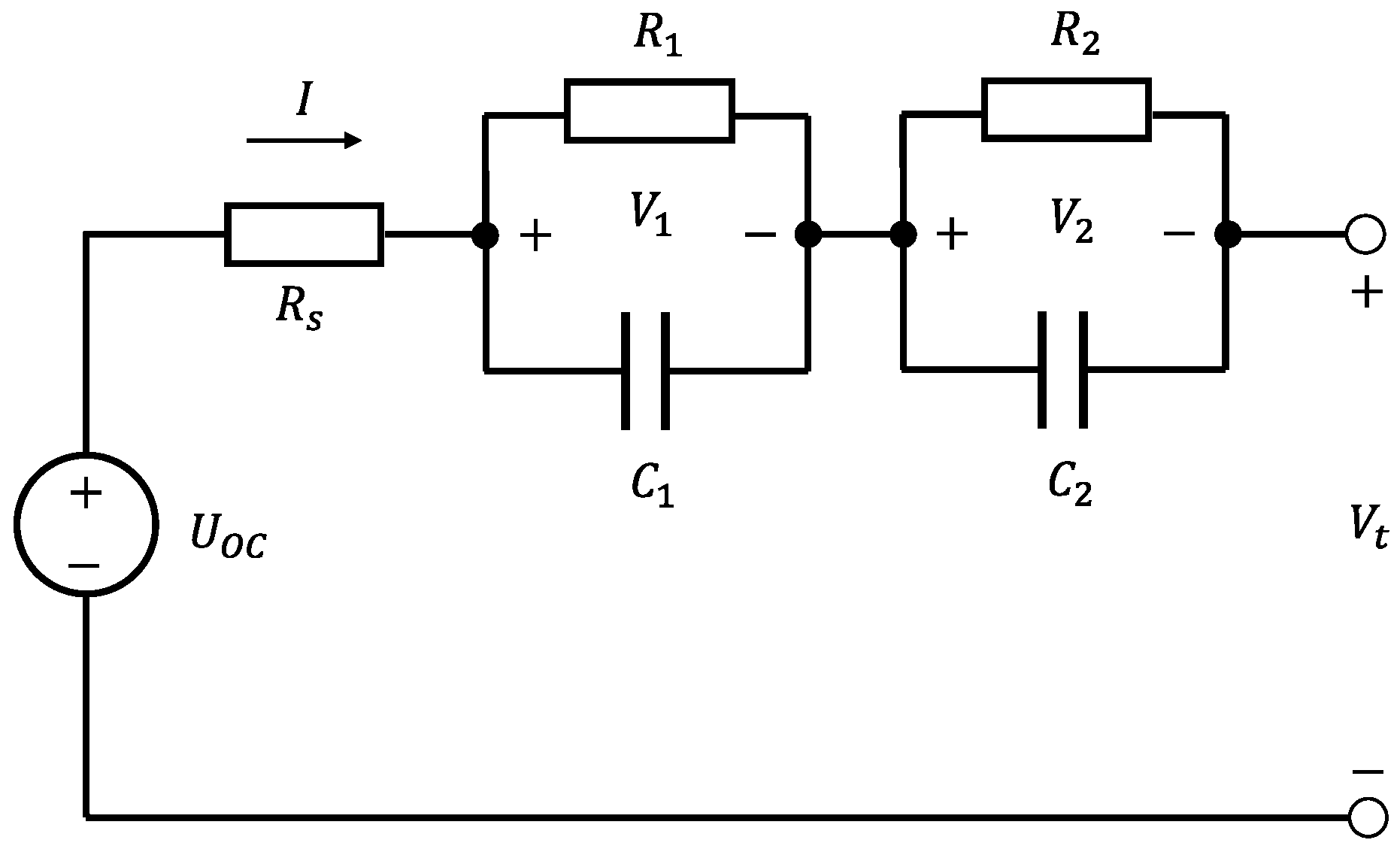
- A set of equivalent electrical circuit parameters for all four cell models tested at different temperatures.
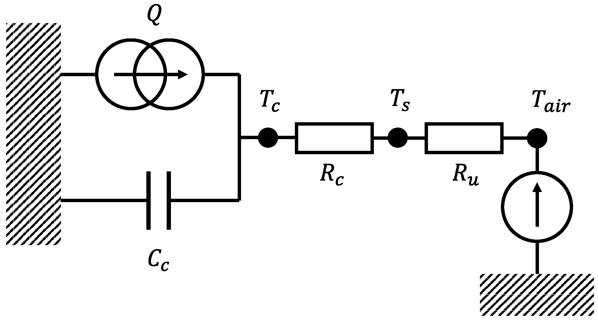
2. Reduced-Order Coupled Modeling of 18650 Cells
3. Testing and Characterization
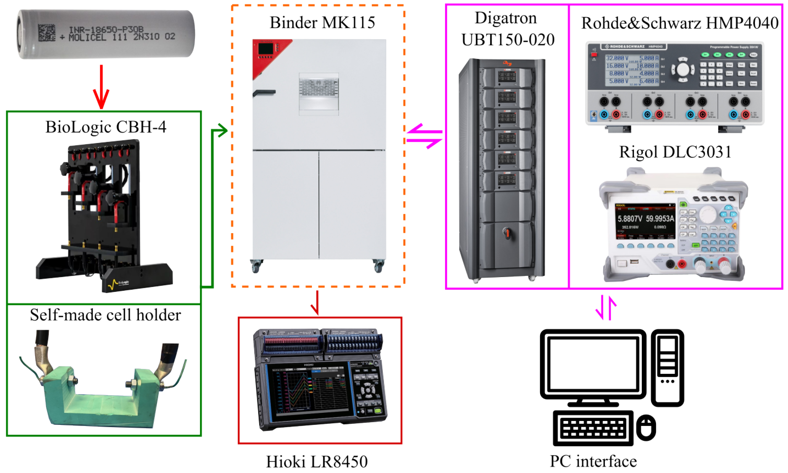
3.1. Materials and Experimental Set-Up
- A thermal chamber, Binder Mk115, to maintain a constant operating temperature in each experiment and to allow for testing at different temperatures;
- A four-terminal sensing cell holder, where a BioLogic CBH-4 was used for electrical tests;
- An in-house polymeric cell holder for thermal tests;
- A thermocouple array, to detect the battery surface temperature and the room temperature inside the thermal chamber, connected to a Hioki LR8450 data logger;
- A cell cycler consisting of a Rohde&Schwarz® (Munich, Germany) HMP4040 charger with a Rigol DLC3031 (Beijing, China) load to measure the entropic contribution and the pseudo- experiment, while for the other test a Digatron Systems UBT150-020 (Aachen, Germany) cells cycler was used.
3.2. Electrical Characterization Tests
3.2.1. Capacity Determination
- Fully charge the cell to with (a) 1 C constant current (CC) until the voltage reaches the upper cut-off ( ) and (b) constant voltage (CV) until the current decreases to the rate C/20, at the reference temperature = 25 °C.
- Set the thermal chamber to the temperature and wait 1 h to allow for cell temperature and voltage relaxation.
- Discharge the cell at CC with a rate until the voltage decreases to the lower cut-off voltage of .
- Bring the thermal chamber to the reference temperature and wait 1 h to allow for cell temperature and voltage relaxation.
- Repeat steps 1–4 five times.
3.2.2. OCV Measurements
- Fully charge the cell to with (a) 1 C CC until the voltage reaches the upper cut-off ( ) and (b) CV until the current decreases to a rate C/20, at the reference temperature = 25 °C.
- Relax the cell voltage for 1 h.
- Discharge the cell with CC at a rate C/20 until the voltage decreases to the lower cut-off of .
- Charge the cell with CC at a rate C/20 until the voltage reaches the upper cut-off of .
3.2.3. Gitt Characterization Tests
- Fully charge the cell () with (a) 1 C CC until the voltage reaches the upper cut-off ( ) and (b) CV until the current is reduced to a rate C/20, at the reference temperature = 25 °C.
- Relax the cell voltage for 1 h.
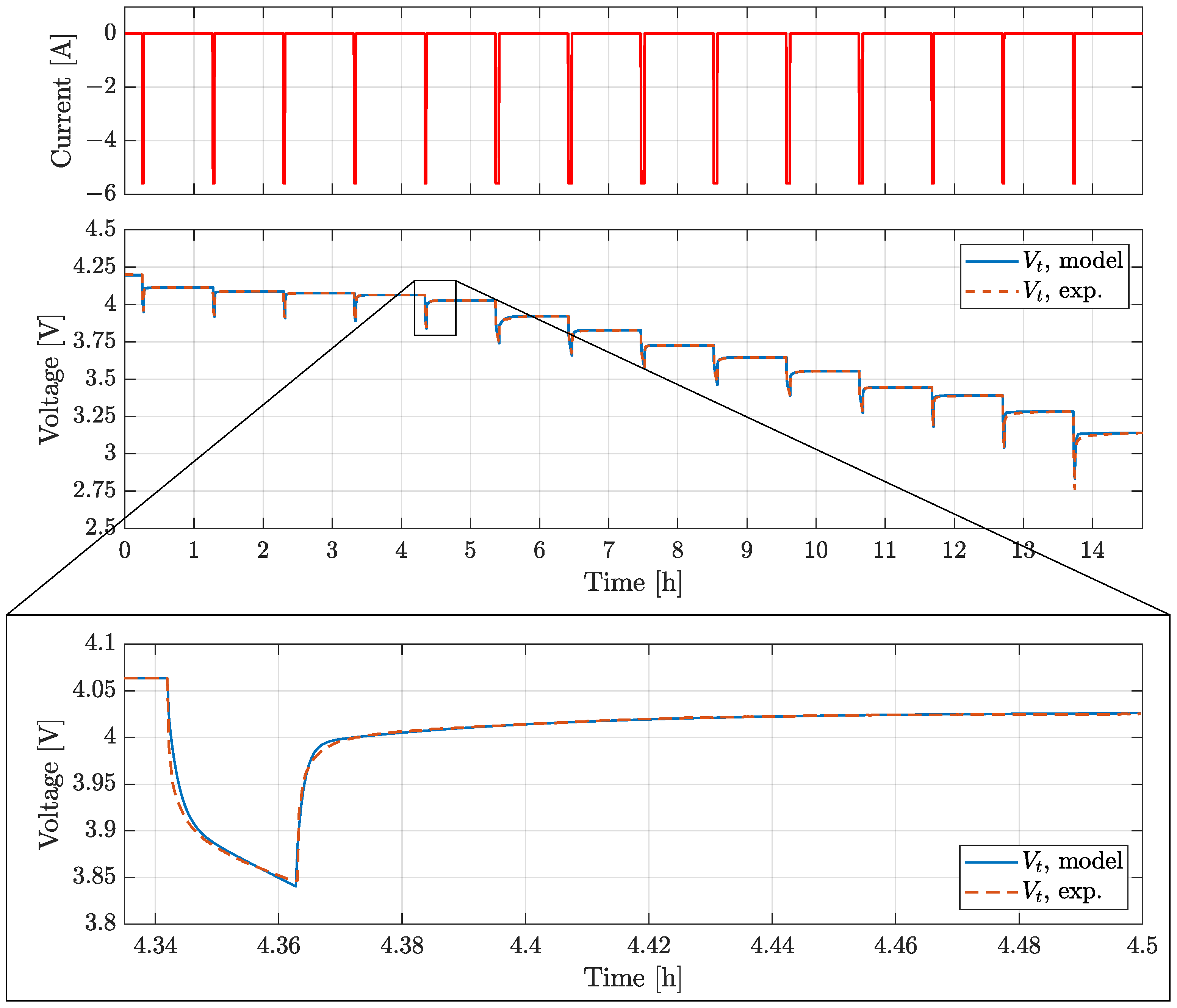
- Impose a discharge 2 C current impulse lasting for and then relax the battery voltage for 1 h.
- Repeat step 3 until the voltage reaches the lower cut-off of and then relax the battery voltage for 1 h.
- Repeat step 3 with a charge current impulse until the voltage reaches the upper cut-off of .
- Repeat the impulsive test at 5 °C and 40 °C.
3.3. Entropic Contribution Measurement
- Fully charge the cell to at the reference temperature = 25 °C.
- Relax the cell voltage for 20 h.
- Apply a controlled thermal cycle (1 h at 20 °C, 1 h at 10 °C, 1 h at 30 °C, 1 h at 40 °C, and 1 h at 25 °C).
- Discharge the cell for at a 1 C rate and then charge at a C rate for .
- Relax the cell voltage for 1 h.
- Repeat steps 3–5 until the voltage reaches the lower cut-off of .
3.4. Thermal Characterization Tests
- Fully charge the cell and then discharge to at the reference temperature = 25 °C.
- Relax the cell voltage and temperature for 1 h.
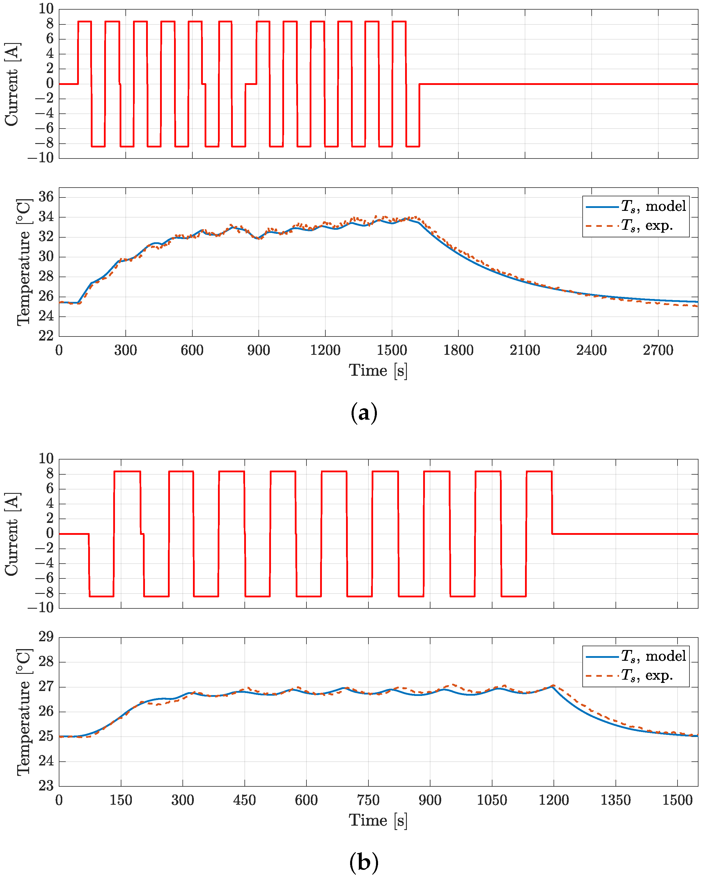
- Apply a square alternating wave load current with a period of 120 and a peak-to-peak amplitude corresponding to a rate of 6 C until a steady-state thermal equilibrium is reached on the cell surface. In this way, the entropic heat contribution could be neglected (see Equation (1)).
- Repeat steps 1–3 for two heat exchange conditions:() Low-convective heat transfer condition (the cell is placed in and exchanges heat by natural convection with the air inside the thermal chamber);() High-convective heat transfer condition (the cell is placed in and a pair of fans cools it down, so that heat exchange is mainly driven by forced convection).
4. Model Validation
5. Conclusions
Author Contributions
Funding
Data Availability Statement
Conflicts of Interest
Acronyms
| ARC | accelerating rate calorimeter |
| BJDST | Beijing Dynamic Stress Test |
| BMS | battery management system |
| CC | constant current |
| CPM | common potentiometric method |
| CV | constant voltage |
| ECM | equivalent circuit model |
| EIS | electrothermal impedance spectroscopy |
| FSAE | Formula of the Society of Automotive Engineers |
| FUDS | Federal Urban Driving Schedule |
| HPL | High-Power Load |
| NDC | Non-Dynamic Cycle |
| OCV | open-circuit voltage |
| PAM | positive adjustment Method |
| RMSE | root mean square Error |
| SoC | state of charge |
Appendix A
| Tc = 5 °C | |||||||||||
| Discharge | Charge | ||||||||||
| SoC | Rs | R1 | C1 | R2 | C2 | Rs | R1 | C1 | R2 | C2 | |
| [Ω] | [Ω] | [F] | [Ω] | [F] | [Ω] | [Ω] | [F] | [Ω] | [F] | ||
| 0.1 | 0.0271 | 0.0308 | 1173 | 0.0196 | 21,970 | 0.0266 | 0.0433 | 8526 | 0.0355 | 24,350 | |
| 0.2 | 0.0263 | 0.0219 | 1412 | 0.0211 | 33,364 | 0.0242 | 0.0662 | 4058 | 0.0281 | 21,050 | |
| 0.3 | 0.0264 | 0.0230 | 1573 | 0.0225 | 42,927 | 0.0222 | 0.0570 | 512 | 0.0155 | 20,215 | |
| 0.4 | 0.0269 | 0.0216 | 1197 | 0.0154 | 40,665 | 0.0218 | 0.0171 | 886 | 0.0268 | 16,880 | |
| 0.5 | 0.0272 | 0.0178 | 819 | 0.0130 | 33,119 | 0.0217 | 0.0132 | 823 | 0.0110 | 20,650 | |
| 0.6 | 0.0273 | 0.0152 | 646 | 0.0190 | 23,145 | 0.0208 | 0.0127 | 941 | 0.0092 | 21,596 | |
| 0.7 | 0.0283 | 0.0134 | 775 | 0.0325 | 15,821 | 0.0227 | 0.0148 | 1085 | 0.0135 | 31,539 | |
| 0.8 | 0.0305 | 0.0183 | 959 | 0.0397 | 11,399 | 0.0284 | 0.0114 | 1531 | 0.0140 | 34,055 | |
| 0.9 | 0.0313 | 0.0215 | 999 | 0.0180 | 24,522 | 0.0331 | 0.0059 | 2139 | 0.0096 | 22,909 | |
| Tc = 25 °C | |||||||||||
| Discharge | Charge | ||||||||||
| SoC | Rs | R1 | C1 | R2 | C2 | Rs | R1 | C1 | R2 | C2 | |
| [Ω] | [Ω] | [F] | [Ω] | [F] | [Ω] | [Ω] | [F] | [Ω] | [F] | ||
| 0.1 | 0.0191 | 0.0128 | 2345 | 0.0101 | 21,935 | 0.0166 | 0.0098 | 1141 | 0.0110 | 38,210 | |
| 0.2 | 0.0170 | 0.0083 | 1844 | 0.0080 | 19,192 | 0.0160 | 0.0092 | 2314 | 0.0109 | 53,291 | |
| 0.3 | 0.0165 | 0.0106 | 2187 | 0.0101 | 29,387 | 0.0155 | 0.0069 | 1735 | 0.0099 | 38,424 | |
| 0.4 | 0.0170 | 0.0106 | 1833 | 0.0069 | 36,820 | 0.0152 | 0.0068 | 1847 | 0.0068 | 34,442 | |
| 0.5 | 0.0173 | 0.0077 | 1408 | 0.0063 | 30,551 | 0.0152 | 0.0093 | 2521 | 0.0082 | 49,947 | |
| 0.6 | 0.0174 | 0.0073 | 1192 | 0.0121 | 35,108 | 0.0154 | 0.0084 | 2256 | 0.0075 | 45,617 | |
| 0.7 | 0.0173 | 0.0085 | 1375 | 0.0193 | 24,324 | 0.0155 | 0.0073 | 1505 | 0.0046 | 36,110 | |
| 0.8 | 0.0179 | 0.0106 | 1953 | 0.0125 | 19,786 | 0.0161 | 0.0110 | 1623 | 0.0052 | 43,433 | |
| 0.9 | 0.0184 | 0.0106 | 1874 | 0.0056 | 90,703 | 0.0148 | 0.0144 | 2441 | 0.0116 | 63,415 | |
| Tc = 40 °C | |||||||||||
| Discharge | Charge | ||||||||||
| SoC | Rs | R1 | C1 | R2 | C2 | Rs | R1 | C1 | R2 | C2 | |
| [Ω] | [Ω] | [F] | [Ω] | [F] | [Ω] | [Ω] | [F] | [Ω] | [F] | ||
| 0.1 | 0.0141 | 0.0169 | 2955 | 0.0086 | 162,380 | 0.0121 | 0.0088 | 1084 | 0.0203 | 40,517 | |
| 0.2 | 0.0132 | 0.0094 | 2871 | 0.0052 | 184,930 | 0.0134 | 0.0076 | 2574 | 0.0142 | 78,985 | |
| 0.3 | 0.0135 | 0.0092 | 3330 | 0.0045 | 178,230 | 0.0133 | 0.0044 | 1921 | 0.0121 | 34,480 | |
| 0.4 | 0.0137 | 0.0101 | 2264 | 0.0033 | 133,110 | 0.0132 | 0.0035 | 1918 | 0.0063 | 21,319 | |
| 0.5 | 0.0132 | 0.0082 | 1705 | 0.0031 | 90,442 | 0.0130 | 0.0046 | 2800 | 0.0059 | 24,030 | |
| 0.6 | 0.0130 | 0.0068 | 1995 | 0.0054 | 63,078 | 0.0131 | 0.0040 | 2360 | 0.0050 | 20,253 | |
| 0.7 | 0.0130 | 0.0094 | 2733 | 0.0079 | 48,266 | 0.0132 | 0.0033 | 2042 | 0.0038 | 17,394 | |
| 0.8 | 0.0142 | 0.0085 | 2367 | 0.0051 | 55,187 | 0.0135 | 0.0046 | 2425 | 0.0050 | 16,172 | |
| 0.9 | 0.0138 | 0.0074 | 1858 | 0.0044 | 104,600 | 0.0124 | 0.0063 | 2394 | 0.0096 | 15,963 | |
| Tc = 5 °C | |||||||||||
| Discharge | Charge | ||||||||||
| SoC | Rs | R1 | C1 | R2 | C2 | Rs | R1 | C1 | R2 | C2 | |
| [Ω] | [Ω] | [F] | [Ω] | [F] | [Ω] | [Ω] | [F] | [Ω] | [F] | ||
| 0.1 | 0.0307 | 0.0269 | 1037 | 0.0222 | 16,531 | 0.0312 | 0.0194 | 706 | 0.0409 | 16,162 | |
| 0.2 | 0.0273 | 0.0220 | 1333 | 0.0262 | 31,633 | 0.0290 | 0.0168 | 930 | 0.0295 | 15,259 | |
| 0.3 | 0.0271 | 0.0227 | 12,08 | 0.0227 | 33,162 | 0.0264 | 0.0139 | 931 | 0.0114 | 19,789 | |
| 0.4 | 0.0279 | 0.0197 | 915 | 0.0157 | 25,628 | 0.0235 | 0.0135 | 932 | 0.0114 | 19,789 | |
| 0.5 | 0.0276 | 0.0166 | 657 | 0.0136 | 17,738 | 0.0220 | 0.0185 | 921 | 0.0164 | 28,506 | |
| 0.6 | 0.0207 | 0.0143 | 581 | 0.0197 | 13,993 | 0.0206 | 0.0212 | 1121 | 0.0198 | 34,355 | |
| 0.7 | 0.0289 | 0.0137 | 744 | 0.0367 | 12,739 | 0.0192 | 0.0175 | 1338 | 0.0114 | 19,324 | |
| 0.8 | 0.0329 | 0.0214 | 911 | 0.0528 | 9585 | 0.0179 | 0.0190 | 1303 | 0.0150 | 17,600 | |
| 0.9 | 0.0345 | 0.0230 | 817 | 0.0334 | 14,201 | 0.0166 | 0.0185 | 1206 | 0.0160 | 21,537 | |
| Tc = 25 °C | |||||||||||
| Discharge | Charge | ||||||||||
| SoC | Rs | R1 | C1 | R2 | C2 | Rs | R1 | C1 | R2 | C2 | |
| [Ω] | [Ω] | [F] | [Ω] | [F] | [Ω] | [Ω] | [F] | [Ω] | [F] | ||
| 0.1 | 0.0178 | 0.0190 | 2365 | 0.0105 | 46,810 | 0.0161 | 0.0110 | 1094 | 0.0203 | 23,947 | |
| 0.2 | 0.0161 | 0.0102 | 1757 | 0.0078 | 27,662 | 0.0155 | 0.0113 | 2165 | 0.0185 | 44,449 | |
| 0.3 | 0.0159 | 0.0106 | 2445 | 0.0104 | 34,794 | 0.0147 | 0.0071 | 1525 | 0.0123 | 29,553 | |
| 0.4 | 0.0162 | 0.0112 | 1950 | 0.0071 | 42,074 | 0.0142 | 0.0065 | 1385 | 0.0077 | 25,390 | |
| 0.5 | 0.0163 | 0.0082 | 1328 | 0.0060 | 37,689 | 0.0139 | 0.0095 | 1699 | 0.0084 | 37,180 | |
| 0.6 | 0.0164 | 0.0083 | 1039 | 0.0115 | 35,216 | 0.0137 | 0.0099 | 1510 | 0.0085 | 37,336 | |
| 0.7 | 0.0171 | 0.0073 | 1779 | 0.0202 | 23,936 | 0.0138 | 0.0080 | 1058 | 0.0052 | 26,508 | |
| 0.8 | 0.0177 | 0.0135 | 1339 | 0.0146 | 16,296 | 0.0138 | 0.0118 | 1304 | 0.0061 | 33,520 | |
| 0.9 | 0.0181 | 0.0114 | 1615 | 0.0067 | 59,597 | 0.0158 | 0.0130 | 2103 | 0.0120 | 47,036 | |
| Tc = 40 °C | |||||||||||
| Discharge | Charge | ||||||||||
| SoC | Rs | R1 | C1 | R2 | C2 | Rs | R1 | C1 | R2 | C2 | |
| [Ω] | [Ω] | [F] | [Ω] | [F] | [Ω] | [Ω] | [F] | [Ω] | [F] | ||
| 0.1 | 0.0126 | 0.0161 | 2360 | 0.0084 | 142,620 | 0.0120 | 0.0091 | 1243 | 0.0143 | 32,013 | |
| 0.2 | 0.0111 | 0.0095 | 1792 | 0.0047 | 104,860 | 0.0116 | 0.0075 | 2534 | 0.0092 | 75,070 | |
| 0.3 | 0.0111 | 0.0086 | 2315 | 0.0046 | 71,871 | 0.0116 | 0.0055 | 2529 | 0.0112 | 59,639 | |
| 0.4 | 0.0119 | 0.0076 | 2389 | 0.0048 | 50,264 | 0.0112 | 0.0047 | 2021 | 0.0060 | 41,868 | |
| 0.5 | 0.0125 | 0.0052 | 1959 | 0.0050 | 43,107 | 0.0106 | 0.0068 | 2819 | 0.0047 | 53,780 | |
| 0.6 | 0.0125 | 0.0051 | 2382 | 0.0094 | 43,637 | 0.0100 | 0.0080 | 2985 | 0.0053 | 78,268 | |
| 0.7 | 0.0127 | 0.0083 | 3214 | 0.0138 | 38,551 | 0.0110 | 0.0062 | 1864 | 0.0033 | 111,810 | |
| 0.8 | 0.0130 | 0.0092 | 2863 | 0.0091 | 85,219 | 0.0114 | 0.0084 | 2512 | 0.0046 | 136,800 | |
| 0.9 | 0.0132 | 0.0071 | 2231 | 0.0056 | 93,891 | 0.0116 | 0.0116 | 2404 | 0.0073 | 74,297 | |
| Tc = 5 °C | |||||||||||
| Discharge | Charge | ||||||||||
| SoC | Rs | R1 | C1 | R2 | C2 | Rs | R1 | C1 | R2 | C2 | |
| [Ω] | [Ω] | [F] | [Ω] | [F] | [Ω] | [Ω] | [F] | [Ω] | [F] | ||
| 0.1 | 0.0238 | 0.0311 | 1356 | 0.0406 | 26,412 | 0.0228 | 0.0795 | 4076 | 0.0190 | 50,626 | |
| 0.2 | 0.0189 | 0.0218 | 1160 | 0.0231 | 26,096 | 0.0207 | 0.0606 | 4832 | 0.0319 | 60,550 | |
| 0.3 | 0.0176 | 0.0211 | 1146 | 0.0274 | 24,765 | 0.0174 | 0.0179 | 1907 | 0.0353 | 57,155 | |
| 0.4 | 0.0175 | 0.0211 | 1011 | 0.0295 | 23,330 | 0.0142 | 0.0116 | 1858 | 0.0184 | 29,798 | |
| 0.5 | 0.0177 | 0.0188 | 824 | 0.0202 | 15,980 | 0.0140 | 0.0134 | 1026 | 0.0110 | 19,511 | |
| 0.6 | 0.0180 | 0.0135 | 652 | 0.0200 | 10,938 | 0.0137 | 0.0158 | 831 | 0.0128 | 28,351 | |
| 0.7 | 0.0188 | 0.0147 | 742 | 0.0373 | 10,167 | 0.0135 | 0.0203 | 965 | 0.0170 | 38,968 | |
| 0.8 | 0.0213 | 0.0236 | 1197 | 0.0512 | 16,595 | 0.0137 | 0.0173 | 938 | 0.0089 | 34,889 | |
| 0.9 | 0.0224 | 0.0244 | 1100 | 0.0202 | 27,749 | 0.0145 | 0.0280 | 1012 | 0.0135 | 47,824 | |
| Tc = 25 °C | |||||||||||
| Discharge | Charge | ||||||||||
| SoC | Rs | R1 | C1 | R2 | C2 | Rs | R1 | C1 | R2 | C2 | |
| [Ω] | [Ω] | [F] | [Ω] | [F] | [Ω] | [Ω] | [F] | [Ω] | [F] | ||
| 0.1 | 0.0170 | 0.0394 | 1760 | 0.0255 | 49,984 | 0.0114 | 0.0345 | 2178 | 0.0144 | 62,725 | |
| 0.2 | 0.0118 | 0.0179 | 1731 | 0.0115 | 64,108 | 0.0106 | 0.0164 | 1909 | 0.0338 | 48,519 | |
| 0.3 | 0.0110 | 0.0130 | 1302 | 0.0083 | 43,164 | 0.0096 | 0.0064 | 1763 | 0.0209 | 23,110 | |
| 0.4 | 0.0105 | 0.0110 | 1239 | 0.0082 | 29,060 | 0.0094 | 0.0041 | 1100 | 0.0106 | 11,786 | |
| 0.5 | 0.0116 | 0.0108 | 1862 | 0.0090 | 19,562 | 0.0094 | 0.0046 | 1170 | 0.0078 | 11,054 | |
| 0.6 | 0.0119 | 0.0078 | 1297 | 0.0076 | 16,602 | 0.0093 | 0.0068 | 1062 | 0.0101 | 16,393 | |
| 0.7 | 0.0120 | 0.0086 | 1273 | 0.0138 | 26,587 | 0.0095 | 0.0060 | 1109 | 0.0087 | 14,093 | |
| 0.8 | 0.0127 | 0.0128 | 2017 | 0.0168 | 21,666 | 0.0096 | 0.0054 | 1227 | 0.0075 | 7982 | |
| 0.9 | 0.0127 | 0.0125 | 1652 | 0.0069 | 95,862 | 0.0103 | 0.0088 | 1371 | 0.0132 | 10,814 | |
| Tc = 40 °C | |||||||||||
| Discharge | Charge | ||||||||||
| SoC | Rs | R1 | C1 | R2 | C2 | Rs | R1 | C1 | R2 | C2 | |
| [Ω] | [Ω] | [F] | [Ω] | [F] | [Ω] | [Ω] | [F] | [Ω] | [F] | ||
| 0.1 | 0.0110 | 0.0274 | 6336 | 0.0309 | 57,321 | 0.0090 | 0.0160 | 1332 | 0.0651 | 14,153 | |
| 0.2 | 0.0093 | 0.0131 | 3732 | 0.0141 | 105,080 | 0.0081 | 0.0077 | 1708 | 0.0662 | 14,516 | |
| 0.3 | 0.0087 | 0.0103 | 2516 | 0.0095 | 124,580 | 0.0076 | 0.0037 | 1253 | 0.0245 | 26,619 | |
| 0.4 | 0.0080 | 0.0083 | 1943 | 0.0064 | 130,980 | 0.0076 | 0.0045 | 900 | 0.0125 | 39,521 | |
| 0.5 | 0.0084 | 0.0095 | 2198 | 0.0043 | 90,444 | 0.0076 | 0.0061 | 1006 | 0.0115 | 58,670 | |
| 0.6 | 0.0092 | 0.0068 | 2204 | 0.0066 | 75,590 | 0.0077 | 0.0070 | 1493 | 0.0081 | 37,061 | |
| 0.7 | 0.0093 | 0.0070 | 2610 | 0.0066 | 78,856 | 0.0078 | 0.0054 | 1540 | 0.0081 | 37,061 | |
| 0.8 | 0.0095 | 0.0102 | 3046 | 0.0073 | 75,567 | 0.0080 | 0.0045 | 1549 | 0.0053 | 36,016 | |
| 0.9 | 0.0095 | 0.0077 | 2187 | 0.0054 | 129,950 | 0.0083 | 0.0083 | 2227 | 0.0081 | 50,669 | |
| Tc = 5 °C | |||||||||||
| Discharge | Charge | ||||||||||
| SoC | Rs | R1 | C1 | R2 | C2 | Rs | R1 | C1 | R2 | C2 | |
| [Ω] | [Ω] | [F] | [Ω] | [F] | [Ω] | [Ω] | [F] | [Ω] | [F] | ||
| 0.1 | 0.0265 | 0.0330 | 1125 | 0.0271 | 11,198 | 0.0291 | 0.0219 | 658 | 0.0450 | 8029 | |
| 0.2 | 0.0249 | 0.0188 | 1367 | 0.0154 | 15,964 | 0.0266 | 0.0067 | 768 | 0.0324 | 3196 | |
| 0.3 | 0.0238 | 0.0215 | 1650 | 0.0197 | 25,405 | 0.0232 | 0.0073 | 804 | 0.0168 | 5071 | |
| 0.4 | 0.0235 | 0.0243 | 1814 | 0.0218 | 31,775 | 0.0216 | 0.0066 | 1080 | 0.0144 | 5541 | |
| 0.5 | 0.0238 | 0.0206 | 1440 | 0.0149 | 30,667 | 0.0216 | 0.0096 | 962 | 0.0211 | 6901 | |
| 0.6 | 0.0243 | 0.0173 | 1222 | 0.0151 | 30,607 | 0.0218 | 0.0117 | 647 | 0.0214 | 7393 | |
| 0.7 | 0.0254 | 0.0159 | 1552 | 0.0287 | 26,171 | 0.0227 | 0.0121 | 818 | 0.0128 | 6113 | |
| 0.8 | 0.0273 | 0.0259 | 1767 | 0.0387 | 20,423 | 0.0264 | 0.0160 | 1208 | 0.0145 | 8581 | |
| 0.9 | 0.0294 | 0.0259 | 1251 | 0.0154 | 34,463 | 0.0402 | 0.0245 | 2300 | 0.0450 | 17,704 | |
| Tc = 25 °C | |||||||||||
| Discharge | Charge | ||||||||||
| SoC | Rs | R1 | C1 | R2 | C2 | Rs | R1 | C1 | R2 | C2 | |
| [Ω] | [Ω] | [F] | [Ω] | [F] | [Ω] | [Ω] | [F] | [Ω] | [F] | ||
| 0.1 | 0.0227 | 0.0165 | 2772 | 0.0123 | 15,823 | 0.0163 | 0.0358 | 2089 | 0.0175 | 62,603 | |
| 0.2 | 0.0176 | 0.0089 | 1832 | 0.0066 | 19,355 | 0.0154 | 0.0133 | 2257 | 0.0234 | 51,085 | |
| 0.3 | 0.0158 | 0.0105 | 1741 | 0.0078 | 17,670 | 0.0147 | 0.0106 | 1727 | 0.0230 | 24,814 | |
| 0.4 | 0.0151 | 0.0123 | 1760 | 0.0092 | 17,286 | 0.0144 | 0.0070 | 1581 | 0.0118 | 15,220 | |
| 0.5 | 0.0156 | 0.0086 | 1208 | 0.0097 | 13,320 | 0.0144 | 0.0082 | 1632 | 0.0103 | 16,589 | |
| 0.6 | 0.0160 | 0.0079 | 1198 | 0.0186 | 17,363 | 0.0146 | 0.0084 | 1337 | 0.0094 | 16,235 | |
| 0.7 | 0.0160 | 0.0114 | 1898 | 0.0259 | 24,139 | 0.0150 | 0.0080 | 1328 | 0.0057 | 14,737 | |
| 0.8 | 0.0167 | 0.0146 | 2295 | 0.0157 | 18,389 | 0.0158 | 0.0115 | 1324 | 0.0058 | 21,896 | |
| 0.9 | 0.0174 | 0.0127 | 1965 | 0.0061 | 37,337 | 0.0137 | 0.0197 | 1617 | 0.0121 | 41,477 | |
| Tc = 40 °C | |||||||||||
| Discharge | Charge | ||||||||||
| SoC | Rs | R1 | C1 | R2 | C2 | Rs | R1 | C1 | R2 | C2 | |
| [Ω] | [Ω] | [F] | [Ω] | [F] | [Ω] | [Ω] | [F] | [Ω] | [F] | ||
| 0.1 | 0.0150 | 0.0184 | 2727 | 0.0086 | 80,205 | 0.0116 | 0.0193 | 1153 | 0.0372 | 18,047 | |
| 0.2 | 0.0138 | 0.0093 | 2013 | 0.0043 | 44,757 | 0.0117 | 0.0099 | 1311 | 0.0184 | 40,515 | |
| 0.3 | 0.0127 | 0.0083 | 1614 | 0.0041 | 30,351 | 0.0120 | 0.0078 | 1806 | 0.0160 | 55,242 | |
| 0.4 | 0.0124 | 0.0089 | 1788 | 0.0060 | 20,576 | 0.0123 | 0.0069 | 1619 | 0.0083 | 45,626 | |
| 0.5 | 0.0133 | 0.0063 | 1975 | 0.0066 | 16,017 | 0.0122 | 0.0084 | 1929 | 0.0078 | 38,101 | |
| 0.6 | 0.0133 | 0.0057 | 2361 | 0.0062 | 21,600 | 0.0123 | 0.0068 | 1826 | 0.0065 | 32,643 | |
| 0.7 | 0.0134 | 0.0090 | 3291 | 0.0090 | 31,691 | 0.0127 | 0.0060 | 1701 | 0.0040 | 34,223 | |
| 0.8 | 0.0137 | 0.0096 | 2348 | 0.0056 | 21,288 | 0.0131 | 0.0083 | 1671 | 0.0044 | 39,989 | |
| 0.9 | 0.0141 | 0.0058 | 2081 | 0.0039 | 10,820 | 0.0116 | 0.0142 | 1904 | 0.0087 | 61,896 | |
References
- Bashir, T.; Ismail, S.A.; Song, Y.; Irfan, R.M.; Yang, S.; Zhou, S.; Zhaou, J.; Gao, L. A review of the energy storage aspects of chemical elements for lithium-ion based batteries. Energy Mater. 2021, 1, 100019. [Google Scholar] [CrossRef]
- Kumar, R.; Goel, V. A study on thermal management system of lithium-ion batteries for electrical vehicles: A critical review. J. Energy Storage 2023, 71, 108025. [Google Scholar] [CrossRef]
- Abdalla, A.M.; Abdullah, M.F.; Dawood, M.K.; Wei, B.; Subramanian, Y.; Azad, A.T.; Nourin, S.; Afroze, S.; Taweekun, J.; Azad, A.K. Innovative lithium-ion battery recycling: Sustainable process for recovery of critical materials from lithium-ion batteries. J. Energy Storage 2023, 67, 107551. [Google Scholar] [CrossRef]
- Wu, F.; Maier, J.; Yu, Y. Guidelines and trends for next-generation rechargeable lithium and lithium-ion batteries. Chem. Soc. Rev. 2020, 49, 1569–1614. [Google Scholar] [CrossRef] [PubMed]
- Zhou, C.; Dong, C.; Wang, W.; Tian, Y.; Shen, C.; Yan, K.; Mai, L.; Xu, X. An ultrathin and crack-free metal-organic framework film for effective polysulfide inhibition in lithium–sulfur batteries. Interdiscip. Mater. 2024, 3, 306–315. [Google Scholar] [CrossRef]
- Dong, C.; Zhou, C.; Wu, M.; Yu, Y.; Yu, K.; Yan, K.; Shen, C.; Gu, J.; Yan, M.; Sun, C.; et al. Boosting Bi-Directional Redox of Sulfur with Dual Metal Single Atom Pairs in Carbon Spheres Toward High-Rate and Long-Cycling Lithium–Sulfur Battery. Adv. Energy Mater. 2023, 13, 2301505. [Google Scholar] [CrossRef]
- Jaguemont, J.; Boulon, L.; Dubé, Y. A comprehensive review of lithium-ion batteries used in hybrid and electric vehicles at cold temperatures. Appl. Energy 2016, 164, 99–114. [Google Scholar] [CrossRef]
- Zhou, W.; Liu, Z.; Chen, W.; Sun, X.; Luo, M.; Zhang, X.; Li, C.; An, Y.; Song, S.; Wang, K.; et al. A Review on Thermal Behaviors and Thermal Management Systems for Supercapacitors. Batteries 2023, 9, 128. [Google Scholar] [CrossRef]
- Trovò, A.; Guarnieri, M. Battery management system with testing protocols for kW-class vanadium redox flow batteries. In Proceedings of the 2020 2nd IEEE International Conference on Industrial Electronics for Sustainable Energy Systems (IESES), Online, 20–22 April 2020; Volume 1, pp. 33–38. [Google Scholar] [CrossRef]
- Zatta, N.; Bonanno, G.; Trovò, A.; Visonà, S.; Cristofoli, G.; Mozzato, L.; Mattavelli, P.; Guarnieri, M. A Thermal Investigation on a Commercial Stack of Prismatic Lithium-Ion Batteries. In Proceedings of the 2023 IEEE International Conference on Electrical Systems for Aircraft, Railway, Ship Propulsion and Road Vehicles and International Transportation Electrification Conference (ESARS-ITEC), Venice, Italy, 29–31 March 2023; Available online: https://ieeexplore.ieee.org/document/10114827 (accessed on 20 June 2024).
- Lin, Z.; Wu, D.; Du, C.; Ren, Z. An improved potentiometric method for the measurement of entropy coefficient of lithium-ion battery based on positive adjustment. Energy Rep. 2022, 8, 54–63. [Google Scholar] [CrossRef]
- Adaikkappan, M.; Sathiyamoorthy, N. Modeling, state of charge estimation, and charging of lithium-ion battery in electric vehicle: A review. Int. J. Energy Res. 2022, 46, 2141–2165. [Google Scholar] [CrossRef]
- Barcellona, S.; Piegari, L. Lithium Ion Battery Models and Parameter Identification Techniques. Energies 2017, 10, 2007. [Google Scholar] [CrossRef]
- Geng, Z.; Wang, S.; Lacey, M.J.; Brandell, D.; Thiringer, T. Bridging physics-based and equivalent circuit models for lithium-ion batteries. Electrochim. Acta 2021, 372, 137829. [Google Scholar] [CrossRef]
- Liang, Y.; Emadi, A.; Gross, O.; Vidal, C.; Canova, M.; Panchal, S.; Kollmeyer, P.J.; Naguib, M.; Khanum, F. A Comparative Study between Physics, Electrical and Data Driven Lithium-Ion Battery Voltage Modeling Approaches; SAE Technical Paper Series; SAE International: Warrendale PA, USA, 2022. [Google Scholar]
- Ekström, H.; Fridholm, B.; Lindbergh, G. Comparison of lumped diffusion models for voltage prediction of a lithium-ion battery cell during dynamic loads. J. Power Sources 2018, 402, 296–300. [Google Scholar] [CrossRef]
- Jackey, R.; Saginaw, M.; Sanghvi, P.; Gazzarri, J.; Huria, T.; Ceraolo, M. Battery Model Parameter Estimation Using a Layered Technique: An Example Using a Lithium Iron Phosphate Cell; SAE Technical Paper; SAE International: Warrendale PA, USA, 2013; Volume 1547. [Google Scholar] [CrossRef]
- Akbarzadeh, M.; Kalogiannis, T.; Jaguemont, J.; He, J.; Jin, L.; Berecibar, M.; Van Mierlo, J. Thermal modeling of a high-energy prismatic lithium-ion battery cell and module based on a new thermal characterization methodology. J. Energy Storage 2020, 32, 101707. [Google Scholar] [CrossRef]
- Tran, M.K.; DaCosta, A.; Mevawalla, A.; Panchal, S.; Fowler, M. Comparative Study of Equivalent Circuit Models Performance in Four Common Lithium-Ion Batteries: LFP, NMC, LMO, NCA. Batteries 2021, 7, 51. [Google Scholar] [CrossRef]
- Hua, X.; Zhang, C.; Offer, G. Finding a better fit for lithium ion batteries: A simple, novel, load dependent, modified equivalent circuit model and parameterization method. J. Power Sources 2021, 484, 229117. [Google Scholar] [CrossRef]
- Lin, X.; Perez, H.E.; Mohan, S.; Siegel, J.B.; Stefanopoulou, A.G.; Ding, Y.; Castanier, M.P. A lumped-parameter electro-thermal model for cylindrical batteries. J. Power Sources 2014, 257, 1–11. [Google Scholar] [CrossRef]
- Madani, S.S.; Schaltz, E.; Knudsen Kær, S. Review of Parameter Determination for Thermal Modeling of Lithium Ion Batteries. Batteries 2018, 4, 20. [Google Scholar] [CrossRef]
- Chin, C.; Gao, Z.; Zhang, C. Comprehensive electro-thermal model of 26650 lithium battery for discharge cycle under parametric and temperature variations. J. Energy Storage 2020, 28, 101222. [Google Scholar] [CrossRef]
- Forgez, C.; Vinh Do, D.; Friedrich, G.; Morcrette, M.; Delacourt, C. Thermal modeling of a cylindrical LiFePO4/graphite lithium-ion battery. J. Power Sources 2010, 195, 2961–2968. [Google Scholar] [CrossRef]
- Asus, Z.; Aglzim, E.H.; Chrenko, D.; Daud, Z.H.C.; Le Moyne, L. Dynamic Modeling and Driving Cycle Prediction for a Racing Series Hybrid Car. IEEE J. Emerg. Sel. Top. Power Electron. 2014, 2, 541–551. [Google Scholar] [CrossRef]
- Mattarelli, E.; Rinaldini, C.A.; Scrignoli, F.; Mangeruga, V. Development of a Hybrid Power Unit for Formula SAE Application: ICE CFD-1D Optimization and Vehicle Lap Simulation. In Proceedings of the 14th International Conference on Engines & Vehicles, SAE International, Napoli, Italy, 15–19 September 2019. [Google Scholar] [CrossRef]
- Hutcheson, R.S.; McAdams, D.A. Conceptual Design of a Formula Hybrid Powertrain System Utilizing Functionality-Based Modeling Tools. In Proceedings of the 22nd International Conference on Design Theory and Methodology, Special Conference on Mechanical Vibration and Noise, International Design Engineering Technical Conferences and Computers and Information in Engineering Conference, Montreal, QC, Canada, 15–18 August 2010; Volume 5. [Google Scholar] [CrossRef]
- Muenzel, V.; Hollenkamp, A.F.; Bhatt, A.I.; de Hoog, J.; Brazil, M.; Thomas, D.A.; Mareels, I. A Comparative Testing Study of Commercial 18650-Format Lithium-Ion Battery Cells. J. Electrochem. Soc. 2015, 162, A1592. [Google Scholar] [CrossRef]
- Braco, E.; San Martín, I.; Berrueta, A.; Sanchis, P.; Ursúa, A. Experimental assessment of cycling ageing of lithium-ion second-life batteries from electric vehicles. J. Energy Storage 2020, 32, 101695. [Google Scholar] [CrossRef]
- Waldmann, T.; Scurtu, R.G.; Richter, K.; Wohlfahrt-Mehrens, M. 18650 vs. 21700 Li-ion cells—A direct comparison of electrochemical, thermal, and geometrical properties. J. Power Sources 2020, 472, 228614. [Google Scholar] [CrossRef]
- Mulpuri, S.K.; Sah, B.; Kumar, P. Protocol for conducting advanced cyclic tests in lithium-ion batteries to estimate capacity fade. STAR Protoc. 2024, 5, 102938. [Google Scholar] [CrossRef]
- Baumhöfer, T.; Brühl, M.; Rothgang, S.; Sauer, D.U. Production caused variation in capacity aging trend and correlation to initial cell performance. J. Power Sources 2014, 247, 332–338. [Google Scholar] [CrossRef]
- Soto, A.; Berrueta, A.; Sanchis, P.; Ursúa, A. Analysis of the main battery characterization techniques and experimental comparison of commercial 18650 Li-ion cells. In Proceedings of the 2019 IEEE International Conference on Environment and Electrical Engineering and 2019 IEEE Industrial and Commercial Power Systems Europe (EEEIC/I & CPS Europe), Genova, Italy, 11–14 June 2019; pp. 1–6. [Google Scholar] [CrossRef]
- Ren, Z.; Du, C.; Wu, Z.; Shao, J.; Deng, W. A comparative study of the influence of different open circuit voltage tests on model-based state of charge estimation for lithium-ion batteries. Int. J. Energy Res. 2021, 45, 13692–13711. [Google Scholar] [CrossRef]
- Pillai, P.; Sundaresan, S.; Kumar, P.; Pattipati, K.R.; Balasingam, B. Open-Circuit Voltage Models for Battery Management Systems: A Review. Energies 2022, 15, 6803. [Google Scholar] [CrossRef]
- Pillai, P.; Nguyen, J.; Balasingam, B. Performance Analysis of Empirical Open-Circuit Voltage Modeling in Lithium-ion Batteries, Part-2: Data Collection Procedure. IEEE Trans. Transp. Electrif. 2024. [Google Scholar] [CrossRef]
- Baronti, F.; Zamboni, W.; Roncella, R.; Saletti, R.; Spagnuolo, G. Open-circuit voltage measurement of Lithium-Iron-Phosphate batteries. In Proceedings of the 2015 IEEE International Instrumentation and Measurement Technology Conference (I2MTC) Proceedings, Pisa, Italy, 11–14 May 2015; pp. 1711–1716. [Google Scholar] [CrossRef]
- Pan, H.; Lü, Z.; Lin, W.; Li, J.; Chen, L. State of charge estimation of lithium-ion batteries using a grey extended Kalman filter and a novel open-circuit voltage model. Energy 2017, 138, 764–775. [Google Scholar] [CrossRef]
- Samieian, M.A.; Hales, A.; Patel, Y. A Novel Experimental Technique for Use in Fast Parameterisation of Equivalent Circuit Models for Lithium-Ion Batteries. Batteries 2022, 8, 125. [Google Scholar] [CrossRef]
- Zhang, X.F.; Zhao, Y.; Patel, Y.; Zhang, T.; Liu, W.M.; Chen, M.; Offer, G.J.; Yan, Y. Potentiometric measurement of entropy change for lithium batteries. Phys. Chem. Chem. Phys. 2017, 19, 9833–9842. [Google Scholar] [CrossRef] [PubMed]
- Eddahech, A.; Briat, O.; Vinassa, J.M. Thermal characterization of a high-power lithium-ion battery: Potentiometric and calorimetric measurement of entropy changes. Energy 2013, 61, 432–439. [Google Scholar] [CrossRef]
- Geng, Z.; Groot, J.; Thiringer, T. A Time- and Cost-Effective Method for Entropic Coefficient Determination of a Large Commercial Battery Cell. IEEE Trans. Transp. Electrif. 2020, 6, 257–266. [Google Scholar] [CrossRef]
- Xiao, M.; Choe, S.Y. Theoretical and experimental analysis of heat generations of a pouch type LiMn2O4/carbon high power Li-polymer battery. J. Power Sources 2013, 241, 46–55. [Google Scholar] [CrossRef]
- Damay, N.; Forgez, C.; Bichat, M.P.; Friedrich, G. A method for the fast estimation of a battery entropy-variation high-resolution curve—Application on a commercial LiFePO4/graphite cell. J. Power Sources 2016, 332, 149–153. [Google Scholar] [CrossRef]
- Schmidt, J.P.; Weber, A.; Ivers-Tiffée, E. A novel and precise measuring method for the entropy of lithium-ion cells: ΔS via electrothermal impedance spectroscopy. Electrochim. Acta 2014, 137, 311–319. [Google Scholar] [CrossRef]
- Hudak, N.S.; Davis, L.E.; Nagasubramanian, G. Cycling-Induced Changes in the Entropy Profiles of Lithium Cobalt Oxide Electrodes. J. Electrochem. Soc. 2014, 162, A315. [Google Scholar] [CrossRef]
- Zhao, W.; Rohde, M.; Mohsin, I.U.; Ziebert, C.; Seifert, H.J. Heat Generation in NMC622 Coin Cells during Electrochemical Cycling: Separation of Reversible and Irreversible Heat Effects. Batteries 2020, 6, 55. [Google Scholar] [CrossRef]
- Vertiz, G.; Oyarbide, M.; Macicior, H.; Miguel, O.; Cantero, I.; Fernandez de Arroiabe, P.; Ulacia, I. Thermal characterization of large size lithium-ion pouch cell based on 1d electro-thermal model. J. Power Sources 2014, 272, 476–484. [Google Scholar] [CrossRef]
- Sheng, L.; Su, L.; Zhang, H. Experimental determination on thermal parameters of prismatic lithium ion battery cells. Int. J. Heat Mass Transf. 2019, 139, 231–239. [Google Scholar] [CrossRef]
- Cao, R.; Zhang, X.; Yang, H.; Wang, C. Experimental study on heat generation characteristics of lithium-ion batteries using a forced convection calorimetry method. Appl. Therm. Eng. 2023, 219, 119559. [Google Scholar] [CrossRef]
- Tahir, M.W.; Merten, C. Multi-scale thermal modeling, experimental validation, and thermal characterization of a high-power lithium-ion cell for automobile application. Energy Convers. Manag. 2022, 258, 115490. [Google Scholar] [CrossRef]
- Jiaqiang, E.; Yue, M.; Chen, J.; Zhu, H.; Deng, Y.; Zhu, Y.; Zhang, F.; Wen, M.; Zhang, B.; Kang, S. Effects of the different air cooling strategies on cooling performance of a lithium-ion battery module with baffle. Appl. Therm. Eng. 2018, 144, 231–241. [Google Scholar] [CrossRef]
- Nie, P.; Zhang, S.W.; Ran, A.; Yang, C.; Chen, S.; Li, Z.; Zhang, X.; Deng, W.; Liu, T.; Kang, F.; et al. Full-cycle electrochemical-thermal coupling analysis for commercial lithium-ion batteries. Appl. Therm. Eng. 2021, 184, 116258. [Google Scholar] [CrossRef]
- Al-Zareer, M.; Ebbs-Picken, T.; Michalak, A.; Escobar, C.; Da Silva, C.M.; Davis, T.; Osio, I.; Amon, C.H. Heat generation rates and anisotropic thermophysical properties of cylindrical lithium-ion battery cells with different terminal mounting configurations. Appl. Therm. Eng. 2023, 223, 119990. [Google Scholar] [CrossRef]
- Samad, N.A.; Wang, B.; Siegel, J.B.; Stefanopoulou, A.G. Parameterization of Battery Electrothermal Models Coupled with Finite Element Flow Models for Cooling. J. Dyn. Syst. Meas. Control 2017, 139, 071003. [Google Scholar] [CrossRef]
- Lin, X.; Perez, H.E.; Siegel, J.B.; Stefanopoulou, A.G.; Li, Y.; Anderson, R.D.; Ding, Y.; Castanier, M.P. Online Parameterization of Lumped Thermal Dynamics in Cylindrical Lithium Ion Batteries for Core Temperature Estimation and Health Monitoring. IEEE Trans. Control Syst. Technol. 2013, 21, 1745–1755. [Google Scholar] [CrossRef]
- Farag, M.; Sweity, H.; Fleckenstein, M.; Habibi, S. Combined electrochemical, heat generation, and thermal model for large prismatic lithium-ion batteries in real-time applications. J. Power Sources 2017, 360, 618–633. [Google Scholar] [CrossRef]
- Bryden, T.S.; Dimitrov, B.; Hilton, G.; Ponce de León, C.; Bugryniec, P.; Brown, S.; Cumming, D.; Cruden, A. Methodology to determine the heat capacity of lithium-ion cells. J. Power Sources 2018, 395, 369–378. [Google Scholar] [CrossRef]
- Battery Data: Center for Advanced Life Cycle Engingeering (CALCE), University of Maryland. 2016. Available online: https://calce.umd.edu/battery-data#Storage (accessed on 1 February 2024).






| P28A | P28B | P30B | VTC5D | |
|---|---|---|---|---|
| Nominal capacity [mAh] | 2800 | 2800 | 3000 | 2800 |
| Minimum capacity [mAh] | 2600 | 2650 | 2900 | 2500 |
| Upper cut-off voltage [V] | 4.2 | |||
| Lower cut-off voltage [V] | 2.5 | |||
| Max. continuous discharge current [A] | 35 | 40 | 30 | 30 |
| Discharge temperature range [°C] | −40/+60 | −40/+60 | −40/+60 | −20/+60 |
| Internal resistance [mΩ] | 20 | 21 | 17 | n.r. |
| Size [mm] | ⌀ ≈ 18.6, h ≈ 65.2 | |||
| Mass [g] | 46 | 48 | 47 | 44 |
| Temperature | 0.5 C | 1 C | 3 C | 5 C | |
|---|---|---|---|---|---|
| [°C] | [mAh] | [mAh] | [mAh] | [mAh] | |
| P28A | 5 | 2656 ± 20 | 2575 ± 10 | 2541 ± 10 | 2562 ± 10 |
| 25 | 2747 ± 60 | 2685 ± 70 | 2620 ± 70 | 2606 ± 70 | |
| 40 | 2687 ± 30 | 2658 ± 20 | 2575 ± 20 | 2561 ± 30 | |
| P28B | 5 | 2527 ± 30 | 2490 ± 20 | 2459 ± 10 | 2477 ± 20 |
| 25 | 2720 ± 100 | 2670 ± 100 | 2581 ± 60 | 2567 ± 60 | |
| 40 | 2542 ± 30 | 2547 ± 20 | 2499 ± 30 | 2504 ± 80 | |
| P30B | 5 | 2825 ± 60 | 2747 ± 40 | 2710 ± 30 | 2810 ± 20 |
| 25 | 3041 ± 30 | 2943 ± 10 | 2915 ± 20 | 2908 ± 30 | |
| 40 | 3015 ± 40 | 2961 ± 20 | 2890 ± 10 | 2893 ± 10 | |
| VTC5D | 5 | 2712 ± 50 | 2616 ± 20 | 2568 ± 50 | 2578 ± 50 |
| 25 | 2861 ± 20 | 2791 ± 5 | 2685 ± 20 | 2668 ± 10 | |
| 40 | 2749 ± 50 | 2704 ± 40 | 2618 ± 60 | 2607 ± 40 |
| Cc | Rc | Ru1 | Ru2 | |
|---|---|---|---|---|
| [J/K] | [K/W] | [K/W] | [K/W] | |
| P28A | 56.3 | 0.41 | 6.02 | 1.07 |
| P28B | 55.7 | 0.24 | 5.54 | 2.49 |
| P30B | 70.2 | 0.10 | 4.94 | 0.80 |
| VTC5D | 68.6 | 0.15 | 5.54 | 1.90 |
| BJDST | FUDS | NDC | HPL | ||
|---|---|---|---|---|---|
| RMSE, Vt | RMSE, Vt | RMSE, Vt | RMSE, Vt | RMSE, Ts | |
| [mV] | [mV] | [mV] | [mV] | [°C] | |
| P28A | 4.4 | 7.3 | 17.7 | 15.4 | 0.21 |
| P28B | 5.7 | 14.7 | 12.9 | 16.5 | 0.30 |
| P30B | 9.8 | 12.1 | 17.7 | 17.8 | 0.20 |
| VTC5D | 5.3 | 8.8 | 13.6 | 15.9 | 0.25 |
Disclaimer/Publisher’s Note: The statements, opinions and data contained in all publications are solely those of the individual author(s) and contributor(s) and not of MDPI and/or the editor(s). MDPI and/or the editor(s) disclaim responsibility for any injury to people or property resulting from any ideas, methods, instructions or products referred to in the content. |
© 2024 by the authors. Licensee MDPI, Basel, Switzerland. This article is an open access article distributed under the terms and conditions of the Creative Commons Attribution (CC BY) license (https://creativecommons.org/licenses/by/4.0/).
Share and Cite
Zatta, N.; De Cesaro, B.; Dal Cin, E.; Carraro, G.; Cristofoli, G.; Trovò, A.; Lazzaretto, A.; Guarnieri, M. Holistic Testing and Characterization of Commercial 18650 Lithium-Ion Cells. Batteries 2024, 10, 248. https://doi.org/10.3390/batteries10070248
Zatta N, De Cesaro B, Dal Cin E, Carraro G, Cristofoli G, Trovò A, Lazzaretto A, Guarnieri M. Holistic Testing and Characterization of Commercial 18650 Lithium-Ion Cells. Batteries. 2024; 10(7):248. https://doi.org/10.3390/batteries10070248
Chicago/Turabian StyleZatta, Nicolò, Bernardo De Cesaro, Enrico Dal Cin, Gianluca Carraro, Giovanni Cristofoli, Andrea Trovò, Andrea Lazzaretto, and Massimo Guarnieri. 2024. "Holistic Testing and Characterization of Commercial 18650 Lithium-Ion Cells" Batteries 10, no. 7: 248. https://doi.org/10.3390/batteries10070248
APA StyleZatta, N., De Cesaro, B., Dal Cin, E., Carraro, G., Cristofoli, G., Trovò, A., Lazzaretto, A., & Guarnieri, M. (2024). Holistic Testing and Characterization of Commercial 18650 Lithium-Ion Cells. Batteries, 10(7), 248. https://doi.org/10.3390/batteries10070248


