Abstract
In this study, a flower-like Au/CeO2 supported catalyst composite anode was prepared to explore its impact on thermal runaway triggered by overcharging and flame. Through structural and performance characterization, it was found that the catalyst has a high specific surface area and good CO catalytic oxidation capability, with a CO removal rate higher than 99.97% at room temperature. Through electrical performance testing, it was discovered that, compared to batteries without the catalyst, batteries using the composite anode did not exhibit significant capacity degradation. In overcharge testing, the catalyst prolonged the voltage rise time and peak voltage occurrence time of the battery. In thermal runaway testing, the addition of the catalyst delayed the detection time of CO and significantly reduced the concentration of thermal runaway products, especially the peak concentration and integrated concentration of CO, demonstrating its effectiveness in reducing thermal runaway products. Therefore, this study provides a new approach for improving the safety of lithium-ion batteries. The catalyst exhibits good performance in reducing toxic gases generated after thermal runaway and delaying the occurrence of thermal runaway, providing strong support for the safe application of lithium-ion batteries.
1. Introduction
With the rapid development of technology, lithium-ion batteries, as important carriers of modern energy storage, are widely used in various fields such as electric vehicles, smartphones, laptops, and more [1,2,3,4]. However, the thermal runaway issue during the charging and discharging process of lithium-ion batteries has always been a focus of attention. Once thermal runaway occurs, it can lead to increased battery internal temperature, electrolyte leakage, production of toxic and harmful gases, and even explosions, posing serious threats to personal safety and the environment. Therefore, researching early warning and prevention technologies for thermal runaway in lithium-ion batteries is crucial for enhancing battery safety and safeguarding the lives and property of users.
In recent years, domestic and foreign scholars have conducted extensive research on thermal runaway in lithium-ion batteries and proposed various prevention solutions. These solutions mainly focus on modifying cathode and anode materials [5,6,7,8,9], developing high-safety electrolytes [10,11,12], utilizing phase change materials [13,14], and improving battery management systems [15,16]. By increasing material stability, reducing heat accumulation, blocking high-temperature propagation, and enhancing the efficiency of thermal management, these solutions aim to reduce the probability of thermal runaway and improve battery safety performance. However, due to the complexity of thermal runaway in lithium-ion batteries, many challenges and problems still need to be addressed.
Previous research by our research group has found that lithium-ion batteries produce a large amount of low-carbon compounds after thermal runaway, with the carbon source mainly coming from the graphite anode and CO generated early in the thermal runaway process [17]. Studies on thermal runaway behavior in lithium-ion batteries [18,19,20,21] have also revealed that a significant amount of CO is produced during processes such as SEI film decomposition, anode–electrolyte reactions, cathode decomposition, and electrolyte combustion. Therefore, controlling the production of CO on the electrode surface (catalyzing the oxidation of CO to CO2 on the electrode surface by additives) has the benefit of reducing the toxic gas produced after thermal runaway on the one hand, and on the other hand, it helps to delay the occurrence of thermal runaway. In this study, we investigate the effects of a self-made flower-shaped Au/CeO2 supported catalyst composite anode on battery overcharge-induced and combustion-induced thermal runaway.
2. Materials and Methods
2.1. Reagents and Instruments
The materials used in the experiments of this paper were acquired as follows: glucose and acrylamide were purchased from Shanghai Macklin Biochemical Technology Co., Ltd. (Shanghai, China), cerium nitrate hexahydrate was purchased from Aladdin Reagent Co., Ltd. (Shanghai, China), and deionized water was laboratory-made ultrapure water.
A scanning electron microscope (EM-30, Coxem, Daejeon, Republic of Korea) was used to analyze the surface morphology of the prepared catalyst material. An electrochemical workstation (AMTEK VMP3, Bio-logic, Grenoble, France) was employed to characterize the electrocatalytic performance of the catalyst material and activate the prepared prototype battery. The chemical catalytic performance of the catalyst was characterized using a GC (Agilent 7890B, Agilent, Santa Clara, CA, USA). A battery charge–discharge tester (CT-4004, Neware Electronics, Shenzhen, China) was used to perform overcharge-induced thermal runaway testing on the prototype battery (self-made). A chemical identification system (Hapsite Smart, Inficon, Bad Ragaz, Switzerland) and electrochemical sensors were utilized for qualitative and quantitative analysis of gaseous substances produced during thermal runaway.
2.2. Preparation of Composite Catalyst
Glucose was dissolved in deionized water, and acrylamide and cerium nitrate hexahydrate with a mass ratio of 1:2 were added to the solution sequentially and stirred until completely dissolved, serving as the precursor solution. At room temperature, under slow stirring, concentrated ammonia water was added dropwise to the solution until the pH value was adjusted to 10.0. Stirring was continued for 5 h to obtain an emulsion-like intermediate. The intermediate was transferred to a hydrothermal reactor, and the temperature was programmed to rise to 180 °C. The reaction was continued for 72 h. After filtering and washing the resulting suspension, it was placed in an 80 °C oven. Once completely dry, it was placed in a muffle furnace which was programmed to rise to 550 °C for calcination for 6 h, resulting in a yellow flower-shaped CeO2 catalyst carrier, denoted as C001.
An appropriate amount of C001 was taken and added to deionized water. A 0.01 M HAuCl4 solution was added dropwise at a 2% loading ratio. After stirring evenly, concentrated ammonia water was added dropwise to the solution until the pH value was adjusted to 9.0. The solution was then placed in an 80 °C oil bath and reacted for 12 h. The resulting intermediate was centrifuged, washed, and placed in a 120 °C oven. After drying completely, it was placed in a muffle furnace which was programmed to rise to 300 °C for calcination for 2 h, resulting in a Au/CeO2 supported catalyst, denoted as AC002.
The same mass of graphite was weighed separately into an agate mortar, and corresponding masses of AC002 were added according to the doping ratio. The mixture was ground clockwise for 5 min and set aside, denoted as CC-x (where x represents the doping ratio of the loaded catalyst).
2.3. Preparation of Prototype Battery
The prototype battery (as shown in Figure 1), independently assembled by our research team, was designed to study the retardation characteristics of the anode additive. The dimensions of the battery were 180 mm in length, 110 mm in width, and 1 mm in thickness. The preparation parameters were as follows: the cathode material was LiCoO2 with a 96% electrode mass percentage. The electrolyte was 1 M LiPF6, and the solvent was ethylene carbonate (EC) and diethyl carbonate (DEC) (where EC:DEC = 3:7). The anode material was graphite doped with a composite catalyst, with an active material ratio of 91.70% ± 0.10%. The conductive agent was Super P, and the binder was sodium alginate and CMC. The electrical performance parameters of the battery were as follows: working voltage ranged from 2.75 V to 4.20 V, and the rated capacity was 70 mAh. The battery materials were assembled, pressed, and sealed using a soft package, denoted as LB-x (where x represents the doping ratio of the loaded catalyst).
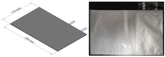
Figure 1.
Design diagram and actual photo of the prototype battery.
2.4. Characterization Methods
X-ray diffraction (XRD) patterns were obtained using a powder X-ray diffraction platform (D8 Advance, Bruker, Billerica, MA, USA, using Cu-Kβ radiation as the primary source, angle reproducibility < 0.0001, angle accuracy < 0.0001, and a maximum generator power of 3 kW). Scanning electron microscope (SEM) analysis was performed on a Hatachi Regulus 8100 (Hatachi, Tokyo, Japan) with an acceleration voltage of 15 kV and a secondary electron resolution of 0.8 nm to observe the morphology and surface changes of the samples. Transmission electron microscope (TEM) and high-resolution TEM (HRTEM) analyses were conducted on a HATACHI JEM F200 (Hatachi, Tokyo, Japan) with a maximum acceleration voltage of 200 kV, lattice resolution of 0.1 nm, point resolution of 0.24 nm, and information resolution of 0.16 nm to observe the superstructure of sample particles and edges. X-ray photoelectron spectroscope (XPS) characterization was performed on a PHI 500 VersaProbe III (ULVAC, Chigasaki, Japan) with an energy resolution of Ag 3d5/2 peak FWHM < 0.48 eV and a maximum beam current of the Ar ion sputtering gun of >5 μA @ 5 kV. The Brunner–Emmett–Teller (BET) test was conducted by fast fully automatic specific surface area and pore size distribution analyzer (NOVAtouch, Anton Paar, Graz, Austria, porosity 3.5–5000 Å, resolution < 0.01 m2/g). The element loading on the surface of the sample was measured via inductively coupled plasma-optical emission spectrometry (ICP-OES) utilizing the Avio 200 instrument, featuring a blaze angle of 63.8°, a spectral range spanning 165–900 nm, and a resolution of less than 0.009 nm @ 200 nm.
2.5. Thermal Runaway Test Methods
The formed prototype battery was connected to the Neware battery charging and discharging tester, and a thermocouple was used to measure the temperature near the tab on the upper surface of the battery. The thermal runaway behavior of LB-0 was tested using 1 C, 2 C, and 4 C rates to determine the optimal overcharge rate. Subsequently, LB-2–LB-6 were tested for overcharging at high rates, recording voltage and temperature changes during the process to analyze the impact of composite anode materials on thermal runaway caused by overcharging.
Besides thermal runaway caused by overcharging, this experiment also conducted a thermal runaway test on the prototype battery using a flame-triggered thermal runaway test chamber, as shown in Figure 2. The prototype battery was placed in the center of a mesh tray positioned at the bottom center of the upper chamber, with the flame nozzle directly facing the middle position between the two tabs on the lower surface of the battery (as shown in Figure 3a flame point). Three thermocouples were placed at the front, middle, and end of the battery’s upper surface to measure the surface temperature (as shown in Figure 3b). A gas sensor was set up inside the top of the test chamber to monitor the CO concentration in the test chamber. A thermal runaway reaction was triggered by applying a flame to the flame point. When the thermal runaway reaction occurred, the application of the flame was stopped. After the open flame had been extinguished, the gaseous products leaked from the thermal runaway were collected 50 mm above the battery and qualitatively and semi-quantitatively analyzed using Hapsite.
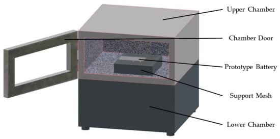
Figure 2.
Thermal runaway test chamber of lithium-ion batteries triggered by flame.

Figure 3.
Flame impingement point and thermocouple measurement point; (a) shows the lower surface of the battery; (b) shows the upper surface of the battery; flame point shows flame impingement point; thermocouple 1–3 shows the temperature measurement point.
3. Characterization of Anode Catalytic Material Performance
3.1. Physicochemical Properties and BET Characterization
To obtain the actual Au loading of AC002, ICP-OES testing was performed according to the detection method of the JY/T0567-2020 standard [22]. The results, as shown in Table 1, indicate that the actual Au loading is 1.71%, slightly less than the theoretical loading of 2%. This suggests that the choice of precipitant and the centrifugation and washing process during preparation can lead to the loss of Au. Simultaneously, Table 1 also lists the BET test results of the self-made catalyst. Compared with commercially available ordinary CeO2, the self-made catalyst has a higher specific surface area, which is mainly attributed to its petal-like surface microstructure.

Table 1.
BET and ICP-OES Test Results of Self-made Catalysts.
Figure 4 shows the XRD patterns of the self-made supported catalyst. Characteristic diffraction peaks (111), (200), (220), and (311) of the cubic fluorite structure CeO2 can be observed in both C001 and AC002 (JCPDS 43-1002). Moreover, weak characteristic peaks (111) and (200) of Au nanoparticles can be observed at 2θ = 38.122° and 44.380° in the XRD pattern of AC002. This indicates that Au particles are well dispersed on the surface of CeO2 with small crystal grains, resulting in low diffraction peak intensity. Simultaneously, the lattice constant of CeO2 in the AC002 catalyst is smaller than that in the pure C001 catalyst, suggesting that some Au species are doped into the lattice of CeO2, forming an Au-Ce alloy and utilizing oxygen vacancies to increase the interaction between nanometals and catalyst supports, effectively enhancing the sample activity through strong interactions between metal and metal oxides.

Figure 4.
XRD Characterization of C001 and AC002 Catalysts.
3.2. SEM Characterization
To study the morphological characteristics of the self-made catalyst, SEM analysis was performed on the prepared C001 and AC002 catalysts, as shown in Figure 5 and Figure 6. The SEM image in Figure 5a shows that the CeO2-based catalyst carrier C001 prepared in the laboratory exhibits a regular spherical morphology with a relatively uniform size distribution, with a particle size ranging from 3 μm to 7 μm and an average particle size of 4.63 μm (as shown in Figure 5d). Figure 5b,c show that the surface of C001 is uniformly distributed with petal-like mesoporous structures ranging from 1 nm to 20 nm. The advantages of this structure are as follows: on the one hand, it increases the comparative area and provides more catalytic active sites; on the other hand, it can effectively inhibit the agglomeration of nanometal particles loaded on it.
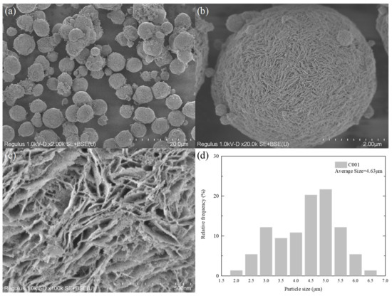
Figure 5.
SEM characterization of C001 catalyst; (a–c) at different magnifications; (d) particle size distribution.
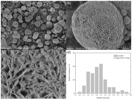
Figure 6.
SEM characterization of AC002 catalyst; (a–c) at different magnifications; (d) particle size distribution.
Figure 6 shows the SEM images of the catalyst AC002 loaded with nano-Au. As can be clearly observed from Figure 6a, the morphology of the catalyst did not change significantly before and after loading, maintaining a uniform microsphere structure with a particle size ranging from 3 μm to 7 μm and an average particle size of 4.35 μm (as shown in Figure 6d). Thanks to the excellent loading and separation effect of the petal-like structure on the surface of C001, the nano-Au particles loaded on the microsphere surface were able to maintain their nanometer size for a long time, thus prolonging the service life of the catalyst. Therefore, it can maintain the catalytic activity of nano-Au particles at high temperatures after thermal runaway of lithium-ion batteries.
3.3. Transmission Electron Microscope Characterization
To further analyze the microstructure and crystallinity of the AC002 sample, TEM and HRTEM characterizations were performed. Figure 7 shows the crystal morphology structure and particle size distribution of the AC002 catalyst at different magnifications. Figure 7c shows that the size of ceria microspheres ranged from 3 μm to 5 μm, which is consistent with the SEM observation. Meanwhile, nano-Au particles were uniformly distributed on the surface of CeO2 microspheres, covering the petal-like mesoporous structure (as shown in Figure 6c). According to the HRTEM images (Figure 7a,b), the Au/CeO2 catalyst is a polycrystalline structure composed of nanocrystals with different crystal orientations. Among them, the lattice spacings of 0.27 nm and 0.31 nm correspond to the (200) and (111) crystal planes of CeO2, respectively, while the less obvious lattice spacing of 0.23 nm corresponds to the (111) crystal plane of Au. The particle size statistics of nano-Au particles are shown in Figure 7d, indicating that most Au particles had a particle size ranging from 4 nm to 5 nm, with an average particle size of 4.78 nm, which also verifies the weak Au diffraction peaks in XRD.
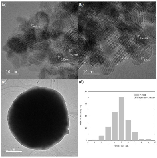
Figure 7.
The HRTEM images of the AC002 at different magnification; (a,b) the crystal planes of Au and CeO2; (c) the overall AC002 morphology; (d) the particle size distribution of AC002.
3.4. XPS Characterization
XPS characterization was performed on the prepared AC002 catalyst to detect surface active sites and obtain element states. The peak fitting results are shown in Figure 8, and the corresponding peak areas and surface content ratios are listed in Table 2.
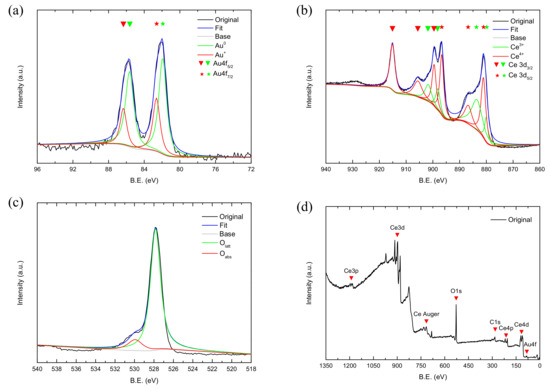
Figure 8.
XPS characterization results of AC002 Catalyst; (a) Au 4f; (b) Ce 3d; (c) O 1s; (d) Survey.

Table 2.
XPS peak fitting results of AC002 catalyst.
Figure 8a shows the XPS spectrum of Au 4f, with a characteristic peak at 82 eV and 85.6 eV, which can be fitted into two pairs of characteristic peaks. Among them, the characteristic peaks at BE = 81.9 eV and 82.6 eV correspond to Au 4f7/2, and the characteristic peaks at BE = 85.6 eV and 86.3 eV correspond to Au 4f5/2 [23]. A consensus has not yet been reached on the reason for the binding energy of Au 4f7/2 being lower than that of pure gold (84.0 eV) and it may be due to differences in the size, crystal form, and arrangement of gold nanoparticles [24,25]. The characteristic peaks with binding energies of 81.9 eV and 85.6 eV are attributed to Au0, while those with binding energies of 82.6 eV and 86.3 eV are attributed to Au+. No characteristic peak of Au2+ was observed because the high-temperature treatment converts all Au oxides and hydroxides into Au0. Figure 8b is the XPS spectrum of Ce 3d, which can be fitted into two groups of characteristic peaks. Among them, the characteristic peaks at BE = 880.0 eV, 881.1 eV, 883.5 eV, 886.8 eV, and 896.7 eV correspond to Ce 3d5/2, while those at BE = 898.1 eV, 899.5 eV, 901.7 eV, 905.5 eV, and 915.1 eV correspond to Ce 3d3/2. The characteristic peaks at BE = 880.0 eV, 883.5 eV, 898.1 eV, and 901.7 eV are attributed to Ce3+, while the remaining characteristic peaks are attributed to Ce4+. When Au nanoparticles are loaded on CeO2 materials, a reaction such as Equation (1) can occur.
Through this reaction, although the surface concentration of Au0 is reduced, on the one hand, the interaction between interfaces can significantly enhance catalytic activity, and, on the other hand, the conversion between Ce4+ and Ce3+ increases the surface oxygen defect sites, thereby enhancing the oxygen storage capacity of the catalyst. Meanwhile, some studies have also shown that Au+ has an empty d orbit and can activate CO, thus also enhancing catalytic activity [26].
Figure 8c is the XPS spectrum of O 1 s, where an asymmetric peak can be observed when BE is between 524.0 eV and 532.0 eV. After fitting, the characteristic peak with a binding energy of 527.8 eV is attributed to surface lattice oxygen Olatt, while the characteristic peak with a binding energy of 529.9 eV is attributed to oxygen defect/chemisorbed oxygen Oads. Among them, adsorbed oxygen has extremely high activity and reacts first with CO when it comes into contact with it. Therefore, a higher proportion of adsorbed oxygen facilitates the oxidation of CO.
3.5. Performance of Catalytic Oxidation of CO
To test the oxidation ability of the AC002 catalyst towards CO, the AC002 catalyst was tested using a fixed-bed reactor. The results are shown in Figure 9 and Figure 10. After introducing a gas containing 10,000 ppm of CO into the reactor, the composition of the gas exiting the reactor was monitored. The CO content in the effluent gas dropped to below 10 ppm within 10 min. As time increased, CO continued to decrease, and by 60 min, the CO concentration had dropped to 3.2 ppm, with an effective CO elimination rate exceeding 99.97% (as shown in Figure 10). This indicates that the catalyst exhibits excellent reactivity towards CO at room temperature. At the high temperatures associated with thermal runaway, it can more rapidly process the CO generated before the thermal runaway of lithium-ion batteries, quickly oxidizing it to CO2.
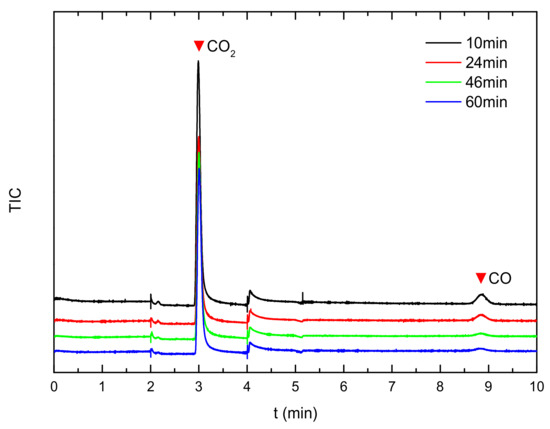
Figure 9.
GC analysis of product gas.
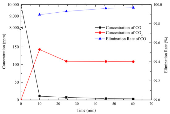
Figure 10.
Residual concentration and elimination rate of CO.
4. Performance and Thermal Runaway Testing of Prototype Batteries
4.1. Preparation of Anode and Electrochemical Performance
Considering that mixing graphite and the AC002 catalyst may affect both catalytic and electrical performance, we conducted electrochemical characterization and capacity testing on the composite anode material. The SEM images of the anode material CC-x (x = 0, 1, 2, 4, 6, 8, 10, 12) are shown in Figure 11a–h, indicating uniform mixing of the catalyst and graphite. However, as the loading increased, a small amount of catalyst aggregation occurred. Based on image analysis, the actual mixing ratio is shown in Figure 12.
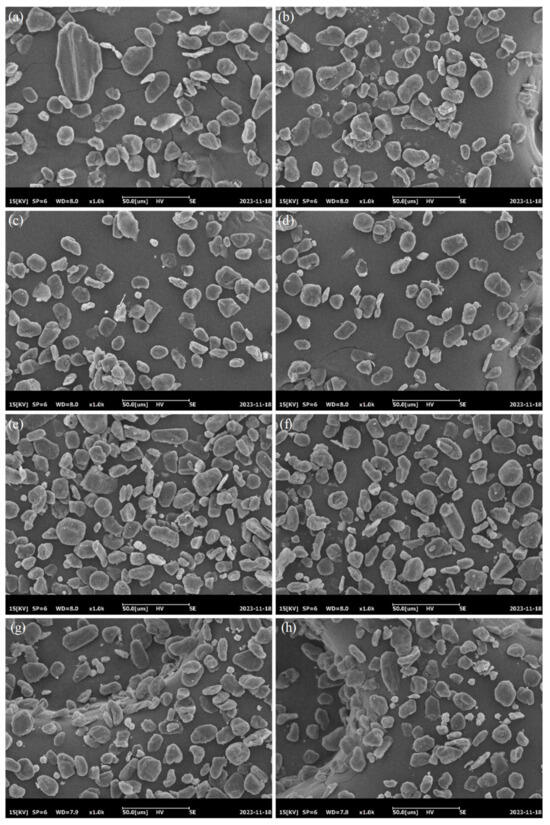
Figure 11.
SEM characterization of composite anode materials; (a) 0%; (b) 1%; (c) 2%; (d) 4%; (e) 6%; (f) 8%; (g) 10%; (h) 12%.
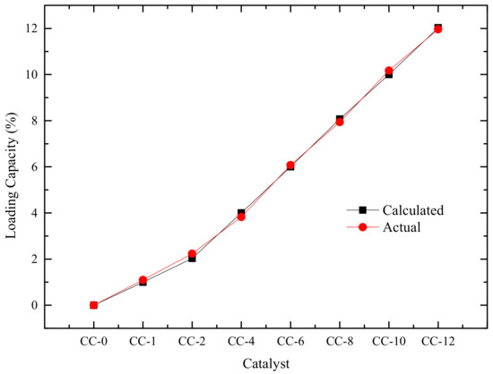
Figure 12.
Actual Mixing Rate of AC002 Catalyst.
The composite anode material was prepared as a slurry and coated on a Pt sheet electrode as the working electrode. A Pt sheet was used as the counter electrode, and a saturated calomel electrode served as the reference electrode. The electrolyte was 0.5 mol·L−1 sulfuric acid saturated with CO. Cyclic voltammetry testing was then performed, and the results are shown in Figure 13. The oxidation peak near 0.6 V corresponds to the oxidation of CO. Figure 14 summarizes the peak voltage, peak current, and integral area for the oxidation of CO on the electrode surfaces of composite anode materials with different loading amounts. As the loading increased, the oxidation peak voltage gradually increased, indicating that CO oxidation becomes more difficult with increasing loading. From the peak voltage and integral peak area, it can be seen that the catalytic performance of the composite material first increased and then decreased with increasing loading, exhibiting good catalytic activity at a loading rate of 2–6%.
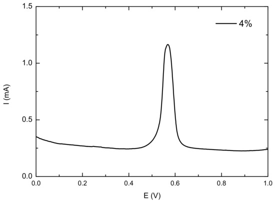
Figure 13.
CV test results of composite anode materials.
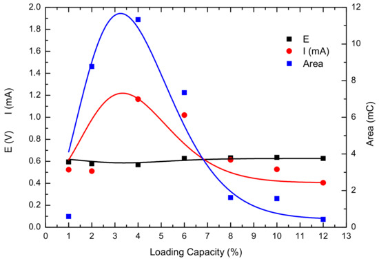
Figure 14.
Current, voltage, and integral area corresponding to CO oxidation peaks.
4.2. Battery Activation and Capacity Decay
Based on the study of electrochemical performance, we prepared prototype batteries with 2–6% AC002 catalyst added to the anode to investigate the effect of the catalyst on battery performance. After preparation, the batteries underwent a formation process for 100 h and were then charged to 100% SOC for standby use. During the formation process, we recorded the charging and discharging capacities for the first and last cycles, as well as the open-circuit voltage after the battery was fully charged, as shown in Figure 15. The open-circuit voltage of the battery LB-0 without additives was 4.1244 V at 100% SOC, while the open-circuit voltages (OCV) of the LB-2–LB-6 batteries at 100% SOC were slightly lower, ranging from 4.04 to 4.06 V. Throughout the formation process, the charging capacity of the LB-0 battery gradually stabilized at 70 mAh from the initial 101.56 mAh. The charging capacities of the LB-2–LB-6 batteries with AC002 catalyst added fluctuated more significantly, but the discharge capacities of all batteries remained within 72.00 mAh ± 0.04 mAh, indicating that the addition of the AC002 catalyst did not affect the battery capacity but may have had some impact on the stability of battery electrical performance.
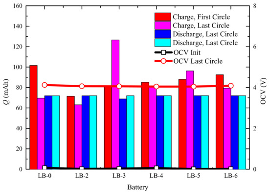
Figure 15.
Changes in Electrical Performance During Activation of Different Batteries.
4.3. Overcharge Testing
Overcharge testing was performed on the Neware CT4004 charge–discharge tester. Fully charged (100%SOC) batteries after formation were subjected to overcharge tests at 1 C (70 mA), 2 C, and 4 C rates, and voltage changes during the overcharge process were recorded (as shown in Figure 16). During the 1 C and 2 C overcharge processes, the voltage slowly increased with the state of charge until it reached 200% SOC, without any thermal runaway occurring. The ending charge voltages were 5.1562 V and 5.7700 V, respectively. This may be due to the relatively small amount of electrode material in the battery, where the self-generated heat and the heat released by the electrode reaction at normal rates are not enough to trigger further thermal runaway reactions. However, during the 4 C charging process, the voltage began to rise sharply after 700 s, showing clear signs of thermal runaway, which is consistent with a related report [27], and the anode–electrolyte reaction contributed significantly to the rate charging process.
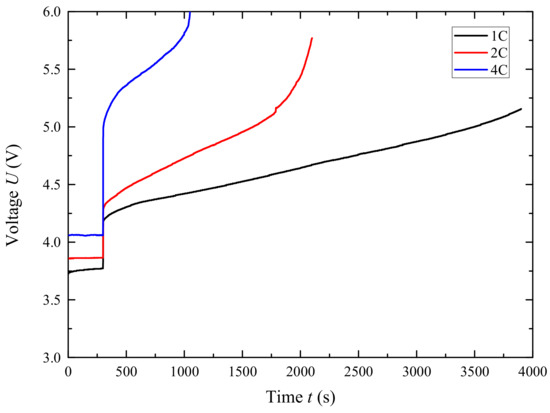
Figure 16.
Voltage curve under different charge rates.
Subsequently, LB-x (x = 0, 2–6) batteries were subjected to overcharge tests at a 4 C (280 mA) charging rate. The voltage and temperature changes of the test batteries were recorded as shown in Figure 17. Taking LB-0 as an example, after 870 s of overcharging, the battery voltage began to rise significantly. Around 1000 s, it suddenly surged and then dropped sharply, and the corresponding temperature curve also began to rise sharply. It is speculated that as overcharging progressed, changes occurred in the separator, leading to irreversible thermal runaway in the battery. Compared to the LB-0 without a catalyst, the initial voltage rise time for LB-2 to LB-6 was delayed by 30 s to 50 s, and the time to reach peak voltage was also delayed by 40 s to 410 s.
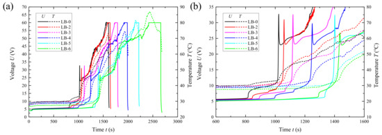
Figure 17.
Voltage and temperature variation with time during the overcharging process of prototype batteries (a); Partial enlarged view of the voltage range from 0 V to 35 V and the time range from 600 s to 1600 s in the complete curve (b).
According to Figure 18a, the surface temperature of various lithium-ion batteries rises dramatically at 33 °C ± 1 °C. However, under the same voltage, the battery with additives at the negative electrode exhibits a lower temperature (Figure 18b). Combining the above analysis indicates that the addition of the catalyst contributes to the stability of the battery under overcharging conditions, delaying the time of thermal runaway. Nevertheless, it does not significantly affect the initial temperature of thermal runaway in lithium-ion batteries.
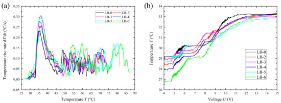
Figure 18.
Temperature-rise curve (a) and voltage–temperature curve (b) of prototype batteries during overcharging.
4.4. Thermal Runaway Testing
For pouch batteries, a typical thermal runaway process involves swelling, leakage of electrolyte/gaseous substances, opening of the safety valve/rupture of the packaging, and emission of smoke/flames. The thermal runaway test was conducted according to the flame-triggered thermal runaway experimental method described in Section 2.5. Typically, the commencement of thermal runaway is marked by battery temperature and temperature rise rate. However, due to the thinness of the battery and the significant influence of the flame on surface temperature, it was difficult to reflect the internal characteristics of a typical battery. Otherwise, thermal runaway is often accompanied by the release of CO within a short period, so the occurrence of thermal runaway, in this study, was marked by changes in CO concentration.
The analysis results of gaseous products are shown in Figure 19 and Table 3, while CO concentrations are presented in Figure 20. The main gaseous products detected after thermal runaway of the lithium-ion battery without a catalyst added mainly include (z)2-butene, dimethyl ether, benzene, fluorobenzene, and ethyl methyl carbonate (EMC). With the addition of the catalyst, the concentrations of various gaseous products decreased significantly, with the maximum material peak intensity reduced by 48.8–59.4% and the total ion current (TIC) intensity reduced by 27.1–31.6%, which indicates that both the concentration of the species with the highest concentration in the thermal runaway products and the total amount of gaseous products decreased significantly. This may be because CO produced early in thermal runaway is rapidly oxidized to CO2 under the action of the catalyst, reducing the carbon source and intermediates for subsequent reactions, thereby reducing the generation of toxic and harmful gaseous products during thermal runaway.
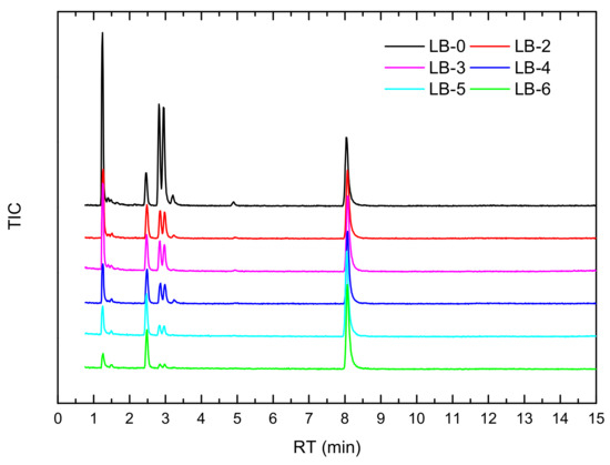
Figure 19.
Hapsite detection results of thermal runaway products of self-made lithium-ion batteries.

Table 3.
Main gaseous products of thermal runaway of self-made lithium-ion batteries.
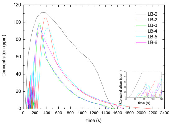
Figure 20.
Changes in CO concentration after thermal runaway of self-made lithium-ion batteries.
This can also be proven from Figure 20. CO was detected in LB-0 after 36 s of heating, and the CO concentration gradually increased, reaching a maximum value of 112 ppm after 267 s. The time for detecting CO in each lithium-ion battery after adding the catalyst was delayed, and both the peak CO concentration and integral concentration decreased (as shown in Table 3). Meanwhile, it can be observed in the inset of Figure 20 that after adding the catalyst, the CO concentration exhibited fluctuations in the early stage of thermal runaway, indicating that the catalyst has a good effect in promptly eliminating CO and delaying thermal runaway in the early stage.
5. Conclusions
In summary, this study successfully developed a new type of supported Au/CeO2 catalyst, providing a new strategy for improving the safety of lithium-ion batteries. The catalyst exhibits good performance in reducing toxic gases generated by thermal runaway and delaying the process of thermal runaway, providing strong support for the safe application of lithium-ion batteries. Future research can further explore the optimization of the catalyst and the improvement of battery performance to promote the continuous development and progress of lithium-ion battery technology.
In this study, a supported Au/CeO2 catalyst was prepared and applied to the anode of a lithium-ion battery, aiming to explore its impact on battery thermal runaway and thereby improve the safety of lithium-ion batteries.
- (1)
- The Au/CeO2 catalyst, prepared via the hydrothermal method, possesses a favorable flower-like surface structure, providing a high specific surface area of 92.868 m2·g−1. This structure also prevents the aggregation of supported Au. Characterization techniques such as XRD and SEM confirmed the uniform dispersion of Au particles on the catalyst support surface. XPS analysis indicated that the synergistic effect between metal and metal oxide effectively enhances the catalytic activity of the catalyst.
- (2)
- The catalytic oxidation performance of the supported catalyst for CO was evaluated using a fixed-bed reactor. The results showed that the CO concentration could be reduced from 10,000 ppm to 10 ppm within 10 min, reaching a minimum of 3.2 ppm within 60 min. The effective elimination rate of CO exceeded 99.97%, demonstrating the catalyst’s excellent CO catalytic activity.
- (3)
- Prototype batteries were fabricated using composite anode materials consisting of different proportions of catalyst and graphite. After 100 h of formation, the OCV of the battery with added catalyst stabilized at 4.05 V ± 0.01 V, with a discharge capacity maintained at 72.00 mAh ± 0.04 mAh. This suggests that the addition of the catalyst did not cause capacity fading.
- (4)
- In overcharging tests, the catalyst significantly prolonged the battery’s voltage rise time and the time to reach peak voltage, indicating its delaying effect on thermal runaway. During thermal runaway tests, the concentration of thermal runaway products, especially the peak and integrated concentrations of CO, were significantly reduced in batteries with added catalyst. This further demonstrates the catalyst’s effectiveness in reducing thermal runaway products.
In future research, attempts can be made to apply this catalytic material to larger capacity lithium-ion batteries with various systems. Additionally, modification studies can be conducted to minimize the material’s impact on battery stability, enhance the prevention and delaying effects on lithium-ion battery thermal runaway, and effectively improve the safety of lithium-ion batteries.
Author Contributions
Conceptualization, J.S.; Data curation, T.Z.; Formal analysis, T.Z. and F.Z.; Investigation, T.Z., J.S., J.L., S.W., F.Z., and J.C.; Methodology, T.Z., J.S., and J.L.; Resources, J.S.; Software, T.Z.; Validation, J.S.; Visualization, T.Z.; Writing—original draft, T.Z.; Writing—review & editing, J.S. All authors have read and agreed to the published version of the manuscript.
Funding
This research was funded by Standard Compilation Project, grant number 145BZB210013420X and Youth Preparatory Research Fund of Institute of NBC Defence, grant number YuanKe[2023]22.
Data Availability Statement
The data presented in this study are available in this article.
Acknowledgments
The research team would like to thank Li Quan from the key laboratory for renewable energy, CAS, for his assistance in assembling the prototype battery and the Tianmu Lake institute of advanced energy storage technologies for the structural characterization test.
Conflicts of Interest
The authors declare no conflicts of interest.
References
- Miao, Y.; Hynan, P.; Von Jouanne, A.; Yokochi, A. Current Li-Ion Battery Technologies in Electric Vehicles and Opportunities for Advancements. Energies 2019, 12, 1074. [Google Scholar] [CrossRef]
- Camp, D.; Vey, N.; Kylander, P.; Auld, S.; Willis, J.; Lussier, J.; Eldred, R.; Van Bossuyt, D. Li-ion Batteries and the Electrification of the Fleet. Nav. Eng. J. 2023, 135, 169–184. [Google Scholar]
- Yao, W.-B.; Wang, K.-Y.; Sun, J.-H. Study of Li-ion Battery Exchange Stations in Future Power System. In Proceedings of the 2022 IEEE 9th International Conference on Power Electronics Systems and Applications, PESA, Hong Kong, China, 20–22 September 2022. [Google Scholar]
- Deng, D. Li-ion batteries: Basics, progress, and challenges. Energy Sci. Eng. 2015, 3, 385–418. [Google Scholar] [CrossRef]
- Shin, Y.; Ahn, K.; Lee, C.; Kang, B. A self-discharging reaction mediated by imide salt enables the prevention of explosive thermal runaway in high-Ni material/graphite full cells. J. Mater. Chem. A 2023, 11, 23556–23565. [Google Scholar] [CrossRef]
- Zu, C.; Li, J.; Cai, B.; Qiu, J.; Zhao, Y.; Yang, Q.; Li, H.; Yu, H. Separators with reactive metal oxide coatings for dendrite-free lithium metal anodes. J. Power Sources 2023, 555, 232336. [Google Scholar] [CrossRef]
- Wei, C.; Zhang, Y.; Lee, S.-J.; Mu, L.; Liu, J.; Wang, C.; Yang, Y.; Doeff, M.; Pianetta, P.; Nordlund, D.; et al. Thermally driven mesoscale chemomechanical interplay in Li0.5Ni0.6Mn0.2Co0.2O2 cathode materials. J. Mater. Chem. A 2018, 6, 23055–23061. [Google Scholar] [CrossRef]
- Allcom, E.; Manthiram, A. Thermal Stability of Sb and Cu2Sb Anodes in Lithium-Ion Batteries. J. Electrochem. Soc. 2015, 162, A1778–A1786. [Google Scholar]
- Liu, H.M.; Saikia, D.; Wu, H.C.; Su, C.Y.; Wang, T.H.; Li, Y.H.; Pan, J.P.; Kao, H.M. Towards an understanding of the role of hyper-branched oligomers coated on cathodes, in the safety mechanism of lithium-ion batteries. RSC Adv. 2014, 4, 56147–56155. [Google Scholar] [CrossRef]
- SanSangsanit, T.; Homlamai, K.; Joraleechanchai, N.; Prempluem, S.; Tejangkura, W.; Sawangphruk, M. Non-flammable electrolyte for large-scale Ni-rich Li-ion batteries: Reducing thermal runaway risks. J. Power Sources 2024, 594, 234021. [Google Scholar] [CrossRef]
- Baakaes, F.; Witt, D.; Krewer, U. Impact of electrolyte impurities and SEI composition on battery safety. Chem. Sci. 2023, 14, 13783–13798. [Google Scholar] [CrossRef]
- Li, Y.; Ding, F.; Shao, Y.; Wang, H.; Guo, X.; Liu, C.; Sui, X.; Sun, G.; Zhou, J.; Wang, Z. Solvation Structure and Derived Interphase Tuning for High-Voltage Ni-Rich Lithium Metal Batteries with High Safety Using Gem-Difluorinated Ionic Liquid Based Dual-Salt Electrolytes. Angew. Chem. 2024, 136, e202317148. [Google Scholar] [CrossRef]
- Kizilel, R.; Sabbah, R.; Sveum, P.; Selman, J.-R.; Al-Hallaj, S. Prevention of thermal runaway propagation in a Li-ion battery pack. In Proceedings of the 2007 IEEE Vehicle Power and Propulsion Conference, Arlington, TX, USA, 9–12 September 2007; Volumes 1–2, pp. 344–347. [Google Scholar]
- Yang, C.; Sunderlin, N.; Wang, W.; Churchill, C.; Keyser, M. Compressible battery foams to prevent cascading thermal runaway in Li-ion pouch batteries. J. Power Sources 2022, 541, 231666. [Google Scholar] [CrossRef]
- Sun, Z.; Guo, Y.; Zhang, C.; Xu, H.; Zhou, Q.; Wang, C. A Novel Hybrid Battery Thermal Managament System for Prevention of Thermal Runaway Propagation. IEEE Trans. Transp. Electrif. 2024, 9, 5028–5038. [Google Scholar] [CrossRef]
- Zhang, L.; Liu, L.; Yang, S.; Xie, Z.; Zhang, F.; Zhao, P. Experimental investigation on thermal runaway suspension with battery health retention. Appl. Therm. Eng. 2023, 225, 120239. [Google Scholar] [CrossRef]
- Sun, J.; Li, J.; Zhou, T.; Yang, K.; Wei, S.; Tang, N.; Dang, N.; Li, H.; Qiu, X.; Chen, L. Toxicity, a serious concern of thermal runaway from commercial Li-ion battery. Nano Energy 2016, 27, 313–319. [Google Scholar] [CrossRef]
- Li, T.-Y.; Jiao, Y.-H. Revealing the Thermal Runaway Behavior of Lithium Iron Phosphate Power Batteries at Different States of Charge and Operating Environment. Int. J. Electrochem. Sci. 2023, 17, 221030. [Google Scholar] [CrossRef]
- Jindal, P.; Bhattacharya, J. Review-Understanding the Thermal Runaway Behavior of Li-Ion Batteries through Experimental Techniques. J. Electrochem. Soc. 2019, 166, A2165–A2193. [Google Scholar] [CrossRef]
- Zhao, P.; Liu, L.; Zhang, L.; Chen, Y. Mitigating battery thermal runaway through mild combustion. Chem. Eng. J. Adv. 2022, 9, 100208. [Google Scholar] [CrossRef]
- Feng, X.; Zheng, S.; He, X.; Wang, L.; Wang, Y.; Ren, D.; Ouyang, M. Time Sequence Map for Interpreting the Thermal Runaway Mechanism of Lithium-Ion Batteries with LiNixCoyMnzO2 Cathode. Front. Energy Res. 2019, 6, 126. [Google Scholar] [CrossRef]
- JY/T0567-2020; General Rules of Inductively Coupled Plasma Emission Spectroscopy Analysis Methods. Ministry of Education of the People’s Republic of China: Beijing, China, 2020.
- Tabakova, T.; Ilieva, L.; Ivanov, I.; Zanella, R.; Sobczak, J.W.; Lisowski, W.; Kaszkur, Z.; Andreeva, D. Influence of the preparation method and dopants nature on the WGS activity of gold catalysts supported on doped by transition metals ceria. Appl. Catal. B Environ. 2013, 136–137, 70–80. [Google Scholar] [CrossRef]
- Sham, T.K.; Kim, P.S.G.; Zhang, P. Electronic structure of Molecular-capped gold nanoparticles from X-ray spectroscopy studies: Implications for coulomb blockade, luminescence and non-Fermi behavior. Solid State Commun. 2006, 138, 553–557. [Google Scholar] [CrossRef]
- Arrii, S.; Morfin, F.; Renouprez, A.J.; Rousset, J.L. Oxidation of CO on Gold Supported Catalysts Prepared by Laser Vaporization: Direct Evidence of Support Contribution. J. Am. Chem. Soc. 2004, 126, 1199–1205. [Google Scholar] [CrossRef] [PubMed]
- Qiao, B.; Liang, J.X.; Wang, A.; Xu, C.Q.; Li, J.; Zhang, T.; Liu, J.J. Ultrastable single-atom gold catalysts with strong covalent metal-support interaction. Nano Res. 2015, 8, 2913–2924. [Google Scholar] [CrossRef]
- Li, Y.; Feng, X.; Ren, D.; Ouyang, M.; Lu, L.; Han, X. Thermal Runaway Triggered by Plated Lithium on the Anode after Fast Charging. ACS Appl. Mater. Interfaces 2019, 11, 46839–46850. [Google Scholar] [CrossRef] [PubMed]
Disclaimer/Publisher’s Note: The statements, opinions and data contained in all publications are solely those of the individual author(s) and contributor(s) and not of MDPI and/or the editor(s). MDPI and/or the editor(s) disclaim responsibility for any injury to people or property resulting from any ideas, methods, instructions or products referred to in the content. |
© 2024 by the authors. Licensee MDPI, Basel, Switzerland. This article is an open access article distributed under the terms and conditions of the Creative Commons Attribution (CC BY) license (https://creativecommons.org/licenses/by/4.0/).