1. Introduction
To overcome the challenge of climate change, governments are globally promoting the sales of electric vehicles (EVs) [
1,
2,
3]. The global production and sales of EVs are growing steadily, driven by sustainability commitments and the rapid development of EV technology. In 2020, EV registrations increased by 41%, and the total number reached a new milestone of approximately 10 million units globally [
4]. The near future is expected to follow an upward trend, as the global number of electric vehicles is forecasted to exceed 300 million by the year 2030 [
5]. Lithium-ion batteries are utilized as the power storage for EVs because of their exceptional reliability, fast charging capability, high energy density, and long lifetime.
Electric vehicle batteries (EVBs) deteriorate, losing capacity over time due to charge and discharge cycles. When the EVB capacity falls below the 80% limit, it is no longer considered suitable for an EV and must be recycled or repurposed [
6,
7]. After decommissioning from automotive use, the state of health (SoH), state of risk (SoR), and remaining useful life (RUL) of the EVB must be defined to decide if EVB modules or cells are still usable in second-life applications; EVBs no longer suitable for automotive use may still be usable in other applications [
8], such as building energy storage systems (BESS). EVBs with mechanical damages or non-existent capacity are recycled into raw materials for new batteries. Efficient testing methods are required to sort the EVBs for repurposing or recycling.
While the electric driveline of the EVs is energy efficient and does not generate tailpipe emissions, the tradeoff is emissions generated during the manufacturing process of the batteries, starting from mining the required raw materials [
9]. In addition to emissions, mining causes environmental degradation and human health issues [
10,
11,
12,
13]. Efficient concepts for recycling and repurposing existing EVBs are required to reduce the need for mining raw materials and manufacturing new batteries to decrease the side effects of mining. EU Battery directive [
14] aims to promote the utilization of recycled materials in battery manufacturing by defining requirements for minimum percentages for recycled materials and requiring the manufacturers to collect and recycle the used batteries, including EVBs.
The recycling process for EVBs is diverse, depending on the SoH, SoR, and RUL testing results. The end-of-life EVBs are first discharged, and after discharge, the battery is shredded to black mass; which contains valuable materials [
15], such as lithium, nickel, cobalt, and manganese. The black mass is decomposed into raw materials using hydrometallurgical, pyrometallurgical, or mechanical processes [
16,
17,
18].
The discharging and shredding procedure is not sustainable for EVBs with sufficient capacity for second-life purposes. For repurposing, EVBs must be dismantled to the module or cell level without damaging the battery cells. Because deep discharging damages the lithium-ion battery, dismantling must be carried out without discharging the battery, which entails a significant risk associated with the process [
19,
20]. Ensuring safety is essential in dismantling a charged EVB; the dismantling environment is hazardous, posing risks of toxic chemicals, fire, electric arcs, and electrocution. Risks can be reduced by using robots in the dismantling process [
21,
22], but the deployment of fully autonomous robots for battery discharge is still in its early stages of development. This necessitates human presence in the operation, demanding continued attention to safety protocols [
23,
24].
EVBs feature an integrated battery monitoring system (BMS) to monitor the battery during daily automotive usage. The BMS monitors temperature, current, and voltage data to balance the EVB cells during charging and to protect the battery by electrically isolating the EVB from the vehicle’s drivetrain if abnormalities are detected. Additionally, the BMS features the algorithms to define the SoH and state of charge (SoC) of the EVB. BMS utilizes the controller area network (CAN) to communicate with other vehicle subsystems and service diagnostic equipment. Utilizing the SoH and SoC data collected by the BMS during the testing phase enables streamlining the sorting of EVBs for recycling and repurposing. The temperature and voltage sensors can also be utilized to monitor the battery during dismantling and storage. While approaches to using BMS data in the recycling of consumer batteries have been proposed [
25], research on using the CAN interface to assess the SoH and SoR in the EVB recycling is absent.
This publication presents an approach to assess the EVB parameters essential to recycling and repurposing using the integrated BMS. The CAN interface is utilized to extract the data from the BMS. An embedded system extracts and saves the data to a cloud server for further processing, aiming to evaluate the SoH, RUL, and SoR of the EVB. The contributions of the publication are as follows:
The rest of this paper is organized as follows:
Section 2 presents background and a review of battery safety issues and the usage of the CAN interface in EVBs.
Section 3 overviews the methods and materials used to implement the CAN-based EVB data collection and evaluation.
Section 4 presents test results and
Section 5 discusses the results, answering the research questions.
Section 6 concludes the study.
2. Background and Related Research
This section overviews safety in battery processing and techniques to extract data from the BMS. The first subsection reviews and summarizes the new EU battery regulations and the battery passport proposal. The second subsection overviews battery safety from a chemical perspective, focusing on abnormal conditions. The following subsections present the EVB testing methods, the role of the BMS and the CAN interface in EVB monitoring, and previous research on extracting data from batteries using the CAN interface. The last subsection presents the research gap for this publication.
2.1. Battery Regulations and Passport
EU battery regulation [
14] defines requirements for sustainability, safety, labeling, and information on the batteries sold and used in the EU. Manufacturers are obliged to set up procedures for collecting and recycling end-of-life batteries, including collection points available to all citizens free of charge. Additionally, manufacturers and distributors must process and recycle used batteries, including EVBs. To promote sustainability and energy efficiency in battery manufacturing, after 18 August 2031, the directive demands new batteries sold in the EU to contain at least 16%, 6%, and 6% of recycled cobalt, lithium, and nickel, respectively.
Besides the new battery directive, the EU Commission has prepared a proposal for a digital battery passport to validate the authenticity of new and used EVBs [
26]. The proposal obliges manufacturers to label new batteries with unique labels such as QR-codes to identify the batteries and interact with the Electronic exchange system; a database containing comprehensive information about the battery. The database is proposed to include disassembly, spare parts, materials, and SoH information of all the labeled batteries to ease the future disassembly, repurposing, and recycling.
2.2. Overview of Battery Safety
During the regular lithium-ion battery (LIB) operation, the only electrochemical reactions occurring are the half-cell reactions on the electrodes and the lithium-ion transport in the electrolyte between the electrodes. In a battery failure state, an exothermic chemical chain reaction called thermal runaway may occur [
27]. Thermal runaway of LIBs is a potentially catastrophic chain reaction leading to a violent and uncontrolled release of energy, causing heat, fire, or even an explosion. Several usage-related factors can contribute to thermal runaway, including overheating, physical damage, overcharging or over-discharging, and manufacturing defects [
28]. Additionally, external factors, such as extreme temperatures or exposure to flammable materials, increase the risk of thermal runaway.
Chemical hazards can arise during thermal runaway and other abnormal conditions if the cell is ruptured and internal chemicals are in contact with the atmosphere. Typical emissions from cells during a fire or thermal runaway include combustible gasses like volatile organic compounds (VOCs) and hydrogen(H
2), carbon monoxide (CO), carbon dioxide (CO
2), nitrogen oxide (NOx) and harmful inorganic gases such as hydrogen fluoride (HF), hydrogen chloride (HCl) and sulfur dioxide (SO
2). The gases released during thermal runaway are toxic for humans and can lead to asphyxiation [
29,
30].
The vented HF gas can cause harm to humans in the vicinity of a LIB fire or thermal runaway scenario. The most probable exposure to HF is inhalation. Exposure to HF vapor can cause irritation and damage to the airways as the acid reacts with mucosa, causing chemical burns that can result in swelling, bleeding, and severe damage to the tissues of the airways. In the worst case, the damage caused by HF inhalation may result in death. Skin exposure and ingestion of HF can likewise cause severe damage and even death due to deep chemical burns resulting from the exposure [
31].
Lithium-ion battery manufacturers incorporate various safety features and technologies into their designs, such as internal thermal management systems, venting mechanisms, and thermal cutoff devices to mitigate the risk of thermal runaway and potentially dangerous gas formation. Safe practices for charging, discharging, disassembly, storage, and handling lithium-ion batteries are essential to prevent incidents. Monitoring battery temperature and gas leakage during transportation and storage is essential in avoiding incidents caused by thermal runaway [
32].
2.3. Methods to Define the Battery State
Visual inspection is the first step to defining the SoR of the EVBs. Mechanically damaged or leaking EVBs unsafe to dismantle are recycled by crushing them as complete units [
33]. EVBs defined as safe are tested to define SoH and RUL to decide between repurposing or recycling.
Various methods have been proposed to define the SoH and RUL of the EVBs using direct, adaptive, and assessments based on artificial intelligence [
34]. Direct assessment methods include Coulomb counting (CC), open circuit voltage (OCV), and impedance spectroscopy (IES). The charging-discharging test utilizing the CC method is a common way to find out the current capacity of the EVB to define the SoH by comparing the current capacity to the nominal capacity. Ng et al. [
35] presented an approach based on charge-discharge cycling to define the SoH. The accuracy of the CC method is 10% and can be improved to 3% by adding a Kalman filter (KF). Weng et al. [
36] utilized OCV assessment to define the SoH of used EVBs.
SoC is an important parameter in quantifying the remaining capacity of EVB by comparing the current capacity to the nominal total capacity. SoC represents the percentage of available energy stored in the battery at a given time, indicating the charge of the battery, ranging from 0% to 100% [
37]. However, charging batteries to 100% SoC for storage is not optimal, based on the findings of Keil et al. [
38], storing a lithium-ion cell above 50% SoC will drastically decrease its capacity over a long period. The effect is even more significant if the ambient temperature for storage is over 50 °C. The optimal SoC for storing batteries for extended periods is between 40% and 50%. This recommendation applies particularly to second-life battery usage, where battery modules or cells may be stored for extended periods. In such cases, charging or discharging before storage is essential to optimize battery lifetime.
While these methods effectively define the state of the EVB, partial disassembly of the battery is required to gain access to cell voltage connectors. In practice, the EVB is first dismantled, and then individual modules are tested to define the SoH and RUL. Extracting the data from the BMS utilizing the CAN interface enables to avoid disassembling end-of-life EVBs by defining the state of the EVB before disassembly, significantly streamlining the sorting of EVBs.
Figure 1 presents the benefits of utilizing the CAN interface to access the BMS data to test the EVBs.
An approach to extracting the capacity, manufacturing date, and the number of charge-discharge cycles from notebook computer lithium-ion batteries utilizing a common bus was presented by Salinas et al. [
25]. The standard communication protocol between the notebook and the BMS is Inter-Integrated Circuit (I2C), and typically, notebook batteries consist of cylindrical 18,650 cells. In their work, an embedded system was connected to the clock and data signals of the I2C port of the batteries to read the required data from the BMS; 152 batteries in total were tested using the proposed approach, and a selection algorithm based on the dataset was developed to select the batteries with a remaining capacity of more than 70% for disassembly and reuse. The proposed approach saves time sorting the batteries for recycling raw materials and reusing them.
2.4. Battery Management System
The CAN interface is used in automotive applications to communicate between subsystems, including the BMS. The BMS is an essential component integrated into the EVB to monitor the battery module’s SoH, SoC, voltage, temperature, and current. To collect the data required for monitoring the battery modules, BMS features various analog and digital sensors [
39,
40]. While monitoring the battery, the BMS also controls cell balancing, charging disconnect, and cooling of the battery pack during the charging and discharging cycles; therefore, a failure in the BMS can lead to a thermal runaway caused by undercharged or overcharged battery modules. The BMS shares the collected data with other vehicle subsystems via the CAN interface.
2.5. The Controller Area Network
The development of the CAN was initiated in the early 1980s at Bosch (Robert Bosch GmbH, Gerlingen, Germany). Version 2.0B of the CAN was released in 1991 and has become a standard communication protocol in the automotive industry [
41,
42]. In addition to automotive applications, the CAN interface has been adopted for industrial applications. In modern vehicles, the CAN interface enables communication of various sub-systems, including braking, entertainment, safety, battery, and engine control.
The physical layer of CAN utilizes two wire differential signaling: CAN-High and CAN-Low. The voltage difference between the two determines the state of the signal. A voltage difference between 1.5 and 3.5 volts presents a logical 0, and a voltage difference less than 0.5 volts presents a logical 1. Differential signaling enables immunity to electromagnetic noise, making CAN suitable for noisy environments such as vehicles. CAN is a distributed system and does not require a dedicated master device; each device node can transmit and receive messages independently.
In automotive applications, it is common practice to have two separate CAN interfaces. The primary CAN interface enables high-speed communication for mission-critical powertrain, brake, and steering systems, and the secondary bus enables communication for instrumentation and entertainment systems. Utilizing two separate interfaces reduces devices on the primary interface and enables efficient mission-critical communication. For example, The BMS connects to the secondary interface to indicate the SoC and power consumption of the EVB and to the primary interface to activate the isolation contactor and thermal management system.
Versions 2.0A and 2.0B of the standard define two formats for the messages: standard and extended format. The difference between the two is the length of the identifier; the standard is 11-bit, and the extended is 29-bit long. CAN devices supporting the extended format also support the standard version format. The message itself consists of 8 bytes of data.
The CAN standard defines four types of message frames for communication: data, remote, error, and overload. The data frame is used to transmit actual data values, and the nodes use the remote frame to request a specific data value from another node. For example, a CAN diagnostic tool may request the vehicle identification number from the body control module. The latter two message types relate to error and overflow controlling of the CAN; the nodes can send an error frame if a network or frame error is detected, and the overload frame indicates delay transmissions if the receiving node’s buffer is overloaded [
43]. The Database CAN (DBC) is a structured text file describing the CAN frames used to decode the CAN messages. The most common way to utilize DBC is to load the file into CAN logger software. The DBC files are, in most cases, proprietary documents owned by vehicle manufacturers and are not publicly accessible.
Upon CAN message arrival, the message can be translated to human readable values using DBC definitions as illustrated in
Figure 2. The message must be converted to a sequence of bits before applying the DBC. Each definition starts with the message ID name, followed by the value details of the message. The next important part of a message is a starting bit number, followed by the length of the message in bits. After a bitwise operation to obtain the appropriate sequence of bits, the value of the message is transformed into a decimal value, multiplied by a scale factor, and finally summed with an offset value to obtain a human-readable value. The DBC also defines minimum and maximum values and the unit of the final result to help analyze the result [
44].
2.6. Research Gap
While numerous methods have been proposed for defining the SoH, SoC, and RUL of EVBs, scientific literature lacks solutions for utilizing BMS data via the CAN interface for EVB testing. This publication presents and evaluates an approach to utilize BMS data to assess battery condition before disassembling for recycling or repurposing. Additionally, monitoring battery temperature and SoC during offline charging or discharging is presented to achieve optimal SoC to store the EVB modules.
3. Materials and Methods
This section presents the materials and methods utilized to assess and monitor the state of the EVB. First, the overall test setup is presented, and then individual equipment details are explained. After introducing the materials involved, the methods utilized to extract and evaluate the BMS data using the CAN interface are described.
3.1. Test Setup
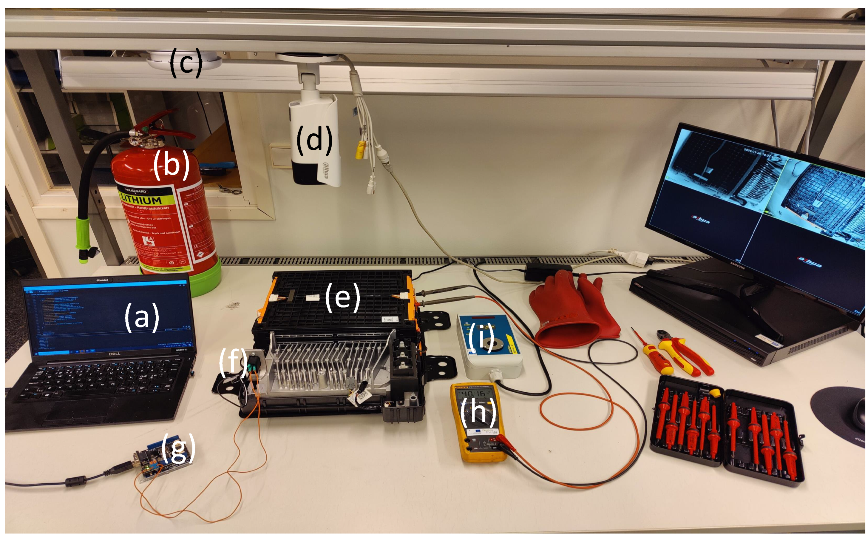
The testing setup illustrated in
Figure 3 enables safe testing and measurements of the EVB, alarming the staff to exit the laboratory in case of an emergency. A thermal camera and a hydrogen fluoride gas detector ensure the detection of abnormalities during the testing. The thermal camera can detect temperature fluctuations in the battery, and the hydrogen fluoride gas detector can identify potential gas leaks during the testing.
Various measuring and laboratory equipment are used to support the scientific deductions. This approach covers a broad spectrum of parameters and insights into battery performance and safety. The presented multifaceted methodology enhances the understanding of battery functionality and enables the implementation of the necessary enhancements for improved performance and safety. Listing of the test equipment and the EVB:
Mild hybrid EVB.
A thermal camera system [
45].
Arduino embedded system [
48] featuring CAN interface module [
49].
3.2. Electric Vehicle Battery
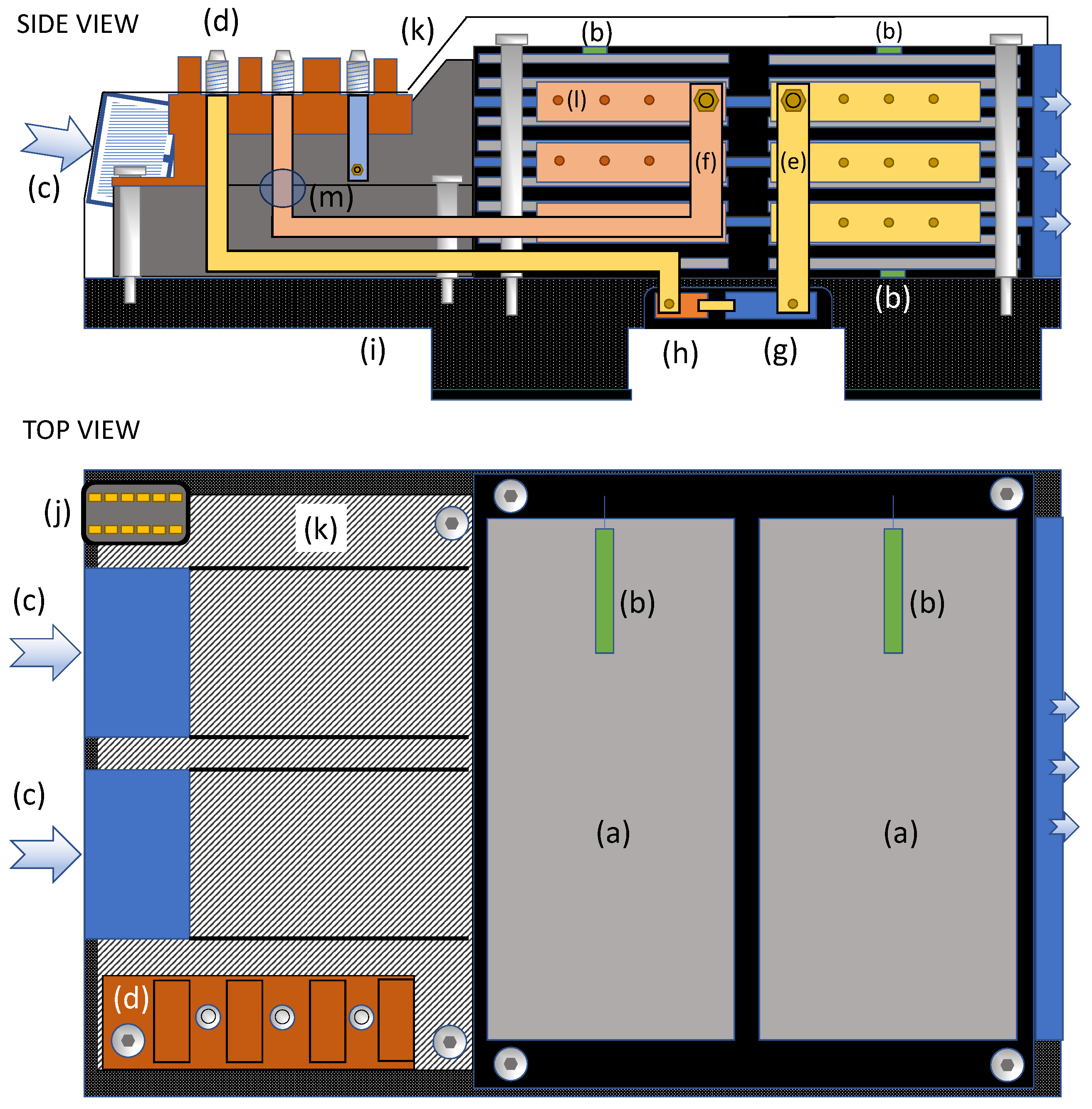
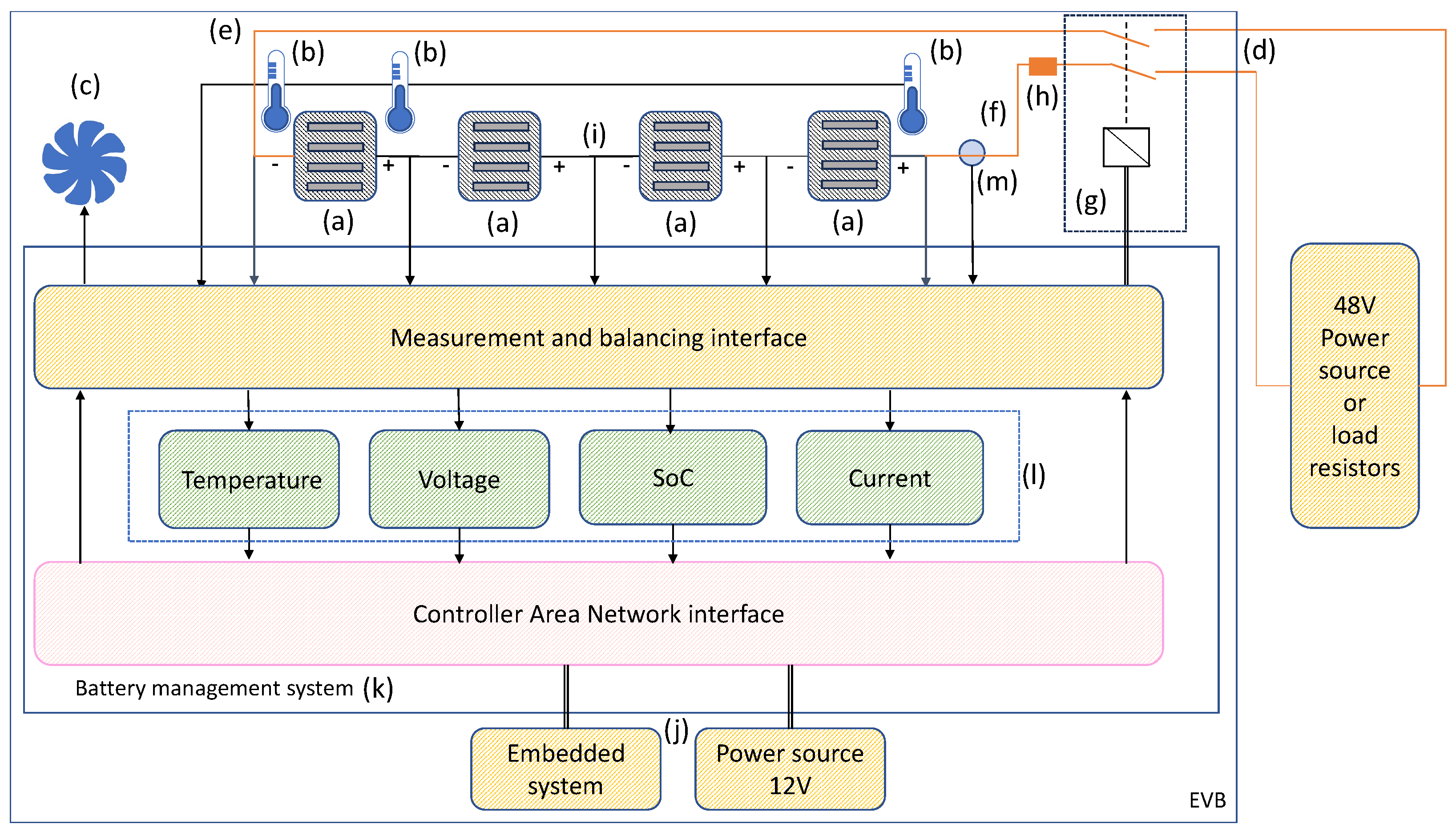
A cross-section view of the mild hybrid electric vehicle (MHEV) battery [
50] used in this study is presented in
Figure 4. The battery consists of sixteen individual battery cells packed into four 12 V modules, enabling a capacity of 430 Wh and a nominal voltage of 48 V. The battery was chosen for the study based on its relatively small size, enabling easy handling during the testing. Technically, the battery integrates all the typical features of larger lithium-ion batteries, including a BMS, CAN interfaces, and thermal management system, making it suitable for this study. The detailed specifications of the battery are presented below.
Voltage 48 V
Capacity: 9.8 Ah
Total Energy: 430 Wh
Usable SoC window: 40–72%
Continuous current: 75 A
Number of cells: 16
Cell type: Pouch
Maximum peak current: 250 A
Dimensions: 467 × 438 × 173 mm
Weight: 17.5 Kg
3.3. Thermal Camera System
During the tests, EVB is placed on a table, enabling mounting the thermal camera system [
45] above to monitor the pouch cells of the EVB. The table surface height is adjusted to fit the EVB cells in the camera field of view. By default, the thermal camera system presents two video streams: a black-and-white thermal camera stream and a color video stream with blue and red dot indicators presenting the coldest and hottest points on the thermal camera display. The thermal camera system triggers an alarm if an abnormality such as a thermal runaway is detected.
3.4. HF Gas Detector
An HF gas meter next to EVB detects and alarms for potential, though unlikely, leaks of hazardous HF gas. The gas meter will indicate the amount of HF gas near the battery and guarantee the tester’s safety in the event of a possible gas leak. Since HF gas is heavier than air [
51], the meter is near the EVB at approximately the same height. This case study uses a 0–10 ppm HF gas detector [
46].
A battery in a safe condition does not emit HF gas. If the meter deviates from the 0.0 ppm value, the battery is unsafe, necessitating immediate safety measures. The permissible exposure limit value (PEL) in the air is three ppm during an average 8-h work shift. Even a small gas amount of 0.04 ppm is capable of causing severe skin and respiratory symptoms in humans [
51]. Therefore, the HF gas meter triggers an alarm in case of detecting HF.
3.5. Embedded System to Extract the Battery Data
The embedded system used in this study is Arduino Uno WiFi [
48]. Uno Wifi has internal processing and memory capacity and fourteen configurable input and output pins. Five IO pins can be configured as PWM outputs and six as analog inputs. A USB connection between the board and a laptop is enabled to transfer the code to the Arduino. The integrated WiFi connectivity is used to upload the data extracted from the BMS to a cloud server. The Arduino integrated development environment [
52] enables the programming of the embedded system.
The CAN interface in this study is the CAN bus shield V2 (Seeed Technology Co., Ltd., Shenzhen, China), enabling communication between the Arduino and BMS. Interface conforms to CAN V2.0B communication standard, supporting the standard 11-bit and extended 29-bit data and remote frames.
The CAN interface mounts on the top of the Arduino board, and the screw terminal enables the connection to the EVB CAN interface.
3.6. Research Methods
This research begins with the background and related research study, in which common battery safety issues and various methods to monitor battery safety are mapped. Based on preliminary literature and the notified research gap, a plan to utilize the CAN interface to extract the BMS data is created, and the code for the embedded system is developed to extract the data using the CAN interface. The plan’s implementation includes connecting the embedded system to the CAN interface of the BMS and collecting the data during the charge, discharge, and overheat test cycles.
After the testing cycles, the collected data are analyzed to evaluate the feasibility of the extracted data. The analysis of the results aims to determine the suitability of the approach for applications in industrial EVB recycling to benefit safety and efficiency during dismantling.
3.7. Setting Up the Hardware
To read CAN messages, a physical connection must be established between the Arduino board and the CAN interface of the EVB. Upon the arrival of raw CAN messages, messages are converted to a human-readable form using the DBC file definitions. The conversion process requires knowledge of the manufacturer-specific message structure. This section describes the system setup, the collection of the BMS data, and identifying the CAN messages for the charging, discharging, and overheating testing; the results are presented at the end.
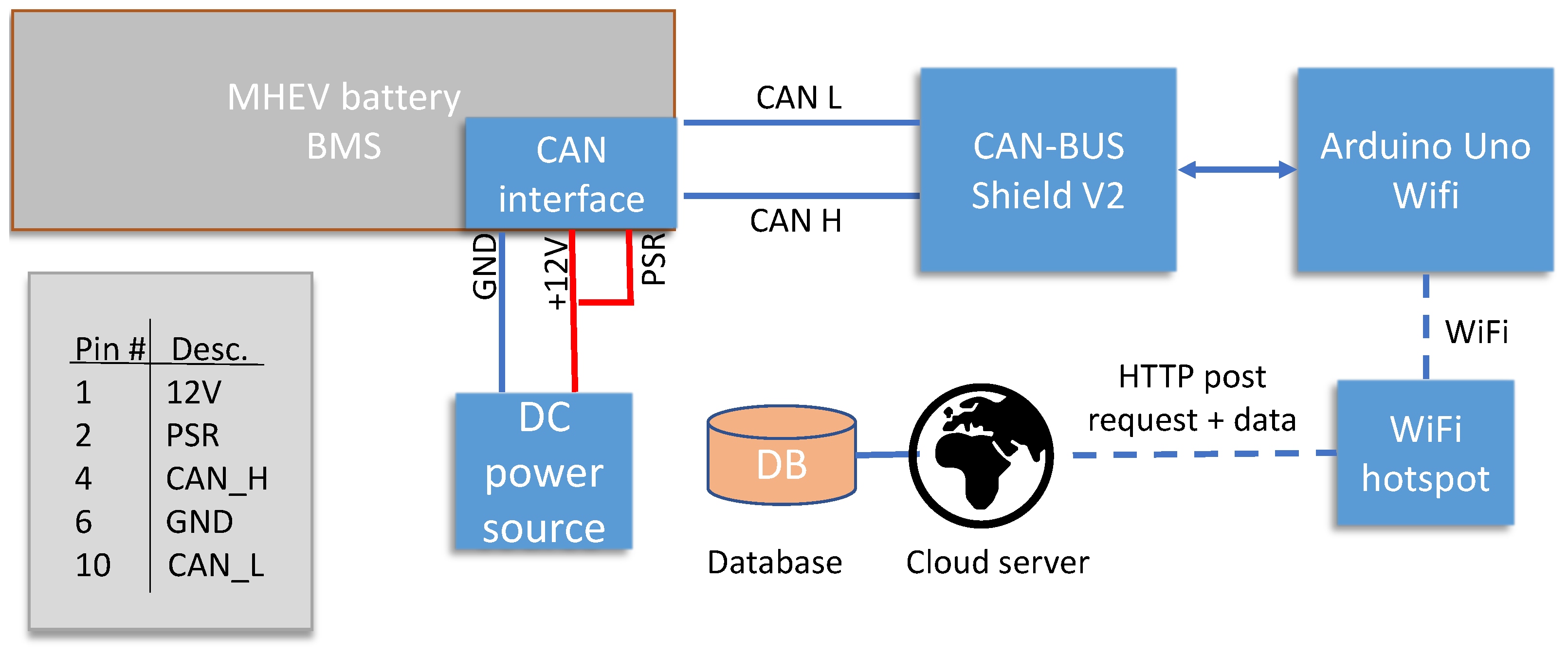
The CAN BUS Shield V2 module was installed on top of the Arduino Uno to interface the embedded system to the EVB. The Arduino connects to the computer via a USB cable to upload programs. The Wifi connection was configured to send the data to a cloud server database using a local network connection.
Figure 5 presents the end-to-end connection for data collection.
The CAN interfaces of the BMS and the embedded system were connected according to the wiring instructions provided by the EVB manufacturer. In addition to the CAN_H and CAN_L connections, it was necessary to supply an operating voltage to the 12 V and power sustain relay (PSR) pins of the BMS and a ground connection to the GND pin. The pinout of the EVB low voltage connector is presented in
Figure 5.
3.8. Data Collection and Uploading
For this study, an Arduino program capable of reading and sending CAN messages using the CAN shield and uploading the extracted data to a cloud server using WiFi was implemented using the C++ language. To enable the CAN shield, an additional library [
49] was installed in the Arduino IDE. The library provides functions to send and receive CAN frames and to configure the CAN interface parameters. The library was obtained from GitHub and installed in the Arduino IDE in zip format. Libraries mandatory to establish a WiFi connection and format the data for sending to the cloud server were also installed.
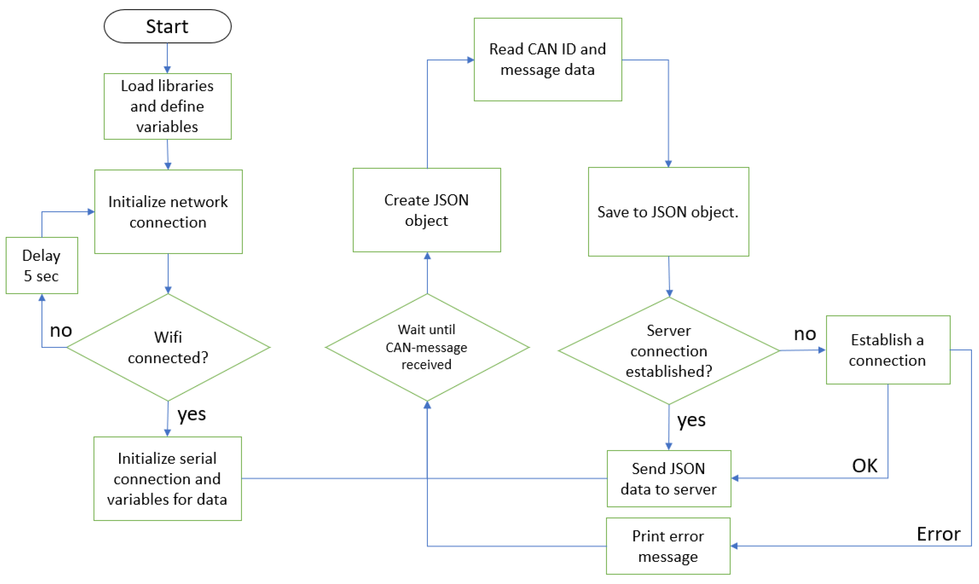
The implemented Arduino code establishes a connection to a WiFi network using the WiFi library, sets up a CAN communication interface using the Serial_CAN library, and then continuously reads CAN messages. When a CAN message is received, it will be stored in a JavaScript object notation (JSON) object and sent to the server for backup. The flowchart presented in
Figure 6 describes the code’s functionality.
The process begins by loading the required libraries and initializing the CAN interface connection. Required variables, such as SSID, password, and host, are declared.
The setup function will initialize the WiFi connection and reading of the CAN messages after the WiFi is connected. The WiFi loop itself continues until a successful connection is established. Inside the loop, there is a delay of five seconds between each attempt, and a message is printed to the serial monitor indicating the ongoing connection attempt. Once the connection is established, a message is printed to the serial monitor, and the board starts to read data from the CAN interface at a 500 k baud rate.
The loop function is another fundamental part of Arduino code, along with the setup function. A loop function in Arduino is designed to run continuously without an end call by default. In this research, an event handler is set up to monitor incoming CAN messages. Upon arrival, data are split into ID and 8 bytes of message and stored in appropriate variables for handling.
The loop continues by creating a JSON object and populating this array with values from the received CAN data array. Finally, data will be sent to the server using the sendToServer-function, which captures the data as a parameter and attempts to connect to a server using the client object. If the connection is successful, it sends an HTTP POST request with specific headers and the JSON data to the endpoint. After sending data successfully, it prints a confirmation message to the serial monitor and closes the connection. An error message is printed if a connection is not established and data cannot be sent to a server.
3.9. Identifying and Decoding the Temperature Message Identifier
The BMS is programmed to send several CAN messages periodically to indicate the status of the EVB. The periodic messages were collected and studied to find out the CAN message ID of the EVB cell temperature. Before the study, the battery was subjected to cold outdoor storage to enable a wide variation of the EVB temperature and ease the detection of a rising value in the periodic CAN messages. During the study, the battery temperature rose from temperatures as low as −24 °C to room temperature of 21 °C.
Throughout the 120-min test duration, CAN messages were continually monitored at intervals of 500 ms and relayed to the server for storage in the database. After a test sequence, 6005 CAN messages were recorded and stored in a database. Database query provides five distinct CAN IDs, listed in
Table 1.
Collected data were filtered with different CAN IDs, and by using the boxplot function, it is easy to notice which CAN ID message contains data that were changed during the test period. By tracking the changing data values over the test period, it was trivial to notice that CAN ID 588 contains temperature data. With the battery offline on the table, the status remains unchanged during this test except for the temperature. This value changed during the test, reflecting the EVB temperature transition from −24 °C to 21 °C.
The battery’s internal temperature raw CAN message values are extracted from the CAN ID 588 messages. The following formula extracts the first row of CAN data as an example. Because temperature is raised over the test period, all values are required to be deciphered individually.
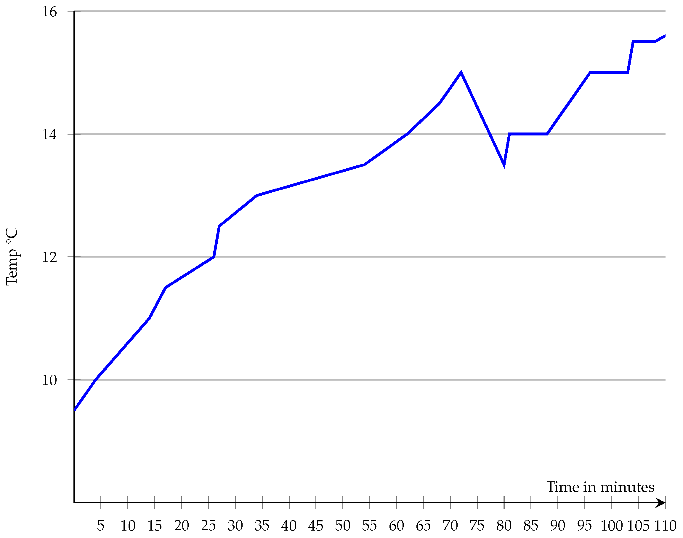
Figure 7 illustrates the plotted temperature values during battery acclimation to room temperature. An abnormal drop in the temperature values is seen in the histogram near minutes 70–95. The test did not involve external heating or altering a battery to a cold environment. Noticeably, the battery’s temperature continued to rise after this anomaly. At the end of the 120-min test period, the battery reached 16 °C in temperature.
A request to obtain the DBC file for EVB was sent to the manufacturer to decode the five cyclic CAN messages. While the manufacturer did not provide the complete DBC file describing all the CAN messages of the EVB, a DBC file describing the five cyclic messages and details for a CAN request to initiate the battery were shared to support our research.
3.10. Identifying and Decoding State of Charge and Voltage Message Identifiers
Bit operations are required to decode raw CAN message data. In case each data byte contains 8 bits, a total of 64 bits is extracted from each message. Bits can be ordered in two ways: Little Endian or Big Endian. This specific information can be obtained from the DBC file as shown in
Figure 8. Each message contains information related to bit ordering after @-symbol. @0 refers to big endian, and @1 refers to little endian.
Following data conversion into a bit sequence, segmentation occurs based on instructions outlined in the DBC file, which is succeeded by decimal conversion. The physical value is subsequently derived by multiplying the raw CAN value by the scale factor and incorporating any relevant offset in Equation (
1).
where
P is the physical value,
R is the raw value,
S is the scale factor, and
O is the offset. Using different scales, manufacturers can compress a broader range of values into a shorter sequence of bits, but this comes at the expense of precision. Because CAN IDs 589, 1085, and 587 did not provide valuable information for this research, those will be excluded from further examination. Finally, three intriguing CAN messages from IDs 588 and 122 were identified during charge and discharge cycles. These messages are then extracted and subjected to additional analysis in the following way:
Battery SoC, ID 588, bits 29–32
Battery voltage, ID 122, bits 17–29
Battery temperature, ID 588, bits 9–16
At first, SoC will be evaluated by analyzing CAN ID 588 bits as defined in the DBC file. Bits from 29 to 32 will be extracted, converted to decimal value, multiplied with scale, and added appropriate offset, respectively. As a result of these operations, an SoC of 6.81% was obtained, indicating a low battery charge.
The battery voltage can be obtained from the same CAN ID message 588, this time by extracting bits 17–24. Following the procedure, a voltage of 40 volts will be evaluated. This value matches the SoC for this 48 V EVB.
3.11. Battery Startup Procedure
The manufacturer provided a start-up routine for the EVB to initiate the battery for charging and discharging. The start-up procedure includes connecting additional +12 V and ground to the EVB main terminals. It is important to note that the 48 V terminal remains unconnected at the initiation stage. The 12 V connection provides the power to energize the isolation contactor, enabling battery connection to the main terminals. The position of the terminals can be seen in
Figure 4.
After the voltage connections, sending a CAN request message initiates the EVB. Using a request message provided by the battery manufacturer, the EVB was initiated. The message closes the isolation contactor, connects the 48 V to the battery terminals, and starts the battery.
The message ID to initiate the battery is 603. The message starts at bit 20 and has a length of 2 bits. The message accepts values between 0 and 3. According to CANdb++ [
53] analyzed DBC file, 0x00 represents ‘open’, 0x01 represents ‘close’, 0x02 represents ‘retain’, and 0x03 represents ‘undefined’. A message with the value 1 was sent to the BMS to initiate the EVB.
The message is located inside the data2 byte, which contains data bits 23–16, and the actual data to be sent consist of bits 19–20. Bit number 19 is set to 1, resulting in the appearance of data2 as 00001000 in bits, making the full CAN message.
After sending the request, a noticeable isolation contactor connecting sound can be heard from the battery pack, signaling the battery’s start-up. The battery’s voltage is now available on the 48 V terminal, and charging the battery can be initiated by connecting a power source to the battery terminals. Once the battery has reached the desired SoC, the charger or load is disconnected, and a CAN message filled with value 0 is sent to ID 603 to shut down the EVB. Alternatively, the EVB shuts down by disconnecting the 12 V power supply.
4. Results
The results of the charge, discharge, and overheat tests are presented in the following subsections. Each test lasted 110 min, and the results are presented as histograms. The test setup consists of the EVB, an embedded system, a 12-volt DC power source, and, depending on the test, either a 48-volt power source or a resistance load connected to the EVB output.
Figure 9 presents a functional diagram of the test setup.
4.1. Charging Test
After the battery start-up procedure, a 48 V power supply was connected to the EVB terminals to initiate the charging process. The charging current was limited to a maximum of 5 amperes to prevent damaging the battery by overcharging. CAN messages were recorded and stored in the database throughout the charging process for further analysis. At the onset of charging, the battery’s voltage was 40 V, and the target voltage was set to 48 V, equating to approximately 80% SoC.
After 100 min of charging, the battery voltage reached 48 V, and the charging current gradually decreased to zero. The stabilization phase lasted 10 min, resulting in a total charging time of 110 min. To complete the charging process safely, both the power supply and CAN interface were disconnected, which triggered the isolation contactor to open and the battery to return to an idle state. Finally, CAN messages were analyzed and converted to physical values, representing voltage, temperature, SoC, and current.
Previously ignored CAN message ID122 represents the battery’s current flow and became significant during the battery charging and discharging tests. Since that message was not decoded earlier.
It is also worth noting that when charging the battery, the BMS records the current as negative because the current flow is towards the battery. When the battery is in use, the current is positive.
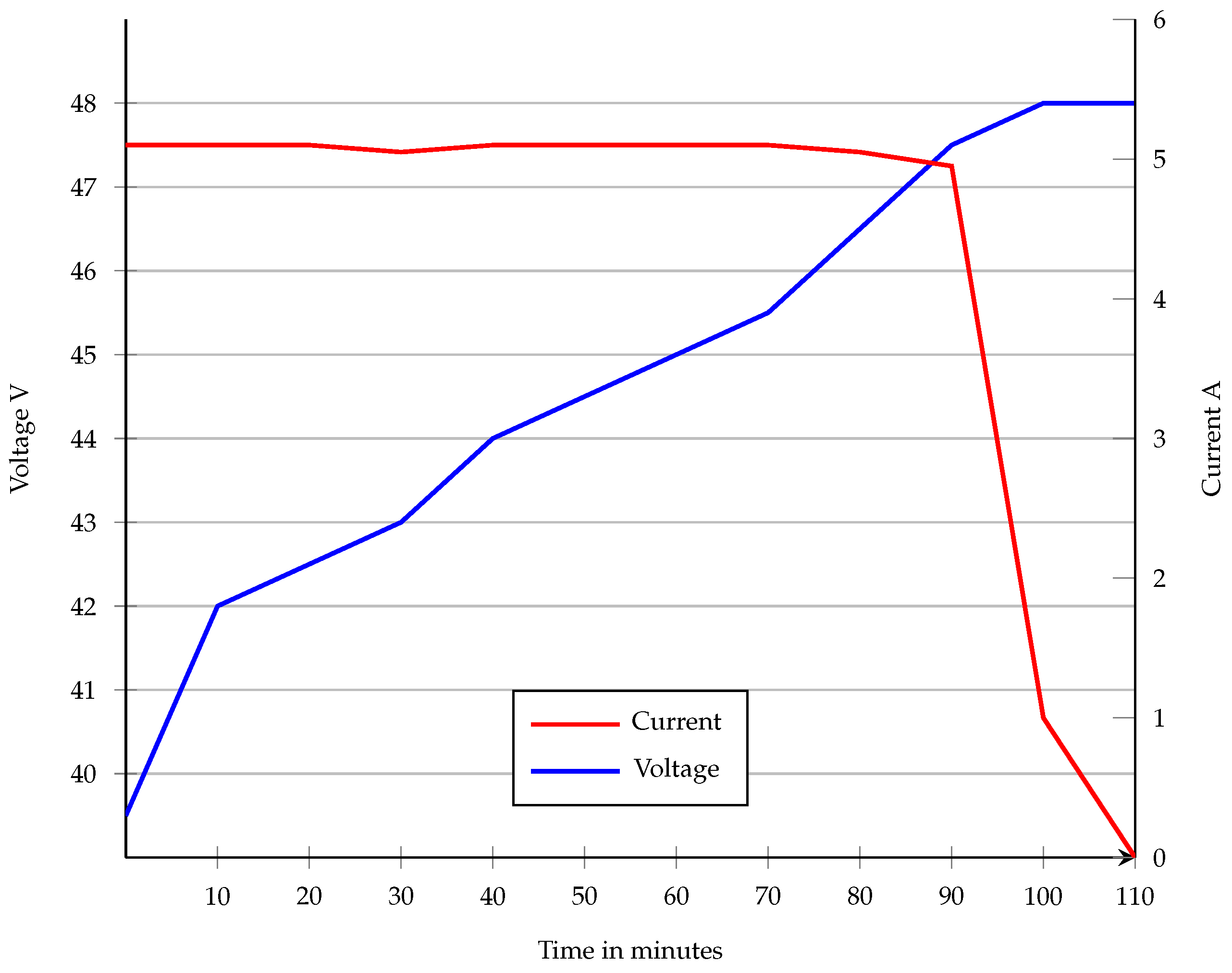
The charging current was set to a constant rate of approximately 5 amperes, while the charging voltage was adjusted according to the battery’s charge level. After about 100 min of charging, the battery reached the target voltage of 48 V, which decreased the charging current. Negative data values were converted to absolute values to improve human readability.
Figure 10 shows the current and voltage during the charging process. During the first ten minutes of charging, the battery’s voltage increased by 2 volts, but the rate of voltage incrementation slowed down eventually. Upon reaching its targeted voltage, the battery remained at that level, courtesy of the low charging current.
The data in
Figure 11 presents the battery’s internal temperature and SoC during charging. Before the test, the battery was located outside, and its onset temperature was 11.5 °C. During the 110-min test period, the temperature increased to 18 degrees Celsius. It is worth noting that there were some misreads of temperature sensors during the test, causing the temperature to drop suddenly without external cooling. This type of event also occurred in a previous test, as shown in
Figure 7, raising concerns about the reliability of the BMS temperature measurement.
The SoC values plotted in
Figure 11 are expressed in the precision of two decimals, rendering them highly precise. Storing this data with such accuracy requires 14 bits, as discussed earlier. Despite the high precision of the data, no deviations or errors were detected in the measurement of SoC data. Consequently, the battery’s SoC increases straightforwardly during the charging process, attributed to a constant fixed charging current of 5 amperes. After 90 min, the SoC level remains almost unchanged due to the low charging current.
The histograms in
Figure 12 represent the relationship between EVB voltage and SoC. The histogram can be utilized to estimate the battery SoC in the future by measuring the open circuit voltage of the battery pack using a standard multimeter. It is essential to note that this histogram only represents the behavior of this specific type of battery during one charging cycle and cannot be generalized to all 48 V batteries.
4.2. Discharge Test
Two adjustable power resistors with maximum adjustable resistances of 30 and 50 ohms were connected to the EVB in parallel to keep the discharge current at approximately 2.5 amperes and to enable altering the resistance during the test. CAN messages were collected and saved to the database throughout the discharge procedure for future analysis.
After 165 min of discharging, the battery voltage reached 42 V, corresponding to approximately 20% SoC. The test ended with sending a CAN request to the BMS to shut down the EVB. The received CAN messages were all analyzed following a procedure similar described in the charge test.
The discharging current during the test was set to 2.55 amperes. Over time, the current decreased due to the voltage drop resulting from the drainage of the battery. The power resistors converted this energy into heat, causing them to reach a temperature of approximately 50 °C during the test period.
While discharging, the battery experiences a voltage drop, initiating a decrease in SoC. As the voltage decreases, the current the EVB can supply decreases. Once the voltage reaches 42 Volts, the battery has lost most of its charge, and the discharge test can be terminated. The progression of voltage and current during the discharging process is shown in
Figure 13.
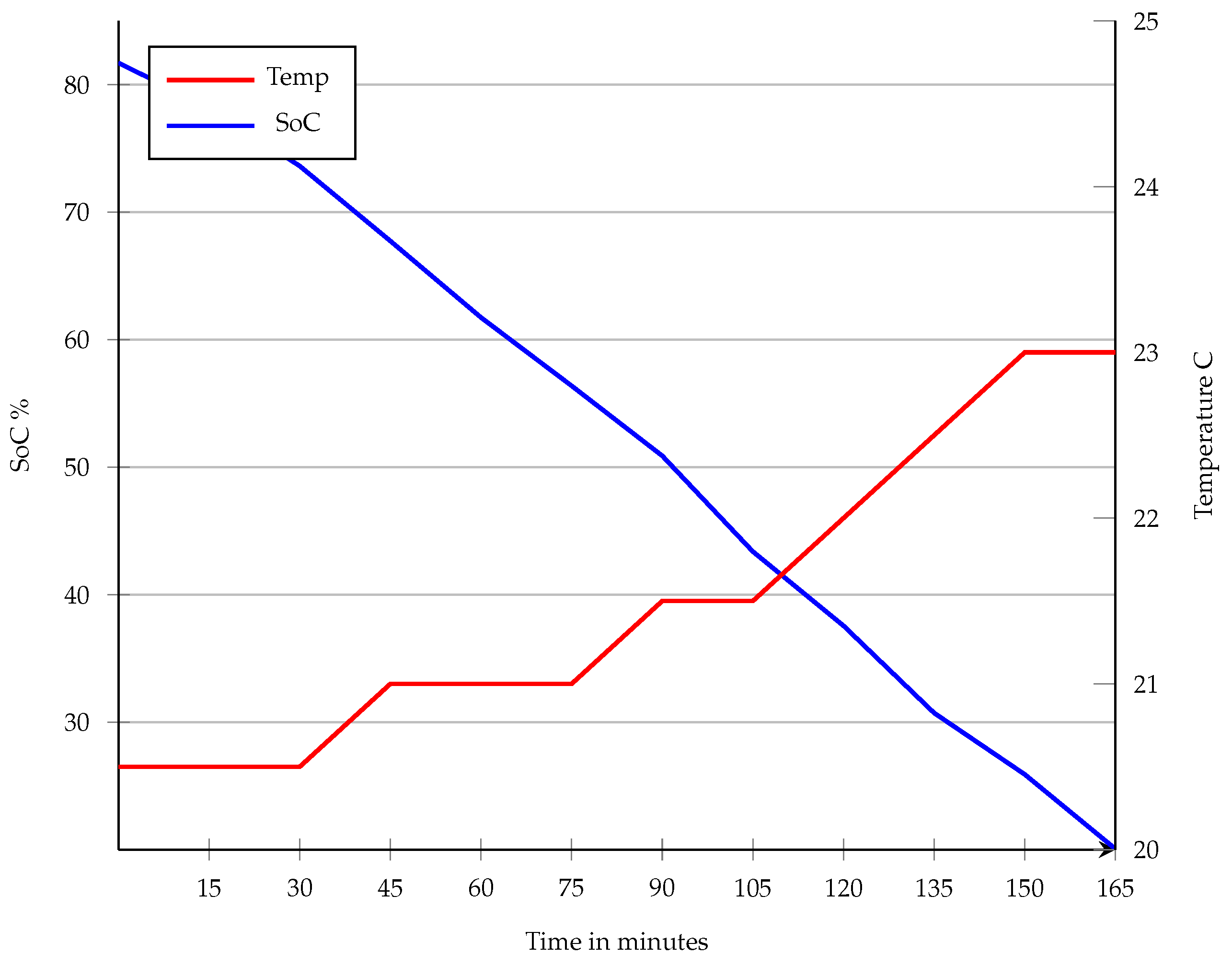
The temperature of the EVB rose by 2.5 degrees during the discharging test, as presented in
Figure 14, which is almost negligible. It is also worth noting that this test does not reveal any issues with temperature misreads of the BMS, suggesting that this problem may occur randomly or at relatively low temperatures only.
As the charging test states, the SoC level is represented in the precision of two decimals, rendering it an exact value to transmit via the CAN interface. When discharging a battery with a constant load, the SoC level decreases linearly, as depicted in
Figure 14.
4.3. Battery Overheat Test
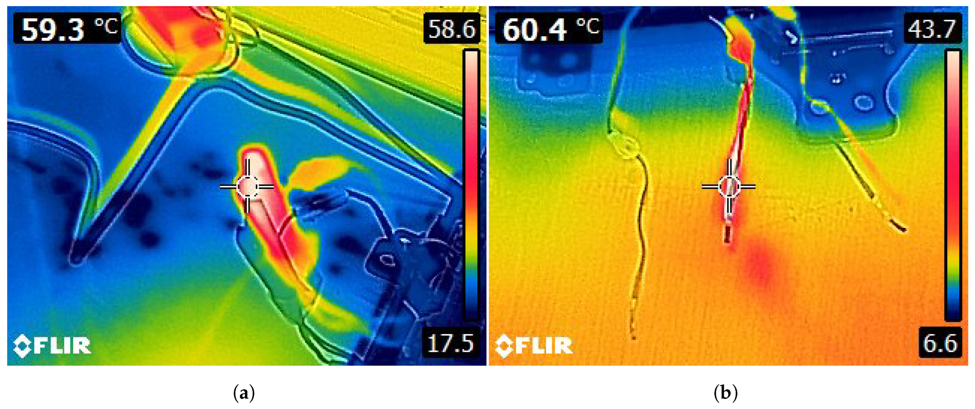
The following test investigates the efficiency of the EVB overheating protection mechanism through experimental analysis. The EVB was initiated, and all three temperature sensors
Figure 4 were grouped and subjected to external heating with a hot air gun while monitoring both CAN messages and sensor temperatures using a handheld thermal camera illustrated in
Figure 15a.
Upon reaching a critical temperature threshold of 60 °C, indicative of potential overheating, the battery’s protection mechanism was observed to trigger, resulting in the opening of the isolation contactor to prevent further thermal escalation.
Furthermore, the data byte 3 value in CAN ID 588 changed from 8 to 136, where bit number 31 represents 0 (8) and 1 (136). This change signifies an overheating condition and triggers the thermal management system to operate. Once the temperature decreased below 60 °C, the value reverted to 8, indicating that cooling was no longer necessary. The temperature data obtained from the CAN interface during the experiment are presented and analyzed in
Figure 16.
After the battery temperature decreased to a safe level and no longer required cooling, the isolation contactor failed to close automatically. This prevented the battery from being used for charging or discharging. To re-initiate the battery, the startup procedure had to be repeated.
Additionally, another overheat test was conducted. Each temperature sensor was individually heated to determine how the BMS would react if one sensor overheated while others remained at average temperatures. The test showed that the BMS treats the three sensors as a single unit, calculating the average temperature of all three sensors. The test did not trigger an overheat warning when heating just one of the sensors as shown in
Figure 15b. Based on the test results, a concern was raised regarding the placement of sensors inside the battery, which can be seen in
Figure 4, which could lead the BMS to react to the thermal runaway of one of the pouch cells.
5. Discussion
Integrating CAN data analysis into the recycling process of lithium-ion batteries can streamline the EVB testing procedures for efficient recycling and repurposing practices. Harnessing the CAN interface enables the assessment of various EVB health and safety-related data, contributing to informed decision-making from testing to reuse and recycling. The following subsections discuss the results of this study and the feasibility of utilizing the CAN interface and BMS in the recycling process.
5.1. The Feasibility of Utilizing BMS Data in the EVB Processing
The reliability of the data extracted using the CAN interface depends on the integrity of the BMS hardware and software. The internal algorithms the BMS utilized to define the SoC, cell temperatures, and the SoH of the EVBs are currently proprietary information. Besides the BMS software, the design details of the EVB hardware are disclosed information. In this study’s case of the MHEV battery, the average temperature measurement of the three temperature sensors is not a reliable way to detect a thermal runaway. The temperature rise of a single sensor at room temperature must exceed 138 °C to trigger an average value of 60 °C. If thermal runaway occurs in one of the cells without temperature sensors, the temperature required is even higher.
The cell temperature reading anomaly presented in
Section 3.9 during the temperature test proves the inaccuracy of the BMS sensing hardware or software and questions the reliability of temperature data extracted from the BMS. The cyclic time for sending the cell temperature to the CAN interface is ten seconds, which is too infrequent for safety monitoring.
Currently, the CAN interface and BMS are designed for automotive applications and do not provide fast and accurate data to detect thermal runaway in a reasonable time to trigger fire safety functions. Detecting thermal runaways to trigger fire prevention requires reliable monitoring and fast anomaly detection, making the BMS unsuitable as the primary method for monitoring safety during dismantling. The BMS data can be used as a secondary method to increase safety by detecting sudden voltage dips or current flows during the dismantling.
The BMS data are not feasible for safety purposes. The BMS and the integrated sensors are feasible for charging or discharging the EVB to the ideal SoC level for storage before the dismantling. Monitoring EVB voltage and current during charging processes enables the detection of anomalies indicating potential safety issues, such as overcharging or undercharging. Additionally, real-time SoC monitoring enables precise charging level management, maximizing battery longevity. Similarly, monitoring critical parameters during discharge cycles ensures safe and optimal battery power utilization. It is also feasible to utilize the BMS and CAN interface to monitor EVB parameters during long-term storage. Before disassembling the EVBs for repurposing, ensuring the correct charging level of the modules for storage is essential. An ideal SoC level during storage ensures battery degradation is avoided during long-term storage.
5.2. The Effect of the Proprietary Nature of Specifications for Utilizing the CAN Interface
The data, encompassing voltage, current, temperature, and SoC, were collected from the BMS using the CAN interface. Despite multiple attempts, the authors could not extract the SoH of the EVB. During comprehensive testing, the BMS did not output a CAN message containing the SoH value. Most likely, sending a request message to a specific ID is required to assess the SoH information. The authors’ efforts were hindered by the lack of a complete DBC file to decode all the CAN messages. The EVB battery manufacturer provided limited information to decode the five CAN IDs presented in
Section 3.9 and the request message to initiate the EVB.
The absence of DBC files from EVB manufacturers complicates utilizing BMS data during recycling and repurposing. While these methods offer potential solutions, collaboration with manufacturers to obtain DBC files remains the most effective approach to streamline data analysis and ensure accuracy in message interpretation. For this study, the EVB manufacturer provided information to decode the five cyclic CAN messages and the structure of the CAN request to initiate the EVB. Access to a complete DBC file containing all the CAN messages would have enabled a more comprehensive study of the RUL and SoH of the EVB.
5.3. Future Work
The presented embedded system prototype could be developed into a completely wireless system. A mobile location-independent BMS data collection device operating on battery power would be feasible for the EVB recyclers. A portable device connecting to the EVB CAN interface to upload the crucial data to a cloud server for further evaluation is an essential tool in the sorting phase of EVBs. For instance, the portable solution could find applications in battery storage facilities to monitor the warehoused EVB by periodically sending information to a cloud server.
This setup would enable situational monitoring during battery storage, improving overall safety. Moreover, defining alarm triggers would improve safety while storing the EVBs; for example, if the battery temperature reaches a critical high, the system would trigger an alarm.
The same remotely operated technology could also enhance the safe transportation of batteries. Connecting a remote CAN monitoring device to the EVB enables real-time monitoring during transport. This strategy would facilitate the timely identification of anomalies, enabling proactive measures to be taken to ensure the safety of the EVB, driver, vehicle, and the environment during transportation.
The server data analysis can be enhanced by integrating the portable CAN interface device, which includes decoding the CAN messages based on a DBC file on the server and implementing automatic bit-wise operations for data decoding. Additionally, the system’s agility can be improved by developing methods for remote modification of the server- side code.
A potential area for future research involves developing a portable system that will enable remote utilization of the CAN message reading system. Such a setup could find application in battery storage facilities, allowing remote monitoring and enhancing overall safety. Additionally, improving server-side data analysis capabilities, including DBC file-based interpretation of CAN message data, could enhance the system’s efficiency and adaptability. With continued research and development, using the battery’s CAN data in recycling holds promise for further revolutionizing battery management and recycling practices.
6. Conclusions
An approach to assess the health and risk of EVBs using an embedded system to extract the required data from the BMS via the common automotive CAN interface was presented. The embedded system enables recycling companies to evaluate the risk, health, and charge level of EVBs before recycling, repurposing, and storage. We obtained voltage, current, SoC, and temperature parameters from the BMS during this study. The temperature values were only sometimes accurate, with the value representing an average of three sensors, and there were also occurrences of misreads within the sensor data. This, along with the slow message-transmitting cycle, raises concerns about using temperature data for real-time thermal runaway detection.
The disclosed nature of the DBC files to decode the CAN messages complicates extracting the data, controlling the EVB during the assessment, and ensuring optimal SoC for storage. In the future, the stakeholders of the EVB recycling industry will benefit from having access to the complete DBC files to decode the CAN messages. Opening the software and hardware designs of the BMS implementations enables the evaluation of the reliability of the data provided by the BMS. As the regulations guide the industry, the EU battery passport could oblige EVB manufacturers to include DBC files or the CAN message decoding information. This has the potential to act as a catalyst for sharing this information. Additionally, releasing the BMS hardware and software design information regarding the temperature and overcharging monitoring would benefit the stakeholders of EVB recycling.


