Abstract
Recent advancements in energy conversion and storage systems have placed a spotlight on the role of multi-functional electrodes employing conductive substrates. These substrates, however, often face obstacles due to intricate and expensive production methods, as well as limitations in thickness. This research introduces a novel, economical approach using graphite felt as a versatile electrode. A method to enhance the typically low conductivity of graphite felt was devised, incorporating interfacial chemical tuning and the electrodeposition of a highly conductive nickel layer. This technique facilitates the integration of diverse transition metal-based active sites, aiming to refine the catalytic activity for specific electrochemical reactions. A key finding is that a combination of a nickel-rich cathode and an iron-rich anode can effectively optimize alkaline water electrolysis for hydrogen production at the ampere scale. Furthermore, the addition of sulfur improves the bi-functional oxygen-related redox reactions, rendering it ideal for air cathodes in solid-state zinc–air batteries. The assembled battery exhibits impressive performance, including a peak power density of 62.9 mW cm−2, a minimal voltage gap in discharge–charge polarization, and a lifecycle surpassing 70 h. This advancement in electrode technology signifies a significant leap in energy storage and conversion, offering a sustainable and efficient solution for future energy systems.
1. Introduction
The progress in sustainable energy technologies is largely dependent on the efficiency of crucial components such as electrodes, especially in applications such as ampere-scale alkaline water electrolysis [1] and zinc–air batteries (ZABs) [2]. Despite significant advances in understanding intrinsic catalytic activity [3,4], the selection of current collecting materials remains largely limited to a few commercialized options. In hydrogen production through alkaline water electrolysis, nickel foam is a popular choice due to its excellent electrical conductivity and structural characteristics. Nevertheless, there is an active pursuit for alternative materials that can offer comparable or superior performance at reduced costs. Regarding battery technology, zinc–air batteries are noted for their high energy density and eco-friendliness. The air cathodes in these batteries, commonly made from carbon nanofiber paper or carbon cloth, also serve as typical gas diffusion layers (GDL). Despite offering favorable electrical conductivity and structural advantages, these materials have a limitation: their thickness is usually less than 1 mm, which can hinder their performance and limit their application possibilities.
Graphite felt (GF) stands out as an ideal, versatile electrode material [5], particularly for flow-type batteries [6]. GF is significantly more affordable than nickel foam and other carbon-based alternatives, costing approximately USD 3-4 for a 100 × 100 mm piece with 5 mm thickness. The cost-effectiveness of GF, along with its mechanical and structural qualities, makes it a promising candidate for further research and development in electrode technology. Consequently, GF has seen application in research areas such as water electrolysis and ZABs. Its highly porous structure offers substantial benefits over the denser compositions of carbon nanofiber paper and carbon cloth, leading to high potential in both alkaline water electrolysis and ZABs. In water electrolysis, the use of GF is due to its ability to support catalytic materials, contributing to hydrogen evolution reaction (HER) [7], oxygen evolution reaction (OER) [8], and overall water-splitting (OWS) processes [9]. However, its performance is not necessarily superior compared to more conductive materials. Similarly, the large surface area and porous nature of GF are advantageous for facilitating reactions such as oxygen reduction (ORR) and OER, crucial for ZAB operation. The porosity of GF plays a crucial role in promoting gas diffusion in air cathodes and supporting catalytic materials within large 3D reaction areas. However, the utilization of GF in ZABs is rarely reported [10,11], and these batteries primarily relate to their structural properties rather than their conductivity. It is essential to recognize that while GF offers certain advantages, its performance in terms of conductivity does not necessarily match that of the more conductive materials used in these fields. The relatively lower electrical conductivity, leading to higher ohmic losses in electrochemical systems, remains a challenge. Addressing and implementing strategies to enhance the performance of GF, to rival or surpass that of conventional materials, is crucial. In this context, our work focuses on enhancing the electrochemical activity and conductivity of GF through innovative modifications, thus paving the way for its practical application in efficient energy conversion and storage systems.
The process of electrodeposition, or electroplating, presents significant benefits for the even application of active materials onto substrates [12,13], including graphite felt, when contrasted with the conventional powdery casting method. The powdery casting technique often leads to a non-uniform catalyst layer and struggles to penetrate deeply into the porous structure of graphite felt. This inconsistency and limited penetration can negatively impact the efficiency and effectiveness of the air cathode in electrochemical applications. Conversely, electroplating offers a more suitable solution for porous materials like graphite felt. Recent studies have shown that Ni electroplating using a Watt bath significantly enhances the electronic conductivity of carbon-based electrodes [14]. The electrodeposition process enables a uniform and precise layer of active materials to be directly grown on the substrate. This method ensures that the active materials thoroughly permeate the complex porous network of the graphite felt, optimizing the active surface area for electrochemical reactions. Such uniform coating is crucial in improving the catalytic activity, efficiency, and longevity of the air cathode, especially in the challenging environments of solid-state ZABs. This approach not only elevates the performance of the electrode but also supports the advancement of manufacturing techniques in the development of high-performance electrodes for next-generation electrochemical devices.
In this research, an efficient Ni electroplating method is introduced to utilize low-cost yet highly porous graphite felt as versatile electrodes for alkaline water electrolysis and ZABs. Before the Ni electroplating, the naturally hydrophobic graphite felt undergoes functionalization through acid and amine treatments. These treatments enhance the introduction of transition metal precursors and improve electrochemical reaction efficiency in aqueous media. As a result, significantly improved electrical conductivity is achieved, along with the generation of nickel-rich sites. These sites are conducive to the selective addition of other elements like iron (Fe), manganese (Mn), and sulfur. For example, Ni-plated GF demonstrates high hydrogen evolution reaction (HER) activity, whereas the highest oxygen evolution reaction (OER) activity is observed in Fe-introduced Ni-electroplated GF samples, and the two can be coupled for an efficient overall water-splitting system. This GF-based water electrolysis system requires only 1.60 V to produce a current density of 20 mAcm−2, and ambient-condition ampere-scale hydrogen production can be obtained at 2.3 V to produce a current density of 1.0 A cm−2. Additionally, the successive introduction of Mn and S in Ni electroplated GF leads to high bi-functional activity toward oxygen-related redox reactions. A solid-state zinc–air battery assembled using this air cathode, combined with zinc foil and a dough-type sodium alginate–KOH electrolyte, exhibits a relatively high peak power density of 62.9 mW cm−2. It also demonstrates a low voltage gap between discharge and charge polarization and a cyclic lifetime exceeding 70 h.
2. Experimental Section
2.1. Fabrication of Nickel-Electroplated Graphite Felt Electrodes
Graphite felt (GF) underwent a surface treatment process involving a potent acid mixture composed of equal volumes of H2SO4 and HNO3 and maintained at 70 °C for 12 h. Following this, the acid-treated GF was thoroughly rinsed with deionized water. Next, the GF was submerged in a tris (2-aminoethyl)amine solution (concentration of 5 mg mL−1 in ethanol) at ambient temperature for three hours, resulting in acid- and amine-treated GF (AA-GF). The resulting AA-GF was then subjected to electrodeposition using a power supply and a Watt bath electrolyte solution. This solution contained 0.913 M NiSO4 6H2O, 0.189 M NiCl2 6H2O and 0.485 M H3BO3. In this setup, the AA-GF served as the cathode and a nickel plate as the anode. Typically, a voltage of 4.0 V was applied for a duration of 10 min to fabricate GF@Ni electrodes. Finally, the electrodeposited sample was washed in deionized water and allowed to dry at room temperature.
2.2. Fabrication of Ni-M (M = Fe or Mn) and Ni-Mn-S Active Electrodes
For depositing Fe or Mn layers onto GF@Ni samples, a specific electrodeposition process was employed. This involved using a power supply with either 0.1 M Fe(NO3)3 9H2O or 0.1 M Mn(SO4) 5H2O aqueous solutions as the electrolyte. In this configuration, a Ni plate was used as the anode and GF@Ni as the cathode. A current density of 30 mA cm−2 was applied for 10 min to achieve a targeted loading of 2 mg cm−1 of M (where M = Fe or Mn). Subsequently, the samples were rinsed with deionized water and dried at room temperature. For the synthesis of GF@Ni-MnS, the prepared GF@Ni-Mn and 1 g of sulfur powder were positioned in separate alumina crucibles, approximately 1 cm apart. The components were then subjected to a sulfurization process in a tubular furnace. This was performed at a temperature of 450 °C, increasing at a rate of 5 °C per minute, under a flow of argon gas. The GF@Ni-MnS was obtained after it naturally cooled down to room temperature.
2.3. Structural and Compositional Analyses
The structure and nano-features of the developed samples were rigorously examined using a field-emission scanning electron microscope (S-4800 model, Hitachi, Japan). X-ray diffraction (XRD) studies, conducted with an X’Pert PRO diffractometer, were utilized to ascertain the crystalline structures of these samples. Additionally, X-ray photoelectron spectroscopy (XPS) was performed with a K-ALPHA system (by Thermo Fisher Scientific, Waltham, Massachusetts, WA, USA) to delve into the electronic structure and chemical states. The XPS measurements were specifically focused on the central region of the sample, as the edges tend to be more susceptible to enhanced deposition effects. A universal mechanical testing machine (UTM, AGS-X model, Shimadzu, Japan) was employed for the strain–stress test, operating at a speed of 10 mm per minute.
2.4. Electrochemical Performance Evaluation
Electrochemical properties were assessed using a dual-channel electrochemical workstation (ZIVE BP2A model, produced by WONATECH, Seoul, Republic of Korea). For the measurements of all electrochemical performances, the working electrodes were cut into the desired size of 1 × 2 cm−2 with a razor blade, and the exposed area of 1 × 1 cm² was controlled by masking the rest with polymer glue. To evaluate the catalytic efficiency for HER and OER, experiments were conducted in a 1 M KOH solution using a three-electrode system. In this setup, electrodes based on GFs served as the working electrodes. A mercury-mercury oxide electrode, filled with 1 M NaOH solution, acted as the reference electrode, and a graphite rod was used as the counter electrode. The potential versus Hg/HgO was converted to that versus reversible hydrogen electrode (RHE) by using the following equation [15]:
The HER catalytic activity was evaluated by linear sweep voltammetry (LSV) curves at a scan rate of 0.5 mV s−1 in 1 M KOH electrolyte with 90% IR correction. The resistance at high-frequency region (RHFR) value for iR-correction was obtained from a Nyquist plot, which was carried out at a current density of −0.1 mA cm−2. To prevent the overestimation of OER catalytic activity due to the overlapped redox reaction of transition metal species, the backward-direction LSV measurement was recorded at a scan rate of 0.5 mV s−1. Nyquist plots were obtained from electrochemical impedance spectroscopy (EIS) within a frequency range of 1 MHz to 0.1 Hz, with an amplitude disturbance set at 5 mV. The catalytic activity for the oxygen reduction reaction (ORR) was tested in an O2-saturated 1 M KOH solution using a three-electrode configuration.
2.5. Assembly of Solid-State Zinc–Air Batteries
The solid--state dough--type electrolyte was synthesized following established procedures in the literature [16]. This involved blending sodium alginate, KOH, poly (vinyl alcohol), and poly (acrylic acid). The assembly of the solid--state ZABs incorporated zinc foil as the anode. The solid-state electrolyte was made from the dough-type polymer mixture, and GF-based electrodes were used as the air cathodes. To regulate the exposed area of the air cathode, a rubber mold featuring a punched hole 1.1 cm in diameter was used, resulting in an exposed area of approximately 0.95 cm². Charge–discharge voltage profiles were recorded using a multichannel battery testing system (WBCS3000 model, WONATECH, Seoul, Republic of Korea) operating in galvanostatic mode. Cycling tests were conducted with each cycle lasting 40 min, divided into 20 min charge and discharge periods, at a current density of 5 mA cm−2.
3. Results
3.1. Surface Modification and Sequential Electroplating and Electrodeposition on Graphite Felt
The synthesis process used in this study is detailed in Figure 1. It begins with treating GF electrodes to increase their hydrophilicity, resulting in amine- and acid-treated GF (hereafter referred to as AA-GF). The treatment process includes an acid bath in a 1:1 mixture of H2SO4 and HNO3 at 70 °C for 12 h, followed by amine functionalization at room temperature for 3 h. Initially, GF displays hydrophobic properties, as seen by its tendency to float on water (Figure S1a), and after treatment, the electrodes exhibit enhanced hydrophilicity, allowing complete immersion in water (Figure S1b). This alteration in surface characteristics is confirmed via water contact angle tests. Untreated GF shows a distinct water droplet shape on its surface (Figure 2a), illustrating its hydrophobic nature and poor water absorption. In contrast, on AA-GF, water spreads more readily (Figure 2b), indicating better hydrophilicity and absorption. Following surface modification, nickel (Ni) electroplating is carried out using a Watt bath solution for the electrolyte, with a Ni plate as the anode and AA-GF as the cathode. A steady voltage of 4.0 V is applied for 10 min. Figure S2 illustrates the nickel electroplating on graphite felt samples at 4.0 V under different conditions, including untreated GF for 10 min (Figure S2a,b), AA-GF for 10 min (referred to as GF@Ni, Figure S2c,d), and AA-GF for 20 min (Figure S2e,f). Each sample exhibits a uniform Ni layer on the graphite felt, with electroplating on untreated GF causing some cracks. The HER activities of these samples were initially evaluated, as shown in LSV curves in Figure S3. The optimal HER activity is observed with GF@Ni for a 10 min electroplating period. Longer electroplating times do not yield significant improvements in terms of HER activity. Conversely, electroplating on untreated GF results in markedly lower HER activity, highlighting the crucial role of favorable interfacial interactions between GF and the Ni layer. Digital microscope images in Figure 2c display the color and morphological changes in GF-based electrodes. The highly porous structure of AA-GF, initially black, turns metallic silver with thicker microfibers after Ni electroplating for GF@Ni. Introducing Fe to GF@Ni-Fe and Mn to GF@Ni-Mn results in a brownish color change, with the fibrous matrices well preserved. FE-SEM images in Figure 2d,e show the interconnected fibrous structure of overall GF@Ni, with fiber surfaces appearing relatively smooth. A high-magnification SEM image in Figure 2f, post-nickel electroplating, reveals nickel crystal formation on the graphite felt fibers, confirming successful metal deposition. The fibers maintain their structural integrity after additional electrodeposition of iron (Figure S4a) and manganese (Figure S4b) layers. Both Fe- (Figure 2g,h) and Mn- (Figure 2i–k) coated samples show the development of densely packed nanosheet-like structures on the fiber surfaces.
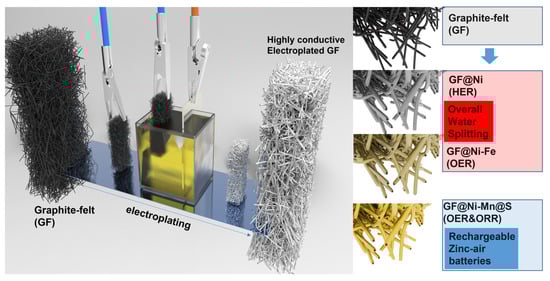
Figure 1.
Schematic illustration of the electroplating process for graphite felt, including customized subsequent treatments such as electrodeposition of Fe or Mn for GF@Ni-Fe or GF@Ni-Mn, respectively, and the sulfurization process for the creation of Ni-Mn@S active sites.
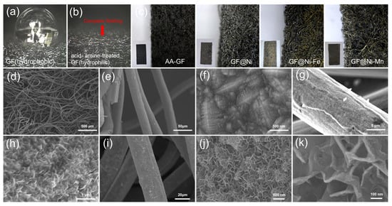
Figure 2.
Photograph images (a) showing a water droplet retaining its shape on an untreated graphene felt (GF) surface and (b) water absorption on the surface of acid- and amine-functionalized GF. (c) A series of digital microscope images, presented from left to right, depicting GF, GF@Ni, GF@Ni-Fe, and GF@Ni-Mn. Inset images provide detailed photographic views of each corresponding sample. (d–f) FE-SEM images displaying GF@Ni, (g,h) GF@Ni-Fe, and (i–k) GF@Ni-Mn.
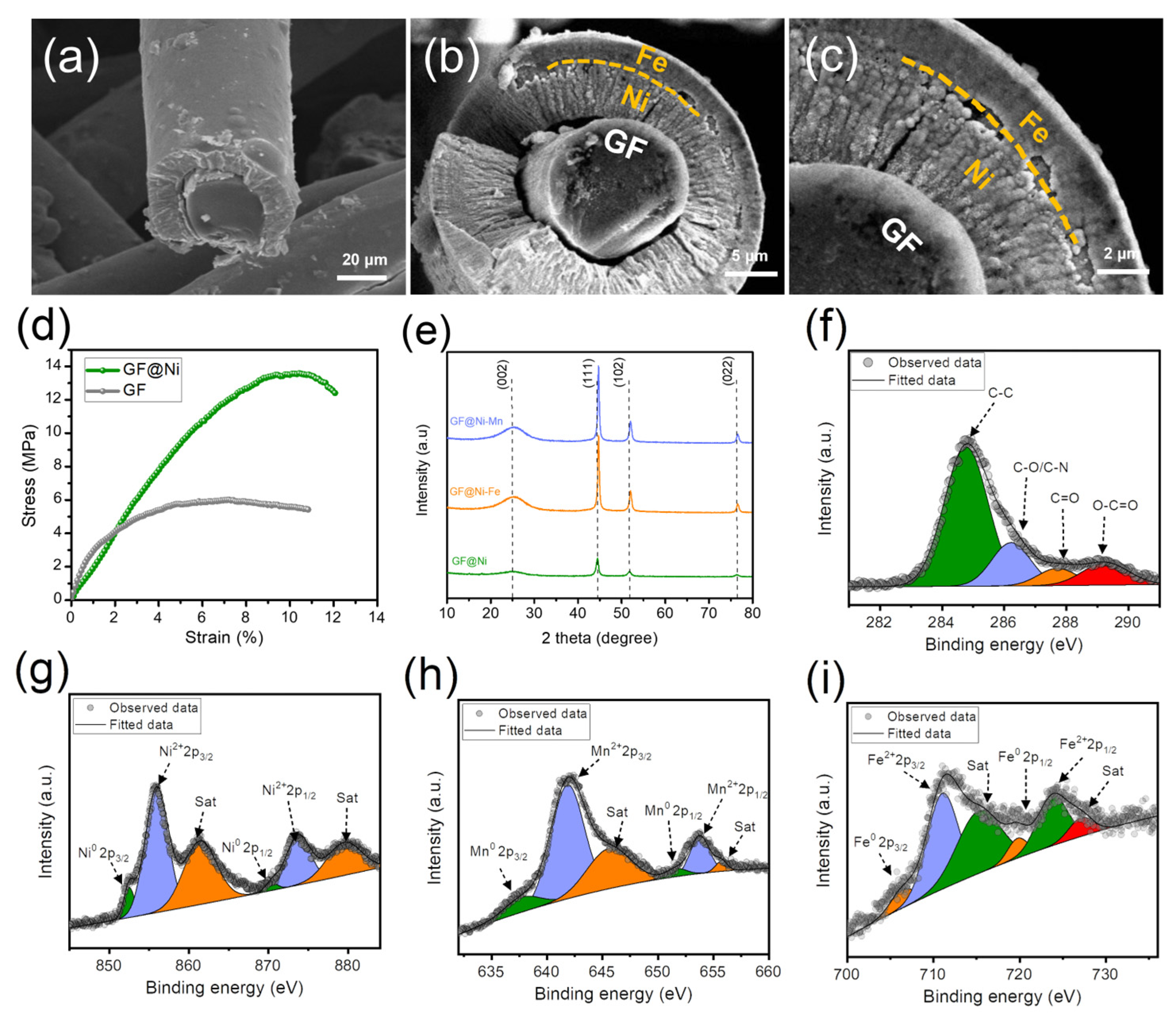
Figure 3a illustrates a cross-sectional SEM view of the GF@Ni microfiber, showcasing the one-dimensional electroplated Ni layer adhering to the solid carbon microfiber core. In Figure 3b, the GF@Ni-Fe microfiber displays a clear carbon microfiber core enveloped by a uniform nickel layer, which is further coated with an Fe layer. This uniform Ni coating, adhering to the fibrous matrices, along with the outer Fe layer, is crucial for boosting the efficient charge transfer in an electrocatalytic electrode. The granular structure of the Fe layer, firmly attached to the nickel-plated carbon fiber, forms a core–shell configuration that is both structurally robust and conducive to optimal charge transfer. Figure 3c provides an in-depth observation of this core–shell structure in the GF@Ni-Fe microfiber, where the Fe layer is evenly distributed over the nickel layer, enhancing the fibrous matrix. At higher magnifications, the densely packed microstructures of the Fe coating offer a broad, multifaceted surface, increasing the availability of active sites for electrochemical reactions. The integrity in one-dimensional fibrous matrices by coupling electroplated Ni-Fe multi-layers with carbon microfiber is anticipated to synergistically improve the electrical conductivity and charge transfer efficiency. These attributes are essential for optimizing the performance of these electrodes in electrochemical applications, surpassing traditional flat-layered electrode designs that feature two-dimensional planar catalyst layers. Similarly, SEM images from Figure S5a–d of GF@Ni-Mn indicate the presence of a carbon microfiber core encased by Ni and Mn layers. As depicted in Figure 3d, nickel electroplating significantly improves the tensile strength of graphite felt. The GF@Ni sample endures stress above 13.58 MPa with a strain exceeding 10.4%, significantly outperforming AA-GF, which holds up to 5.98 MPa at 6.0% strain. Figure 3e reveals the XRD patterns of GF@Ni, GF@Ni-Fe, and GF@Ni-Mn. All samples display similar XRD patterns with a notable peak at approximately 25.6°, corresponding to standard graphitic carbon (JCPDS card No. 26-107) and other significant peaks related to metallic nickel (JCPDS card No. 70-1849), without additional peaks. These findings suggest that either the relative intensity of Fe or Mn-OH is weaker than the prominent metallic Ni peaks [17], or there could be the formation of an amorphous metal (oxy)hydroxide phase [18]. Additionally, the metallic Ni peaks in GF@Ni exhibit a slight shift to higher angles upon the introduction of Fe or Mn, potentially due to the integration of these elements into the nickel lattice, altering its structural parameters [19]. Figure 3f represents the XPS fine C1s spectrum of AA-GF, verifying the presence of overlapping C-O and C-N bonds around 286.2 eV due to their similar electronegativities, along with distinct peaks for C-C (284.8 eV), C=O (287.8 eV), and O-C=O bonds (289.1 eV) [14,20]. The high-resolution Ni2p spectrum, presented in Figure 3g, exhibits a distinct zero-valence Ni peak at around 853.8 eV, accompanied by a notable peak near 855.8 eV, indicative of the oxidized state of Ni2+. Figure S6 features the fine O1s spectrum of GF@Ni, emphasizing the existence of M-O and M-OH chemical states, pointing to a high oxidation state of the electroplated Ni. Figure 3h and Figure 3i demonstrate the high-resolution spectra of Mn 2p and Fe 2p in GF@Ni-Mn and GF@Ni-Fe, respectively. In these samples, the absence of metallic zero-valence peaks confirms the relatively high oxidation states of the added Mn and Fe layers, consistent with Mn2+ to Mn4+ [21,22] and Fe2+ and Fe3+ [23,24,25] oxidation states. The fine C1s and O1s spectra of GF@Ni-Mn (Figure S7a,b) and GF@Ni-Fe (Figure S8a,b) show similar peak patterns, indicating the high consistency and reproducibility of the successive electroplating and electrodeposition procedures.
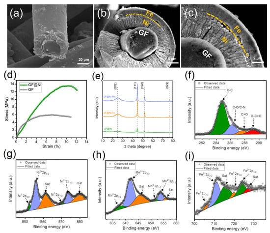
Figure 3.
FE-SEM images of the cross-sections of (a) GF@Ni and (b,c) GF@Ni-Fe cut using an ultrasonic cutter, showing the detailed microstructures. (d) Strain–stress curves of GF and GF@Ni using UTM, (e) XRD patterns of GF@Ni, GF@Ni-Fe, and GF@Ni-Mn. (f) XPS fine C1s spectrum of AA-GF, (g) fine Ni2p of GF@Ni, (h) Mn2p of GF@Ni-Mn, and (i) Fe2p spectrum of GF@Ni-Fe.
3.2. Electrochemical Evaluation of GF-Based Electrodes
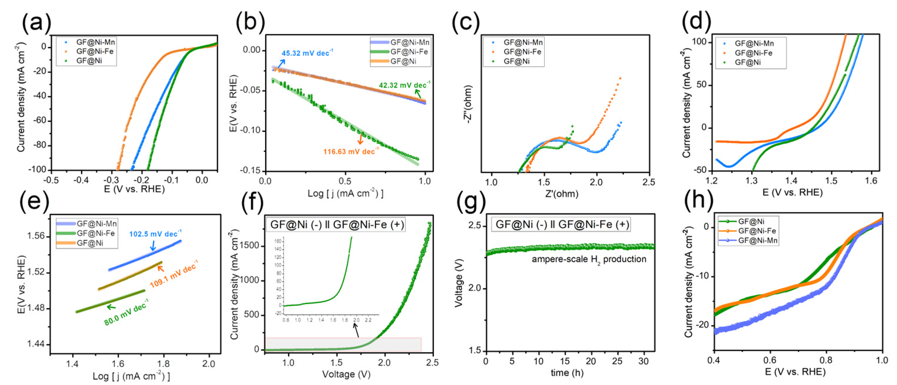
The electrochemical catalytic capabilities of GF-based electrodes were examined using an electrochemical workstation in a 1 M KOH solution, employing a three-electrode configuration with a Hg/HgO reference electrode, a graphite rod as the counter electrode, and the GF-based electrodes as the working electrode. Initially, the HER activity of the samples was assessed through LSV curves, as depicted in Figure 4a. Among the tested samples, GF@Ni exhibited superior HER activity, attributed to the presence of Ni and Ni(OH)2 heterostructures [14,26,27], with the lowest overpotential of only 82 mV required to achieve a current density of 20 mA cm−2, compared to GF@Ni-Mn (92 mV) and GF@Ni-Fe (169 mV). The Tafel plots (Figure 4b) show GF@Ni with the smallest Tafel slope of 42.32 mV dec−1, indicating advantageous HER kinetics. The Nyquist plot (Figure 4c) demonstrates similar high-frequency resistance (RHFR) values for all samples, suggesting comparable electrical conductivity. However, the notably lower charge transfer resistance (Rct) of GF@Ni points to its faster HER kinetics and charge transfer efficiency. For OER activity, reverse-direction LSV scans were performed for the three samples, as shown in Figure 4d, to avoid overestimation of OER activity due to overlapping Ni(FeMn) redox peaks. A significant reduction peak around 1.3–1.4 VRHE in the GF@Ni-Fe sample indicates the formation of NiFe(oxy)hydroxide, known for its superior OER catalytic activity [28,29,30]. As anticipated, GF@Ni-Fe displayed the best OER performance with an overpotential of approximately 239 mV at 20 mA cm−2, lower than GF@Ni (257 mV) and GF@Mn (276 mV). The lowest Tafel slope of GF@Ni-Fe was observed in Figure 4e, indicating its favorable OER kinetics. For the overall water electrolysis system, GF@Ni as the cathode for HER and GF@Ni-Fe as the anode for OER were combined, with the LSV curve of this system shown in Figure 3f. To produce a current density of 20 mA cm−2, an applied voltage of 1.60 V was required, and ampere-scale hydrogen production was achieved at 2.3 V for a current density of 1.0 A cm−2 under ambient conditions. The durability of this overall water-splitting system was tested through chronoamperometric measurement (Figure 4f), maintaining a stable voltage of 2.3 V at 1 A cm−2 current density for over 30 h. Additionally, ORR activity was evaluated in an O2-saturated 1 M KOH electrolyte for the three samples. GF@Ni-Mn demonstrated a rapid current increase at increased overpotentials due to ORR-active manganese oxide. It should be noted that the electrodeposition time for both GF@Ni-Fe and GF@Ni-Mn samples was also evaluated. The findings, as depicted in Figure S9a,b, indicate that an optimal electrodeposition time of 10 min was established for each sample. However, the lower OER activity of GF@Ni-Mn as an air cathode poses a challenge to the rechargeability of ZABs.
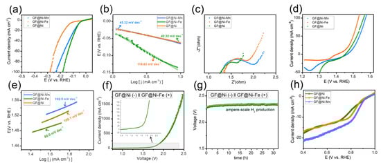
Figure 4.
(a) LSV curves of GF-based electrodes in 1 M KOH electrolyte with a scan rate of 0.5 mV s−1, and (b) the corresponding Tafel plots from panel (a). (c) Nyquist plots toward HER. (d) LSV curves of GF-based electrodes in 1 M KOH electrolyte with a scan rate of 0.5 mV s−1, and (e) the corresponding Tafel plots from panel (d). (f) LSV curves of GF@Ni (−) ║ GF@Ni-Fe(+) alkaline water electrolysis system, and (g) the chronoamperometric measurement at 1.0 A cm−2 of current density. (h) LSV curves of GF-based electrodes in O2-saturated 1 M KOH, demonstrating the ORR activity of the electrodes.
3.3. Sulfurization of GF@Ni-Mn for Application in Rechargeable Solid-State Zinc–Air Batteries
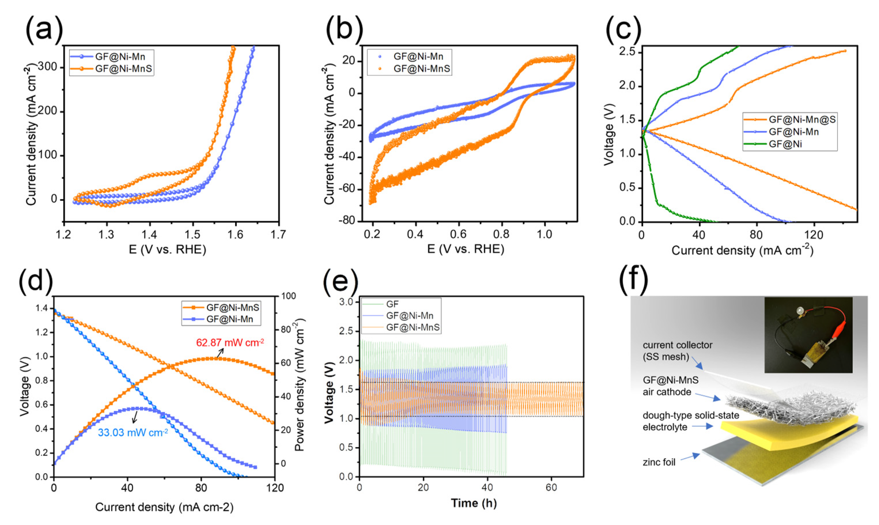
Metal sulfides have been identified as emerging electrocatalysts that significantly enhance the bi-functional activity in zinc–air batteries [31,32,33]. Consequently, GF@Ni-Mn was subjected to thermal sulfurization with sulfur powder, transforming it into GF@Ni-MnS at 450 °C for 2 h under an argon atmosphere. The XRD pattern in Figure 5a shows new peaks corresponding to NiS2 (JCPDS card No. 03-0734) and α-MnS (JCPDS card No. 06-0518) while retaining metallic Ni peaks, indicative of partial sulfurization. XPS survey spectrum (Figure 5b) confirmed the presence of S, C, Ni, and Mn, with fine spectra for C1s (Figure 5c), Ni2p (Figure 5d), and Mn2p (Figure 5e) revealing similar chemical states to those of GF@Ni-Mn. In Figure 5f, the S1s spectrum reveals peaks at 162.0 eV and 163.4 eV, which are indicative of metal–sulfur bonding. Additionally, a peak at approximately 168.7 eV is observed, corresponding to a C-S bond [34]. The overall fibrous structure of the felt was well-preserved post-sulfurization, as seen in Figure 5g,h, and the high-resolution SEM images (Figure S10a,b) confirmed the relatively rough surface of microfibers in GF@Ni-MnS. The cross-sectional fiber image in (Figure S11a) shows the maintenance of core–multiple shell layers comprising carbonaceous core and Ni-(Ni)MnS shells. EDS elemental mapping, presented in Figure S11b, distinctly delineates the carbon core and the Ni-Mn-S shells. Additionally, low-resolution EDS mapping images, depicted in Figure 5i, illustrate the uniform distribution of C, S, Ni, and Mn across the entire fibrous matrix. The bi-functional activity of GF@Ni-MnS for oxygen-related redox reactions was evaluated and compared to GF@Ni-Mn. Cyclic voltammetry (CV) scans at a slow scan rate of 0.5 mV s−1 were conducted to accurately assess OER and ORR activities. Figure 6a shows that GF@Ni-MnS exhibited superior OER activity to GF@Ni-Mn, with an overpotential of approximately 197 mV at a current density of 20 mA cm−2. Furthermore, the ORR activity of GF@Ni-MnS was significantly enhanced, as indicated in Figure 6b, with a higher limiting current density of 60 mA cm−2 at 0.2 VRHE compared to ~26 mA cm−2 for GF@Ni-Mn. The potential at 10 mA cm−2 was 0.883 VRHE for GF@Ni-MnS, which is much higher compared to 0.773 VRHE for GF@Ni-Mn. Encouraged by its improved bi-functional activity, a solid-state ZAB was assembled using a GF-based electrode as the air cathode, zinc foil as the anode, and a viscoelastic sodium alginate–KOH dough-type solid-state electrolyte. The galvanostatic mode charge–discharge polarization curve (Figure 6c) demonstrated a significantly smaller voltage gap for GF@Ni-MnS across all current ranges. The peak power density for ZABs with the GF@Ni-MnS air cathode reached 62.87 mW cm−2, markedly higher than 33.03 mW cm−2 for GF@Ni-Mn (Figure 6d). In the cyclic performance test (Figure 6e), the initial voltage gap between charging and discharging for GF@Ni-MnS was 0.70 V (1.79 V–1.09 V), significantly smaller than for GF@Ni-Mn (0.93 V) or GF@Ni (2.13 V). This cyclic stability persisted over 70 h charging–discharging cycles. These components could be arranged in a sandwich-type battery configuration, as depicted in Figure 6f, with such a configuration capable of powering an LED lamp, as shown in the inset image. After operating ZABs for 70 h, the air cathode was thoroughly rinsed. Subsequent tracking of its chemical state changes through XPS analysis, as illustrated in Figure S12a–c, revealed negligible alterations. This suggests the chemical robustness of the GF@Ni-MnS air cathode.
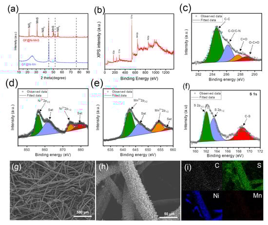
Figure 5.
(a) XRD patterns of GF@Ni-Mn and GF@Ni-MnS. (b) XPS survey spectrum and high-resolution spectra for (c) C 1s, (d) Ni 2p, (e) Mn 2p, and (f) S 1s of GF@Ni-MnS, respectively. (g,h) SEM images of GF@Ni-MnS and (i) EDX elemental mapping images showing the distribution of elements for C, S, Ni, and Mn.
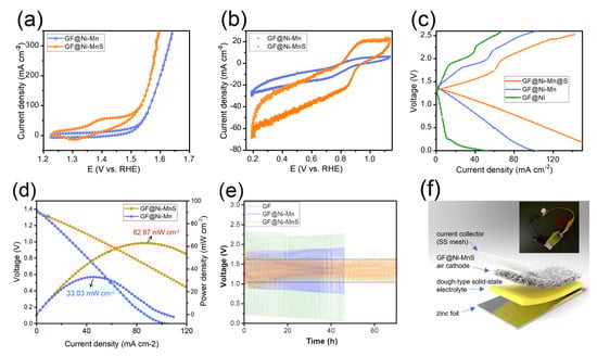
Figure 6.
(a) LSV curves of GF@Ni-Mn and GF@Mn-MnS in 1 M KOH for OER. (b) CV curves in O2-saturated 1 M KOH for ORR. (c) Galvanostatic charge–discharge polarization curves; (d) discharge polarization and corresponding power density curves of ZABs with GF@Ni-Mn and GF@Ni-MnS air cathodes. (e) Cyclic performance of solid-state ZABs with GF-based air cathodes. (f) Schematic of a solid-state ZAB with GF@Ni-MnS air cathode and an inset photo of the battery powering an LED lamp.
4. Discussion
In this study, we explored the use of graphite felt (GF) as a versatile, economically viable electrode in energy storage and conversion systems, addressing the challenges often associated with conductive substrates. Our approach involved enhancing the traditionally low conductivity of GF through interfacial chemical tuning and the electrodeposition of a nickel layer, thereby allowing the integration of various transition metal-based active sites. This modification was key in improving catalytic activity for specific electrochemical reactions. A significant outcome of our research was the development of a nickel-rich cathode and an iron-rich anode, which demonstrated optimized performance in alkaline water electrolysis for hydrogen production at the ampere scale. This finding aligns with the broader objective of enhancing electrocatalytic efficiency in energy systems. Further, the addition of sulfur to these electrodes led to notable improvements in bi-functional oxygen-related redox reactions, making them particularly suitable for air cathodes in solid-state zinc–air batteries (ZABs). The sulfurized GF@Ni-Mn electrodes exhibited remarkable performance in solid-state ZABs, highlighted by a peak power density of 62.9 mW cm−2, minimal voltage gap in discharge–charge polarization, and a lifecycle exceeding 70 h. These improvements in electrochemical activities, especially in oxygen-related redox reactions, underline the superiority of multi-component electrocatalysts over single or binary systems.
This study not only introduces GF-based electrodes as a promising material for efficient and sustainable energy storage and conversion but also demonstrates their exceptional catalytic activities, characterized by low overpotential values and superior performance in overall water-splitting and zinc–air battery applications. These results align well with the leading performances reported in recent literature in this field [35,36,37,38,39,40]. Future research should focus on exploring the effects of sulfurization across various metal combinations and conditions, conducting long-term stability tests under practical operating scenarios, and evaluating scalability and environmental impacts for commercialization. This research not only advances our understanding of electrode materials but also paves the way for future interdisciplinary efforts to tackle global energy challenges, integrating comprehensive insights from the entire scope of this study.
Supplementary Materials
The following supporting information can be downloaded at https://www.mdpi.com/article/10.3390/batteries10020049/s1, Figure S1: (a) Photograph images of untreated graphite felt floating on the surface of distilled water in a water bath, and (b) COOH-functionalized graphite felt fully immersed in water; Figure S2: SEM images of nickel electroplated graphite felt samples at 4.0 V under various conditions: (a,b) on untreated GF for 10 minutes, on AA-GF with nickel (GF@Ni) (c,d) for 10 minutes, and (e,f) for 20 minutes, respectively; Figure S3: LSV curves of nickel electroplated graphite felt samples at 4.0 V under various conditions, tested in a 1.0 M KOH electrolyte for HER; Figure S4: SEM images of (a) GF@Ni-Mn and (b) GF@Ni-Fe. Figure S5. SEM images of cross-section of GF@Ni-Mn. Figure S6. XPS survey spectrum of fine O1s spectrum of GF@Ni; Figure S7: XPS fine (a) C1s and (b) Ni2p spectrum of GF@Ni-Mn; Figure S8: XPS fine (a) C1s and (b) Ni2p spectrum of GF@Ni-Fe; Figure S9: (a) LSV curves of GF@Ni-Fe electrodes subjected to varying electrodeposition times of 2, 5, 10, and 20 minutes in 1 M KOH electrolyte, aimed at evaluating the OER activity of these electrodes. (b) LSV curves of GF@Ni-Mn and GF@Ni-Fe electrodes, each with electrodeposition times of 2, 5, 10, and 20 minutes, conducted in O2-saturated 1 M KOH to assess the ORR activity of these electrodes; Figure S10: (a‒c) SEM images of GF@Ni-MnS; Figure S11: (a,b) EDX elemental mapping images showing the distribution of elements for C, S, Ni, and Mn; Figure S12: XPS fine (a) S1s, (b) Ni2p, (c) Mn2p spectrums of GF@Ni-MnS after cyclic test of ZABs.
Author Contributions
Y.L.: methodology, data curation, investigation, and writing—original draft preparation. S.-h.P.: data curation and investigation. S.H.A.: conceptualization, methodology, writing—review and editing, supervision, project administration, and funding acquisition. All authors have read and agreed to the published version of the manuscript.
Funding
This research was supported by the “Regional Innovation Strategy (RIS)” through the National Research Foundation of Korea (NRF), funded by the Ministry of Education (MOE) (2021RIS-002). This work was also supported by NRF grants funded by the Ministry of Science, ICT and Future Planning (Nos. NRF-2018R1C1B6005009, NRF-2021R1C1C1012676, and 2009-0082580).
Data Availability Statement
The data presented in this study are available on request from the corresponding author. They are not publicly available due to their ongoing use in related, unpublished research.
Conflicts of Interest
The authors declare no conflicts of interest.
References
- Tang, J.; Xu, X.; Tang, T.; Zhong, Y.; Shao, Z. Perovskite-Based Electrocatalysts for Cost-Effective Ultrahigh-Current-Density Water Splitting in Anion Exchange Membrane Electrolyzer Cell. Small Methods 2022, 6, 2201099. [Google Scholar] [CrossRef]
- Milikić, J.; Nastasić, A.; Martins, M.; Sequeira, C.A.C.; Šljukić, B. Air Cathodes and Bifunctional Oxygen Electrocatalysts for Aqueous Metal–Air Batteries. Batteries 2023, 9, 394. [Google Scholar] [CrossRef]
- Sun, H.; Xu, X.; Kim, H.; Shao, Z.; Jung, W. Advanced electrocatalysts with unusual active sites for electrochemical water splitting. InfoMat 2023, 6, e12494. [Google Scholar] [CrossRef]
- Spöri, C.; Kwan, J.T.H.; Bonakdarpour, A.; Wilkinson, D.P.; Strasser, P. The Stability Challenges of Oxygen Evolving Catalysts: Towards a Common Fundamental Understanding and Mitigation of Catalyst Degradation. Angew. Chem. Int. Ed. 2017, 56, 5994–6021. [Google Scholar] [CrossRef]
- Castañeda, L.F.; Walsh, F.C.; Nava, J.L.; de León, C.P. Graphite felt as a versatile electrode material: Properties, reaction environment, performance and applications. Electrochim. Acta 2017, 258, 1115–1139. [Google Scholar] [CrossRef]
- Jialin, Z.; Yiyang, L.; Shanfu, L.; Yan, X. Nitrogen, Phosphorus Co-Doped Graphite Felt as Highly Efficient Electrode for VO2+/VO2+ Reaction. Batteries 2023, 9, 40. [Google Scholar] [CrossRef]
- Lei, L.; Yin, Z.; Huang, D.L.; Chen, Y.S.; Chen, S.; Cheng, M.; Du, L.; Liang, Q.H. Metallic Co and crystalline Co-Mo oxides supported on graphite felt for bifunctional electrocatalytic hydrogen evolution and urea oxidation. J. Colloid Interface Sci. 2022, 612, 413–423. [Google Scholar] [CrossRef]
- Deng, B.; Liang, J.; Yue, L.C.; Li, T.S.; Liu, Q.; Liu, Y.; Gao, S.Y.; Alshehri, A.A.; Alzahrani, K.A.; Luo, Y.L.; et al. CoFe-LDH nanowire arrays on graphite felt: A high-performance oxygen evolution electrocatalyst in alkaline media. Chin. Chem. Lett. 2022, 33, 890–892. [Google Scholar] [CrossRef]
- Tong, X.; Pang, N.; Qu, Y.; Yan, C.; Xiong, D.; Xu, S.; Wang, L.; Chu, P.K. 3D urchin-like NiCo2O4 coated with carbon nanospheres prepared on flexible graphite felt for efficient bifunctional electrocatalytic water splitting. J. Mater. Sci. 2021, 56, 9961–9973. [Google Scholar] [CrossRef]
- Shi, H.Y.; Zhang, Y.Y.; Pang, N.; Wu, D.J.; Yang, Z.Z.; Xu, S.H.; Xiong, D.Y.; Wang, L.W.; Yang, P.X.; Chu, P.K. Surface modulation of transition-metal-doped MoS2@graphite felt for bifunctional catalysis in Zn-air batteries. Electrochim. Acta 2024, 475, 143670. [Google Scholar] [CrossRef]
- Lee, H.U.; Yang, I.; Chung, B.G.; Jin, J.H. Pen-drawn air cathode featuring graphite felt substrate modified with MnO2-decorated graphene flakes and PEDOT network for rechargeable zinc-air battery. J. Ind. Eng. Chem. 2022, 108, 411–417. [Google Scholar] [CrossRef]
- Yang, H.; Wan, Y.; Sun, K.; Zhang, M.; Wang, C.; He, Z.; Li, Q.; Wang, N.; Zhang, Y.; Hu, H.; et al. Reconciling Mass Loading and Gravimetric Performance of MnO2 Cathodes by 3D-Printed Carbon Structures for Zinc-Ion Batteries. Adv. Funct. Mater. 2023, 33, 2215076. [Google Scholar] [CrossRef]
- Wang, J.; Guo, W.; Liu, Z.; Zhang, Q. Engineering of Self-Aggregation-Resistant MnO2 Heterostructure with A Built-in Field for Enhanced High-Mass-Loading Energy Storage. Adv. Energy Mater. 2023, 13, 2300224. [Google Scholar] [CrossRef]
- Mo, J.; Ko, Y.; Yun, Y.S.; Huh, J.; Cho, J. A carbonization/interfacial assembly-driven electroplating approach for water-splitting textile electrodes with remarkably low overpotentials and high operational stability. Energy Environ. Sci. 2022, 15, 3815–3829. [Google Scholar] [CrossRef]
- Kawashima, K.; Márquez, R.A.; Son, Y.J.; Guo, C.; Vaidyula, R.R.; Smith, L.A.; Chukwuneke, C.E.; Mullins, C.B. Accurate Potentials of Hg/HgO Electrodes: Practical Parameters for Reporting Alkaline Water Electrolysis Overpotentials. ACS Catal. 2023, 13, 1893–1898. [Google Scholar] [CrossRef]
- Jeon, O.S.; Ko, E.S.; Park, Y.Y.; Hong, D.; Lee, S.H.; Jeon, Y.P.; La, Y.; Kim, S.; Lee, I.-S.; Park, G.-S.; et al. Hygroscopic and Malleable Dough-Type Zn–Air Battery in a Dry Condition Utilizing Deliquescence. Adv. Energy Mater. 2023, 13, 2300285. [Google Scholar] [CrossRef]
- Wang, P.; Lin, Y.; Wan, L.; Wang, B. Construction of a Janus MnO2-NiFe Electrode via Selective Electrodeposition Strategy as a High-Performance Bifunctional Electrocatalyst for Rechargeable Zinc–Air Batteries. ACS Appl. Mater. Interfaces 2019, 11, 37701–37707. [Google Scholar] [CrossRef]
- Zou, X.; Sun, Q.; Zhang, Y.; Li, G.-D.; Liu, Y.; Wu, Y.; Yang, L.; Zou, X. Ultrafast surface modification of Ni3S2 nanosheet arrays with Ni-Mn bimetallic hydroxides for high-performance supercapacitors. Sci. Rep. 2018, 8, 4478. [Google Scholar] [CrossRef]
- Huang, C.; Zhang, Y.; Li, X.; Cao, H.; Guo, Y.; Zhang, C. Mn-incorporated Co3O4 bifunctional electrocatalysts for zinc-air battery application: An experimental and DFT study. Appl. Catal. B Environ. 2022, 319, 121909. [Google Scholar] [CrossRef]
- Pei, Y.R.; Zhao, M.; Zhu, Y.P.; Yang, C.C.; Jiang, Q. VN nanoparticle-assembled hollow microspheres/N-doped carbon nanofibers: An anode material for superior potassium storage. Nano Mater. Sci. 2022, 4, 104–112. [Google Scholar] [CrossRef]
- Chen, B.; Miao, H.; Yin, M.; Hu, R.; Xia, L.; Zhang, C.; Yuan, J. Mn-based spinels evolved from layered manganese dioxides at mild temperature for the robust flexible quasi-solid-state zinc-air batteries. Chem. Eng. J. 2021, 417, 129179. [Google Scholar] [CrossRef]
- Ilton, E.S.; Post, J.E.; Heaney, P.J.; Ling, F.T.; Kerisit, S.N. XPS determination of Mn oxidation states in Mn (hydr)oxides. Appl. Surf. Sci. 2016, 366, 475–485. [Google Scholar] [CrossRef]
- Harish, K.; Balamurugan, J.; Nguyen, T.T.; Kim, N.H.; Lee, J.H. Advanced interfacial engineering of oxygen-enriched FexSn1−xOSe nanostructures for efficient overall water splitting and flexible zinc-air batteries. Appl. Catal. B Environ. 2022, 305, 120924. [Google Scholar] [CrossRef]
- Fu, R.; Feng, C.; Jiao, Q.; Ma, K.; Ge, S.; Zhao, Y. Molybdate intercalated nickel–iron-layered double hydroxide derived Mo-doped nickel–iron phosphide nanoflowers for efficient oxygen evolution reaction. Energy Mater. Devices 2023, 1, 9370002. [Google Scholar] [CrossRef]
- Liang, C.W.; Zou, P.C.; Nairan, A.; Zhang, Y.Q.; Liu, J.X.; Liu, K.W.; Hu, S.Y.; Kang, F.Y.; Fan, H.J.; Yang, C. Exceptional performance of hierarchical Ni-Fe oxyhydroxide@NiFe alloy nanowire array electrocatalysts for large current density water splitting. Energy Environ. Sci. 2020, 13, 86–95. [Google Scholar] [CrossRef]
- Zhong, W.; Li, W.; Yang, C.; Wu, J.; Zhao, R.; Idrees, M.; Xiang, H.; Zhang, Q.; Li, X. Interfacial electron rearrangement: Ni activated Ni(OH)2 for efficient hydrogen evolution. J. Energy Chem. 2021, 61, 236–242. [Google Scholar] [CrossRef]
- Lai, W.; Ge, L.; Li, H.; Deng, Y.; Xu, B.; Ouyang, B.; Kan, E. In Situ Raman spectroscopic study towards the growth and excellent HER catalysis of Ni/Ni(OH)2 heterostructure. Int. J. Hydrogen Energy 2021, 46, 26861–26872. [Google Scholar] [CrossRef]
- Zhao, W.; Xu, H.; Luan, H.; Chen, N.; Gong, P.; Yao, K.; Shen, Y.; Shao, Y. NiFe Layered Double Hydroxides Grown on a Corrosion-Cell Cathode for Oxygen Evolution Electrocatalysis. Adv. Energy Mater. 2022, 12, 2102372. [Google Scholar] [CrossRef]
- Lei, H.; Ma, L.; Wan, Q.; Tan, S.; Yang, B.; Wang, Z.; Mai, W.; Fan, H.J. Promoting Surface Reconstruction of NiFe Layered Double Hydroxide for Enhanced Oxygen Evolution. Adv. Energy Mater. 2022, 12, 2202522. [Google Scholar] [CrossRef]
- Zhong, D.Z.; Zhang, L.; Li, C.C.; Li, D.D.; Wei, C.C.; Zhao, Q.; Li, J.P.; Gong, J.L. Nanostructured NiFe (oxy)hydroxide with easily oxidized Ni towards efficient oxygen evolution reactions. J. Mater. Chem. A 2018, 6, 16810–16817. [Google Scholar] [CrossRef]
- Wu, H.; Li, Z.; Wang, Z.; Ma, Y.; Huang, S.; Ding, F.; Li, F.; Zhai, Q.; Ren, Y.; Zheng, X.; et al. Regulation of electronic structure in medium-entropy metal sulfides nanoparticles as highly efficient bifunctional electrocatalysts for zinc-air battery. Appl. Catal. B Environ. 2023, 325, 122356. [Google Scholar] [CrossRef]
- Dang, J.; Yin, M.; Pan, D.; Tian, Z.; Chen, G.; Zou, J.; Miao, H.; Wang, Q.; Yuan, J. Four-functional iron/copper sulfide heterostructure for alkaline hybrid zinc batteries and water splitting. Chem. Eng. J. 2023, 457, 141357. [Google Scholar] [CrossRef]
- Wang, A.; Zhang, X.; Gao, S.; Zhao, C.; Kuang, S.; Lu, S.; Niu, J.; Wang, G.; Li, W.; Chen, D.; et al. Fast-Charging Zn–Air Batteries with Long Lifetime Enabled by Reconstructed Amorphous Multi-Metallic Sulfide. Adv. Mater. 2022, 34, 2204247. [Google Scholar] [CrossRef]
- Wu, D.; Xie, X.B.; Zhang, J.J.; Ma, Y.P.; Hou, C.X.; Sun, X.Q.; Yang, X.Y.; Zhang, Y.P.; Kimura, H.; Du, W. Embedding NiS nanoflakes in electrospun carbon fibers containing NiS nanoparticles for hybrid supercapacitors. Chem. Eng. J. 2022, 446, 137262. [Google Scholar] [CrossRef]
- Li, J.; Sun, J.P.; Li, Z.Z.; Meng, X.C. Recent advances in electrocatalysts for seawater splitting in hydrogen evolution reaction. Int. J. Hydrogen Energy 2022, 47, 29685–29697. [Google Scholar] [CrossRef]
- Pang, Y.; Zhu, S.L.; Cui, Z.D.; Liang, Y.Q.; Li, Z.Y.; Wu, S.L. Self-supported amorphous nanoporous nickel-cobalt phosphide catalyst for hydrogen evolution reaction. Prog. Nat. Sci.-Mater. Int. 2021, 31, 201–206. [Google Scholar] [CrossRef]
- Li, Y.; Ma, D.W.; Wang, Y.T.; Yang, H.B.; Lou, Z.R.; Qin, R.Z.; Zhao, Q.H.; Pan, F.; Liu, H.K. A novel bimetallic RuFe nanocluster to enable highly efficient oxygen reduction in zinc-air batteries. Prog. Nat. Sci.-Mater. Int. 2022, 32, 769–775. [Google Scholar] [CrossRef]
- Lee, S.; Choi, J.; Kim, M.; Park, J.; Park, M.; Cho, J. Material design and surface chemistry for advanced rechargeable zinc-air batteries. Chem. Sci. 2022, 13, 6159–6180. [Google Scholar] [CrossRef]
- Chatenet, M.; Pollet, B.G.; Dekel, D.R.; Dionigi, F.; Deseure, J.; Millet, P.; Braatz, R.D.; Bazant, M.Z.; Eikerling, M.; Staffell, I.; et al. Water electrolysis: From textbook knowledge to the latest scientific strategies and industrial developments. Chem. Soc. Rev. 2022, 51, 4583–4762. [Google Scholar] [CrossRef]
- Long, X.Y.; Meng, J.Z.; Gu, J.B.; Ling, L.Q.; Li, Q.W.; Liu, N.; Wang, K.W.; Li, Z.Q. Interfacial Engineering of NiFeP/NiFe-LDH Heterojunction for Efficient Overall Water Splitting. Chin. J. Struct. Chem. 2022, 41, 2204046–2204053. [Google Scholar]


Disclaimer/Publisher’s Note: The statements, opinions and data contained in all publications are solely those of the individual author(s) and contributor(s) and not of MDPI and/or the editor(s). MDPI and/or the editor(s) disclaim responsibility for any injury to people or property resulting from any ideas, methods, instructions or products referred to in the content. |
© 2024 by the authors. Licensee MDPI, Basel, Switzerland. This article is an open access article distributed under the terms and conditions of the Creative Commons Attribution (CC BY) license (https://creativecommons.org/licenses/by/4.0/).