Abstract
The extensive utilization of lithium-ion (Li-ion) batteries within the automotive industry necessitates rigorous measures to ensure their mechanical robustness, crucial for averting thermal runaway incidents and ensuring vehicle safety. This paper introduces an innovative methodology aimed at homogenizing the mechanical response of Li-ion batteries under compression load, using Finite Element Method (FEM) techniques to improve computational efficiency. A novel approach is proposed, involving the selective application of compression loads solely to the Jelly Roll and its casing, achieved by cutting the battery heads. Through this method, distinct mechanical behaviors are identified within the battery force displacement curve: an elastic region, a zone characterized by plastic deformation, and a segment exhibiting densification. By delineating these regions, our study facilitates a comprehensive understanding of the battery’s mechanical response under compression. Two battery models were employed in this study: one representing the battery as a solid volume, and another featuring the jelly roll as a solid volume enclosed by a shell representing the casing. The material utilized was LS Dyna MAT24, chosen for its piecewise characteristics’ definition, and its validation was primarily conducted through the curve fitting method applied to the force–displacement curve, taking in account the three regions of the compression force behavior. This approach not only optimizes computational resources but also offers insights crucial for enhancing the mechanical stability of Li-ion batteries in automotive applications.
1. Introduction
Li-ion batteries are used in many consumer electronic devices, such as laptops and smartphones, as well as in electric vehicles (EVs) and other applications where their high energy density, low self-discharge, and relatively low maintenance make them a suitable choice. However, like any type of battery, Li-ion batteries have the potential to fail, which can lead to hazards, such as thermal runaway, fire and explosion, well documented in [1,2]. One important aspect of Li-ion battery design is crashworthiness, or the ability of the battery to withstand impact, vibration, and other mechanical stresses. This is especially important in EVs, where the battery is a critical component of the vehicle and must be able to withstand the rigors of the road. Crashworthiness is also important in consumer electronics, where drops and other accidental impacts are common.
In the pursuit of enhancing the crashworthiness and safety of Li-ion batteries, a range of mechanical loading scenarios are investigated to evaluate their structural response and potential risks in various conditions. One crucial aspect is the investigation of nail penetration tests, where external objects puncture the battery casing, simulating potential scenarios, such as mishandling or manufacturing defects. A safe, time-efficient, and cost-effective method for studying the nail penetration problem is proposed in [3,4]. Additionally, dropping tests are conducted to simulate accidental falls or impacts during transportation and handling [5]. In the context of automotive safety, Li-ion batteries are subjected to compression loads that replicate the forces experienced during car crashes; the applied crush force emulates a vehicle accident, or any external load force that may damage the battery enclosure and cause its deformation. This subject is discussed extensively in the safety and regulation review papers of [6,7]. The comprehensive investigations found in the literature aid in understanding the battery’s behavior under different mechanical loads, identifying potential failure modes, and designing safety measures to mitigate risks associated with thermal runaway, short circuits, and containment breaches [8,9,10,11,12,13,14,15]. In [13], short-circuit criteria are investigated and compared, based on stress, strain, and geometry in simulations with FEM, demonstrating that a combination of radial and axial geometric criteria is optimal; furthermore, these criteria are implemented into a post-processing tool for efficient short-circuit analysis across various loadings and potential mechanical integration in vehicle crash safety.
A Li-ion battery is composed of several essential structural components that collectively enable its energy storage function. The anode and cathode, or the current collectors, are fundamental electrodes that store and release lithium ions during charging and discharging cycles. They are typically made of copper or aluminum and exhibit mechanical properties such as anisotropy, strain hardening, ductile fracture, and rate-dependence. The separator layer, situated between the anode and cathode, serves as an insulating barrier to prevent direct contact between the electrodes. This separator often consists of polymer with orthotropy and elasto-viscoplasticity as mechanical properties. The case shell is made from steel or aluminum sheet, with such mechanical attributes as anisotropy, strain hardening, and ductile fracture, and plays an important part in the structural integrity of the battery [16].
The interaction between these layers can affect the battery’s response to mechanical loading, influencing factors such as deformation, stress distribution, and failure modes. Simulating the mechanical properties of these components consumes a great deal of the computing resources in large-scale and complex FEM models. In a detailed model of the battery, there are more than 100,000 elements [16] and a Tesla Model S, for example, has about 7000 cells [17] of type 18650, that will count 700 million elements. In [17], the optimization of the FEM model is investigated by dividing it into beam elements representing different components with separate mechanical properties and reducing the computation time by 90%. This paper proposes a further step, with homogenization of the battery in a simple representative volume for simulations and analyses of the battery’s behavior under compression loads, and can be used in larger scale vehicle model safety simulations.
In recent years, computational methods have played an increasingly vital role in investigating the mechanical properties of complex structures, including Li-ion batteries [18]. Finite Element Analysis (FEA) is a powerful numerical technique that can simulate the behavior of materials and structures under various loading conditions. LS Dyna version R11, a commercial software package, is widely employed for such simulations due to its versatility and accuracy in capturing complex material responses [19]. The focus of this study is the mechanical homogenization of a Li-ion cylindrical battery under compression load using LS Dyna Finite Element Analysis [8,20], specifically employing a plastic material model within the software. Plastic material models are commonly used to represent the behavior of materials that undergo large deformation and energy absorption under compression. Efficient computational methods are paramount in large-scale simulations, such as Li-ion battery analysis. The homogenization approach adopted in this study offers a unique advantage by reducing the complexity of the modeling of individual battery components, resulting in significant computational savings. This reduction in computational burden allows for quicker simulations, enabling researchers and engineers to explore a wider range of scenarios and design options. Although the advantages of the homogenized model are evident in terms of computational efficiency, there is a limitation, particularly in accurately predicting jelly roll layer failure. Homogenized models, by simplifying the battery’s multi-layered structure, lose some of the granularity required to capture intricate failure mechanisms such as internal short circuits or localized deformation of layers under extreme loading. This limitation is mitigated by supplementing the homogenized models with insights from detailed models or experimental data. In these studies, parameters such as deformation limits and failure thresholds are derived from high-fidelity models or direct testing [20]. These values are then applied to set safety margins in the larger computational models, ensuring that the simulations remain both computationally efficient and reflective of critical safety conditions. This hybrid approach enables researchers to use homogenized models for large-scale safety analysis while still addressing the detailed failure modes that could compromise the integrity of the battery pack under crash conditions.
The specific focus on the mechanical behavior of the homogenization of cylindrical Li-ion batteries using a plastic material model and its computational benefits remains a gap in the current literature. The objective of this paper is to address this gap by systematically studying the mechanical behavior of a Li-ion cylindrical battery under compression load, using a homogenization approach with a plastic material model in LS Dyna. Through a comprehensive simulation study, we aim to provide insights into the macroscopic mechanical properties of the battery, enhance our understanding of its behavior under compression and improve computational efficiency through the homogenization technique, contributing to the broader knowledge of Li-ion battery mechanics.
2. Physical Experiment Description
2.1. Test Description
In the physical test, 18650 Li-ion batteries sourced from Tesla Model S vehicles were subjected to compression testing to ascertain their material properties, followed by validation using Finite Element Method (FEM) modeling. Compression testing offers insights into the batteries’ response to external forces, generating a force–deformation curve that unveils pivotal mechanical characteristics. By subjecting the batteries to controlled compression, the material model can be validated against real-world behavior, facilitating accurate simulations for compression scenarios. The validation of material models for Finite Element simulation is very important in ensuring accurate prediction of mechanical behaviors. In this context, the validation of a very simplified model is achieved through a twofold approach, with the emphasis on analyzing the force–deformation curve and comparing the overall deformation patterns. The force–deformation curve, obtained from compression testing, serves as a fundamental benchmark. By comparing the simulation results with the experimental force–deformation data, the simplified FEM model’s accuracy in capturing the battery’s response to external loading is assessed. The combined validation of force–deformation responses and deformation patterns establishes a robust framework for utilizing simplified FEM simulations as predictive tools for optimizing the design, safety, and performance of 18650 Li-ion batteries in more complex, pack or full vehicle safety simulation.
For the 18650 battery the external dimensions are 18 mm radius and 65 mm length. The main relevant structural composition is the shell case, and in the case of Tesla batteries two case shells; a robust enclosure enveloping the battery’s core components acts as the initial line of defense against external impacts, fortifying the battery’s inner workings. Inside the case shell, there is a jelly roll of the current collectors, anode, and cathode materials, each performing a distinct yet synergistic role. The current collectors are rolled more than 20 times with a cylindrical gap in the middle. Nestled between these electrodes lies the separator, which is rolled together with the current collector (Figure 1a). The battery’s mechanically relevant components and their thickness are presented in Table 1.
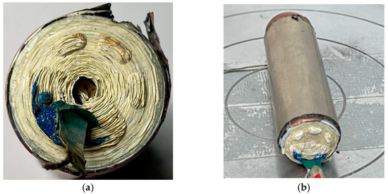
Figure 1.
The 18650-type battery: (a) top view inside the battery, (b) battery without the top and bottom cap.

Table 1.
Mechanically relevant battery components.
In the pursuit of a more refined understanding of the mechanical behavior of the 18650 Li-ion battery under compression, a deliberate and strategic modification was undertaken. Specifically, the upper and lower caps of the battery were cut precisely with the lathe to help ensure precision and a clean cut. The cuts were taken 5 mm from the top, where the shoulder is, and 2 mm from the bottom, and precision was paramount as mm in case length could influence the load results. The battery was discharged for the cutting, but some residual exothermal reaction took place without influencing the main structural components. This surgical alteration was motivated by the recognition that the composition of these caps with steel components could significantly skew the resultant compression forces exerted upon the battery during testing. By adeptly removing this external influence, the focus of investigation was meticulously narrowed to the intrinsic interaction between the battery’s jelly roll—housing the anode, cathode, and separator materials—and the robust outer casing. This strategic excision, while seemingly reductive, was extremely purposeful, serving to isolate and elucidate the core mechanical response of the battery’s internal components and casing when subjected to compression. The resulting insights, untainted by external cap interactions (Figure 1b), foster a more nuanced comprehension of the interplay between structural elements, furthering the discourse on the battery’s mechanical dynamics within the ambit of enhanced safety and operational performance.
The uniaxial compression testing campaign was executed on three samples using an Instron 3366 (10 kN) machine. The compression was executed until a discernible point of densification was achieved, substantiated by the abrupt and pronounced escalation in the force profile. Throughout the entirety of the compression process, a vigilant monitoring of the battery’s voltage was meticulously maintained, as a noticeable drop in the value could predict a short-circuit, in order to prevent a hazardous situation, but also to make sure that a short circuit was not taking place before the densification (Figure 2).

Figure 2.
Battery uniaxial compression test performed on universal testing machine.
The uniaxial compression test conducted on the 18650 Li-ion battery resulted in a non-linear load–displacement curve of important significance, offering valuable insights into the battery’s mechanical behavior under external pressure. This curve can be distinctively categorized into three pivotal zones, each revealing distinct mechanical phenomena, shown in Figure 3. The initial section of the curve, up to an applied load of approximately 2 kN, shows the curve’s elastic domain. Here, the response of the battery is characterized by linear elasticity. As force is applied, the battery’s deformation remains reversible upon unloading, showcasing its ability to withstand external stress while readily returning to its original shape. This zone illustrates the structural resilience of the battery, encapsulating its capacity to temporarily store mechanical energy before yielding to plastic deformation. The deformation in this zone is the smallest, with displacements typically of around 0.5 mm. The elastic module measured is 565, 431 and 551 MPa, respectively, for the three samples with an average of 515 MPa. As an observation, the knee around 0.2 mm could be the yield factor in the plastic deformation of the case, the jelly roll remaining in the elastic domain. Beyond the elastic limit, Zone 2 commences and extends to the onset of the plateau, signifying a critical juncture in the battery’s response. Here, the applied load surpasses the battery’s elastic limit, leading to plastic deformation of the structural components. This plastic deformation is notable, as it occurs without a significant increase in the load, resulting in a discernible load plateau. This phase suggests that the battery’s core structure undergoes irreversible changes while the load remains relatively constant. It is in this zone that the battery’s mechanical integrity begins to be compromised, and deformations are the most significant, reaching values of around 2.5 mm. Zone 3 represents the culmination of the load–displacement curve as the battery undergoes a pronounced densification process. Here, the load increases substantially, reflecting the compression-induced compaction of the battery layers. The battery’s internal components experience significant rearrangement and compaction, resulting in a steep rise in the applied load. This phase signifies a critical point in the test, as it indicates the threshold beyond which the battery’s structural components reach maximum density. This densification zone unveils the limits of the battery’s mechanical tolerance, offering insights into its structural behavior under extreme compression conditions. The test in this zone was stopped at around 7 kN, because densification at that point became a certainty. In summary, the load–displacement curve derived from the uniaxial compression test on the 18650 Li-ion battery illuminates the battery’s complex mechanical response. The distinct zones delineate the battery’s elasticity, plastic deformation, and ultimate densification, all of which contribute to a comprehensive understanding of its mechanical characteristics and inform crucial aspects of design, safety, and performance optimization in various applications.
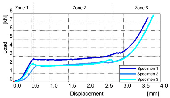
Figure 3.
Uniaxial compression of the battery Load vs. Displacement curve.
In the same manner the Jelly Roll of the battery was tested (Figure 4), with similar results as seen in Figure 5. The elastic module measured is 308 and 176 MPa, respectively, for the two samples, with an average of 242 MPa.
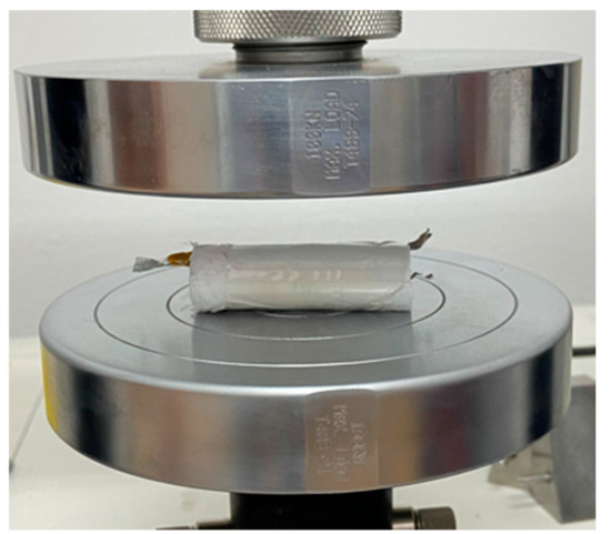
Figure 4.
18640 Battery Jelly Roll uniaxial compression test.
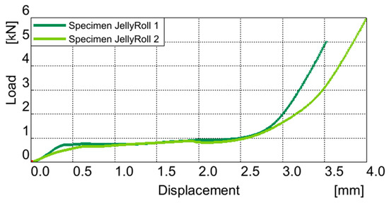
Figure 5.
Uniaxial compression of the jelly roll Load vs. Displacement curve.
2.2. Densification and Failure
The process of densification observed during the uniaxial compression test on the 18650 Li-ion battery layers is a phenomenon documented in the existing literature, as corroborated by similar studies [8,20]. This pivotal stage, marked by a pronounced increase in load, serves as a pivotal juncture where the structural elements within the battery experience a remarkable transformation. To delve deeper into this phenomenon, high-resolution light microscopy was employed, capturing detailed images that elucidate the dynamic interplay between the battery’s internal layers, while also affirming the presence of densification (Figure 6).
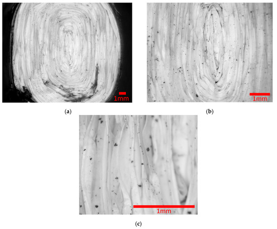
Figure 6.
Microscopic pictures of the battery densification: (a) overall section; (b) middle of the battery section; (c) layers up close.
A visual journey into the densification process of the 18650 Li-ion battery layers was facilitated through light microscopy after unloading, capturing three key snapshots (a, b, c), from Figure 6. In picture (a), we gain an overarching perspective, providing an overall view of the battery section. Transitioning to picture (b), we venture further into the core of the battery, a region subjected to relentless compression forces. Notably, the middle hole is conspicuously absent, underscoring the compaction and deformation incurred during the test. Finally, picture (c) takes us to the heart of the matter—a close-up view that offers a high-resolution look at the battery’s internal layers. What is particularly interesting in this image is the absence of visible space between these layers. This tangible evidence poignantly captures the culmination of the densification process, as the once-distinct layers now tightly interlock, illuminating the profound structural changes unfolding within the battery during compression. These micrographic snapshots, when examined collectively, serve as an invaluable visual record, unraveling the intricate metamorphosis of the battery’s layers and underlining the significance of the densification phenomenon in the realm of Li-ion battery mechanics.
In this stage of densification, failures within the battery jelly roll layers were also observed. These failures (Figure 7) shed light on the critical points of mechanical vulnerability, which, in turn, are intrinsic to understanding the battery’s structural limitations.
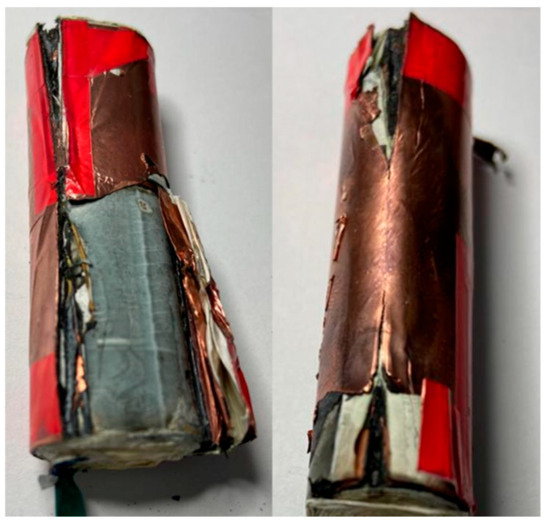
Figure 7.
Failure in the Jelly Roll layers.
3. Model and Material Definition
In this simulation conducted with the LS-DYNA solver, the focus was on a volume representation of an 18650 battery, a widely used cylindrical lithium-ion battery cell, which was then employed to simulate the behavior of the battery under compression mechanical loading. This comprehensive simulation aimed to provide a comparable finite element model with the component test, contributing valuable data for further computing optimization and research into a new method of defining an 18650 battery for large-scale and resource-consuming simulation.
3.1. Model Definition
The computational model intricately replicates the experimental test scenario, featuring a rigid component exerting pressure on the battery, with a rigid wall serving as fixed boundary to emulate the lower support plate of the press. The battery geometry is represented using solid elements within a singular part, characterized by material properties derived from empirical data obtained during the experimental phase. This singular part design aims to encapsulate the nuanced and intricate behavior of the battery in a manner that is both straightforward and comparable. Notably, key parameters, such as the stress–strain curve and compressive force were crucial for accurately capturing the dynamic response of the battery. Given the inherent complexity of the actual system, parameters including density and Young’s modulus underwent optimization through the simulation process to align the model with the intricate characteristics observed in the real-world scenario.
The simulation model comprises a rigid barrier, defined as a shell part consisting of eight quadrilateral elements, each assigned an LS Dyna rigid material property. This rigid barrier is in contact with a battery, which is situated on an LS Dyna rigid wall surface specifically defined as a flat infinite plane (Figure 8a).

Figure 8.
FE model of the battery cell: (a) volume model in contact with a barrier; (b) battery model composed of the jelly roll volume and a case.
The force reading function of the rigid wall is activated to monitor and record the forces exerted during the simulation. The battery, a solid part, is represented by 2400 hexahedral elements, each with dimensions of approximately 2.5 × 1.7 × 1.7 mm. These elements collectively form a detailed and comprehensive representation of the battery geometry. This is a homogenization model of the hole battery without the caps. The boundary conditions are established by the rigid wall surface, and the force reading function allows for the real-time tracking of the forces applied to the battery during the simulation. This setup, seen in Figure 8a, enables a thorough examination of the structural behavior and response of the battery under the influence of the rigid barrier, providing important insights into the mechanical aspects of the system.
The same simulation set up is done for the Jelly Roll, but with a diameter offset to match the real dimensions. To add more credibility to the model the case from [21] is added in a battery model composed of the jelly roll volume and a case (Figure 8b) tied together with an LS Dyna contact TIED_SURFACE_SURFACE_OFFSET. The thickness of the case is doubled compared to [21], in order to mimic the usage of the cases in Tesla batterie to 0.64 mm. LS Dyna MAT24 MAT_PIECEWISE_LINEAR_PLASTICITY was used to obtain robust results.
3.2. Material Defining and Parameters’ Calibration
Utilizing LS-DYNA’s MAT24 material model facilitates a comprehensive analysis of structural integrity and deformation behavior in the 18650 lithium-ion battery under compression. MAT24 in LS-DYNA is a versatile material model that combines linear elasticity with viscoelasticity. It is suitable for simulating the time-dependent response of materials, making it valuable for analyzing the dynamic behavior of structures. The material properties in MAT24 are defined in a piecewise manner, meaning that different regions of the stress–strain curve and Prony series can be specified to accurately represent different phases of material behavior. The Prony series allows MAT24 to capture the time-dependent response of the material, essential for simulating dynamic loading conditions. MAT24 uses the Young modulus for the elastic area of deformation but also incorporates a stress–strain curve, allowing for a detailed representation of the material’s plastic deformation characteristics. This curve is defined in a piecewise manner, providing flexibility to capture different phases of material behavior. The material also includes a damping coefficient that accounts for energy dissipation within the material and density.
MAT24 lacks the capability to define anisotropy. However, this limitation has not been a central concern in the present study, as cylindrical lithium-ion batteries primarily exhibit deformation in only two directions. The focus of this paper is specifically on the most critical direction of the battery, during high-impact vehicle crashes, where lateral forces dominate. Axial deformation, while important, occurs less frequently in these high-impact events and is thus outside the scope of this research.
The parameters associated with this material were defined based on the raw testing data and the numerical fitting of the load curve and deformation of the battery. LS SYNA MAT24, a plasticity material model, serves as a foundational element in our simulation framework. This model is adept at simulating the plastic deformation of metals and provides an isotropic, kinematic hardening plasticity model. A notable feature employed in this study is MAT_PIECEWISE_LINEAR_PLASTICITY, which allows for the definition of a piecewise linear stress–strain curve, enhancing the model’s precision in mimicking nonlinear material responses. It is crucial to highlight that, for this homogenized battery model, a stress–strain curve derived from hardware tests was utilized as base guideline. Notably, the piecewise definition was scaled with the method of curve fitting as for the rest of the parameters, the resulting values shown in Table 2. Additional material parameters include a Young’s modulus of 400 MPa scaled down from the average 515 MPa measured by curve fitting in the elastic area, a Poisson ratio of 0.4, and a density of 2 × 10⁻⁶ (kg/mm3). For the Jelly Roll, the same method is used but with a difference in E Modulus: the value uses is 200 MPa compared with the average measured 242 MPa. The case material, as also found in [22], uses an E Modulus of 200 GPa. The plastic domain is defined by a stress–strain curve starting from the yield point of 360 MPa.

Table 2.
Piecewise values for Battery and Jelly Roll volume.
It is crucial to acknowledge the inherent challenges associated with the homogenization of a complex system like a Li-ion battery. While the stress–strain curve parameters derived from hardware tests, with modifications in stress and strain scaling, were incorporated into our simulation, it is essential to recognize that these parameters may not possess direct and easily interpretable physical meanings in the context of the homogenized model. The intricacies of a Li-ion battery’s internal structure and composition make it inherently challenging to directly correlate individual material properties from hardware tests with the behavior of the homogenized model. Therefore, while these parameters provide a basis for simulation, their direct interpretation may be limited in the broader context of the complex and multifaceted mechanical interactions within the homogenized Li-ion battery model. The study aims to navigate these challenges and extract valuable insights into the overall compression behavior of Li-ion batteries through careful consideration of the homogenized model and its associated material parameters.
3.3. Discussion
In comparing the experimentally derived load–displacement curve from the uniaxial compression test on the 18650 Li-ion battery with a simulated counterpart, a comprehensive evaluation can be conducted across the three distinctive zones that characterize the mechanical response of the battery. The validation regards the three zones of the force curve described in chapter 2 (Figure 3 and Figure 5). In the elastic domain Zone 1, where the battery exhibits linear elasticity, the comparison is focused on the level of force applied and the corresponding displacement. The simulation ideally replicates the reversible deformation observed in this zone, showcasing the battery’s ability to withstand external stress without undergoing irreversible changes. Moving to Zone 2, which marks the transition from elastic to plastic deformation, the comparison is centered around the critical juncture where plastic deformation occurs. The simulation captures the onset of plastic deformation without a significant increase in load, leading to a discernible load plateau. Attention is given to ensuring that the simulated structural compromise aligns with the experimental observations in terms of force level at the displacement of critical points, and the absence of a proportional increase in load. In the final densification zone, Zone 3, the comparison is critical in evaluating the simulated battery’s response to compression-induced compaction. The focus here is on the substantial increase in load as the battery undergoes pronounced densification. The simulation mirrors the experimental findings in terms of force magnitude, displacement characteristics, and the rapid rise in applied load.
Additionally, the rate at which the force increases the stiffness of the battery in each zone is carefully compared between the simulated and experimental curves. Given that we are homogenizing a complex model, a pragmatic approach to analysis was taken. We consider the curve profile to be piecewise, as we are primarily interested in key stiffness points within the compression phenomenon. These points include the beginning of the plastic zone, the onset of densification, and the intensity of densification. Discrepancies in the stiffness application could indicate an error deviation in the simulated material properties or structural behavior. This systematic evaluation based on the criteria of force levels, displacement characteristics, and stiffness across the three zones is pivotal for validating the simulation model. It ensures reliability in informing design, safety, and performance optimization considerations across various applications, providing a robust understanding of the battery’s mechanical behavior.
In the examination of the battery volume deformation, specific focus is directed towards the compression behavior seen in the alignment of the force curves seen in Figure 9 and the analytical values from Table 3.
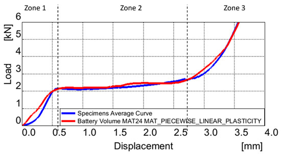
Figure 9.
Comparison between Battery Volume model MAT24 and real test Load vs. Displacement curve.

Table 3.
Battery volume simulation results.
In the actual response curve in the elastic region, designated as Zone 1, the termination of elastic deformation occurs at 0.6 mm press displacement after the initial contact with the battery, registering a force of 2.1 kN and a stiffness of 3.56 kN/mm. Observing Figure 9, it is discerned that the MAT24 battery volume force curve demonstrates a commendable alignment with the actual curve, but with a more linear behavior. However, comparative analysis, as delineated in Table 3, also reveals an analytical view of the elastic region with no error noted in the values.
Within the plastic deformation zone, denoted as Zone 2, specific metrics characterize the deformation behavior. The displacement in this region extends to 2.7 mm, resulting in a maximum end force of 2.67 kN and a stiffness of 0.98 kN/mm. Figure 9 visually indicates a favorable alignment between the force curve and the MAT24 battery volume model. In a quantitative assessment, the MAT24 battery volume model exhibits a peak end force of 2.64 kN with a 1.1% error, and a stiffness of 0.97 kN/mm, reflecting a small 1% discrepancy.
In the densification zone, denoted as Zone 3, a controlled displacement limit of 3.5 mm was imposed to facilitate the calculation of densification rates. Key parameters considered in this context include the initiation point and the subsequent rate of densification. In the actual model, densification commences at 2.7 mm, exhibiting a stiffness of 1.57 kN/mm. The MAT24 battery volume model indicates a stiffness of 1.57 kN/mm, reflecting no analytical deviation. The alignment between the curves during the densification phase is evident in Figure 9.
In the examination of battery Jelly Roll deformation, as in the battery volume model, specific focus is directed towards the compression behavior observed in the alignment of force curves (Figure 10) and analytical values (Table 4).
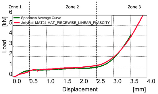
Figure 10.
Comparison between MAT24 jelly roll volume and real test, Load vs. Displacement curve.

Table 4.
Jelly roll volume simulation results.
In the elastic region (Zone 1), termination of elastic deformation occurs at 0.5 mm displacement, with a force of 0.6 kN and a stiffness of 1.2 kN/mm in the actual model. Notably, the MAT24 Jelly Roll volume model demonstrates commendable alignment with the actual curve. However, comparative analysis reveals that the model registers a force of 0.6 kN and a stiffness of 1.2 kN/mm, resulting in a no difference in force and stiffness.
Transitioning to the plastic deformation zone (Zone 2), displacement extends to 2.5 mm, resulting in a maximum end force of 0.99 kN and a stiffness of 0.39 kN/mm. Figure 10 visually indicates favorable alignment between the force curve and the MAT24 Jelly Roll volume model. However, quantitatively, the model displays values of a peak end force of 1.16 kN, a 17% error, and a stiffness of 0.46 kN/mm, a 17.9% discrepancy. A potential enhancement for future versions of the model would be to introduce more piecewise points within the densification zone. This would allow for a finer resolution of the material’s response during this critical phase, leading to better representation of the compaction process and increased accuracy.
In the densification zone (Zone 3), with a displacement of 3.5 mm, densification commences at 2.5 mm in the actual model, at a peak force of 4, with a stiffness of 1.14 kN/mm. The MAT24 Jelly Roll volume model has a peak force of 3.98, with a 0.5% error, accompanied by a stiffness of 1.13 kN/mm, reflecting 0.8% deviation. This good alignment of the curves in Zone 2 and 3 can also be seen in Figure 10.
When analyzing the Jelly Roll volume alongside the battery case model, particularly in Zone 1, which denotes the elastic region, distinct areas of elastic deformation become evident. The battery case exhibits higher stiffness initially, followed by a combination of Jelly Roll elasticity and case plasticity, as seen in Figure 11. This conclusion is not seen in the analytical results presented in Table 5 because, in cases of high deformation, the point of the force and displacement at the beginning of the plastic area is in focus.
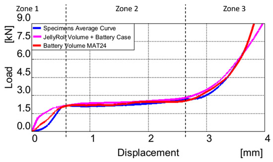
Figure 11.
Comparison between battery models and real test, Load vs. Displacement curve.

Table 5.
Jelly roll volume with battery case simulation results.
The comparison between various modeling approaches for the battery can be elucidated through the examination of Figure 11 and Figure 12.
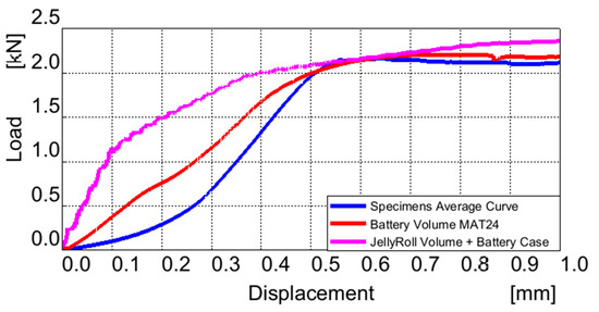
Figure 12.
Comparison between battery models elastic zone and real test, Load vs. Displacement curve.
Figure 12 suggests that the elasticity of the battery volume model aligns more closely with the actual curve in the elastic zone. This can be attributed to the simplified definition of material properties within a homogeneous volume model compared to the complexities involved in modeling materials for heterogeneous models. The deviations observed in the plastic region of the model are also influenced by the interaction with the battery case, though the case tends to reduce these discrepancies to 8.6% and 9.1%, respectively.
3.4. Model Sensibility Test
To ensure the model’s validity and applicability across different configurations, a sensitivity analysis was performed on a battery model composed of a jelly roll volume and its protective case. The analysis involved scaling the plastic strain and case thickness to observe how these modifications affect the densification process and the load curve.
When the plastic strain was scaled down by 10% and 20%, the densification occurred at lower deformations, as expected. Specifically, the initial point of densification shifted from 2.7 mm (original) to 2.5 mm and 2.3 mm, respectively. This indicates that reducing plastic strain sensitivity decreases the deformation required for densification to begin, altering the material response during high compression loads (Figure 13).
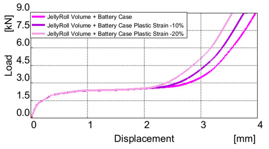
Figure 13.
Sensibility test of the Jelly Roll plastic strain piecewise parameters.
For the case thickness, scaling it down to half, which is representative of a thinner, commercially available Li-ion cell casing, resulted in a nearly halved load curve, reflecting the lower force resistance of the thinner case. Conversely, doubling the case thickness led to an exponential increase in force resistance, with the load curve scaling nearly threefold. This notable effect can be seen in the elastic region, where the increased thickness led to the elasticity of the case having a higher weight in the elasticity of the battery, as shown in Figure 14. These sensitivity tests highlight how both plastic strain and casing thickness directly influence the battery’s overall mechanical behavior under compression.
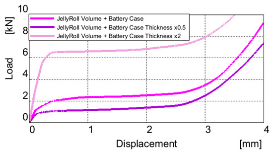
Figure 14.
Sensibility test of the case thickness.
4. Conclusions
The Finite Element Method (FEM) model is employed in this study of LS Dyna MAT24 (MAT_PIECEWISE_LINEAR_PLASTICITY). Calibration of these materials is achieved through a meticulous comparison with the force curve obtained from the real-life compression tests. The real-life compression experiments are conducted on three battery cell specimens, with the cap removed, and two jelly rolls. The force curve obtained from these experiments delineates three discernible states: an initial elastic response, a plastic deformation plateau, and a subsequent phase marked by rapid densification. Notably, the model is represented as a single entity, homogenizing the entire battery structure into solids. The LS DYNA material MAT24 (MAT_PIECEWISE_LINEAR_PLASTICITY) is calibrated meticulously to replicate the experimentally obtained force curve. This calibration process ensures that the FEM model accurately reflects the mechanical behavior observed in the real-life compression tests.
MAT24 proves invaluable in defining suitable materials for both the entire battery volume and the Jelly Roll component. The effectiveness of the Jelly Roll model is further validated by its robust performance when integrated with the battery case, demonstrating its practical utility. The validity of the model is further strengthened by the predictable sensibility study of the plastic parameters and the variation of the case thickness.
Suggestions for future work should focus on incorporating more experimental data, particularly under dynamic load conditions, where the behavior of the elastic, plastic, and failure zones can vary significantly. Dynamic testing would provide a more comprehensive understanding of how the material behaves across different strain rates, especially in high-impact scenarios. Using these experimental insights, the MAT24 material model could be refined by introducing strain rate-dependent parameters, which would enhance the accuracy of the battery deformation predictions. Without such adjustments, the model risks defaulting to worst-case deformation scenarios in case of high-impact simulations. Another valuable direction would be to reintroduce the battery caps in the model and investigate load cases from the axial direction to assess anisotropy across the entire battery. Additionally, integrating the model into a full vehicle crash simulation would allow for evaluating its performance in a holistic crash environment, providing insights into how the battery pack responds when subjected to real-world, complex loading, vehicle crash dynamics. In conclusion, the comprehensive comparison between the experimentally derived load-displacement curve of a uni-axial compression test on the 18650 Li-ion battery and its simulated counterparts provides robust insights across three distinct mechanical response zones. The piecewise approach in analyzing the curves might overlook some details in the elastic zone; however, the focus of this model is primarily on predicting behavior under high deformation conditions, plastic zone and densification, which are more critical for assessing crashworthiness and safety in scenarios involving large impacts or compressive forces. The overall overlaying of curves, as depicted in Figure 9, Figure 10 and Figure 11, reveals a comparable profile between the simulated model and the actual test data.
Author Contributions
Conceptualization: A.D.M. and M.C.D.; methodology: M.C.D.; software: A.D.M.; validation: A.D.M. and M.C.D.; formal analysis: M.C.D.; investigation: A.D.M. and M.C.D.; resources: A.D.M. and M.C.D.; data curation: M.C.D.; writing—original draft preparation: A.D.M.; writing—review and editing: M.C.D.; visualization: A.D.M.; supervision: M.C.D. All authors have read and agreed to the published version of the manuscript.
Funding
This research received no external funding.
Data Availability Statement
The data presented in this study are available in this manuscript.
Conflicts of Interest
The authors declare no conflicts of interest.
References
- Liu, B.; Jia, Y.; Yuan, C.; Wang, L.; Gao, X.; Yin, S.; Xu, J. Safety issues and mechanisms of lithium-ion battery cell upon mechanical abusive loading: A review. Energy Storage Mater. 2020, 24, 85–112. [Google Scholar] [CrossRef]
- Gong, C.; Liu, J.; Han, Y.; Hu, Y.; Yu, H.; Zeng, R. Safety of electric vehicles in crash conditions: A review of hazards to occupants, regulatory activities, and technical support. IEEE Trans. Transp. Electrif. 2021, 8, 3870–3883. [Google Scholar] [CrossRef]
- Liu, B.H.; Yin, S.; Xu, J. Integrated computation model of lithium-ion battery subject to nail penetration. Appl. Energy 2016, 183, 278–289. [Google Scholar] [CrossRef]
- Vyroubal, P.; Kazda, T. Finite element model of nail penetration into lithium ion battery. J. Energy Storage 2018, 20, 451–458. [Google Scholar] [CrossRef]
- Xia, Y.; Wierzbicki, T.; Sahraei, E.; Zhang, X. Damage of cells and battery packs due to ground impact. J. Power Sources. 2014, 267, 78–97. [Google Scholar] [CrossRef]
- Ruiz, V.; Pfrang, A.; Kriston, A.; Omar, N.; van den Bossche, P.; Boon-Brett, L. A review of international abuse testing standards and regulations for lithium ion batteries in electric and hybrid electric vehicles. Renew. Sustain. Energy Rev. 2018, 81, 1427–1452. [Google Scholar] [CrossRef]
- Kotak, B.; Kotak, Y.; Brade, K.; Kubjatko, T.; Schweiger, H.-G. Battery crush test procedures in standards and regulation: Need for augmentation and harmonization. Batteries 2021, 7, 63. [Google Scholar] [CrossRef]
- Lai, W.-J.; Ali, M.Y.; Pan, J. Mechanical behavior of representative volume elements of lithium-ion battery cells under compressive loading conditions. J. Power Sources 2014, 245, 609–623. [Google Scholar] [CrossRef]
- Ali, M.Y.; Lai, W.-J.; Pan, J. Computational models for simulations of lithium-ion battery cells under constrained compression tests. J. Power Sources 2013, 242, 325–340. [Google Scholar] [CrossRef]
- Xu, J.; Liu, B.; Wang, L.; Shang, S. Dynamic mechanical integrity of cylindrical lithium-ion battery cell upon crushing. Eng. Fail. Anal. 2015, 53, 97–110. [Google Scholar] [CrossRef]
- Sheikh, M.; Elmarakbi, A.; Rehman, S. A combined experimental and simulation approach for short circuit prediction of 18650 lithium-ion battery under mechanical abuse conditions. J. Energy Storage 2020, 32, 101833. [Google Scholar] [CrossRef]
- Avdeev, I.; Gilaki, M. Structural analysis and experimental characterization of cylindrical lithium-ion battery cells subject to lateral impact. J. Power Sources 2014, 271, 382–391. [Google Scholar] [CrossRef]
- Jantscher, K.; Breitfuß, C.; Miklau, M.; Ismail, K.; Dobusch, P. Virtual Detection of Mechanically Induced Short Circuits in a Cylindrical Lithium-Ion Battery Cell Based on Finite Element Simulation. Batteries 2021, 7, 79. [Google Scholar] [CrossRef]
- Madani, S.S.; Schaltz, E.; Kær, S.K. Characterization of the Compressive Load on a Lithium-Ion Battery for Electric Vehicle Application. Machines 2021, 9, 71. [Google Scholar] [CrossRef]
- Hahn, A.; Doose, S.; Saathoff, D.; Kwade, A. Effect of External Compression on the Thermal Runaway of Lithium-Ion Battery Cells during Crush Tests: Insights for Improved Safety Assessment. Batteries 2023, 9, 404. [Google Scholar] [CrossRef]
- Zhu, J.; Wierzbicki, T.; Li, W. A review of safety-focused mechanical modeling of commercial lithium-ion batteries. J. Power Sources 2018, 378, 153–168. [Google Scholar] [CrossRef]
- Raffler, M.; Sevarin, A.; Ellersdorfer, C.; Heindl, S.F.; Breitfuss, C.; Sinz, W. Finite element model approach of a cylindrical lithium ion battery cell with a focus on minimization of the computational effort and short circuit prediction. J. Power Sources 2017, 360, 605–617. [Google Scholar] [CrossRef]
- Abada, S.; Marlair, G.; Lecocq, A.; Petit, M.; Sauvant-Moynot, V.; Huet, F. Safety focused modeling of lithium-ion batteries: A review. J. Power Sources 2016, 306, 178–192. [Google Scholar] [CrossRef]
- Abedini, M.; Zhang, C. Performance assessment of concrete and steel material models in ls-dyna for enhanced numerical simulation, a state of the art review. Arch. Comput. Methods Eng. 2021, 28, 2921–2942. [Google Scholar] [CrossRef]
- Sarkar, A.; Shrotriya, P.; Chandra, A. Modeling of separator failure in lithium-ion pouch cells under compression. J. Power Sources 2019, 435, 226756. [Google Scholar] [CrossRef]
- Muresanu, A.D.; Dudescu, M.C. Numerical and experimental evaluation of a battery cell under impact load. Batteries 2022, 8, 48. [Google Scholar] [CrossRef]
- Szabo, I.; Scurtu, L.I.; Raboca, H.; Mariasiu, F. Topographical Optimization of a Battery Module Case That Equips an Electric Vehicle. Batteries 2023, 9, 77. [Google Scholar] [CrossRef]
Disclaimer/Publisher’s Note: The statements, opinions and data contained in all publications are solely those of the individual author(s) and contributor(s) and not of MDPI and/or the editor(s). MDPI and/or the editor(s) disclaim responsibility for any injury to people or property resulting from any ideas, methods, instructions or products referred to in the content. |
© 2024 by the authors. Licensee MDPI, Basel, Switzerland. This article is an open access article distributed under the terms and conditions of the Creative Commons Attribution (CC BY) license (https://creativecommons.org/licenses/by/4.0/).