Article

Dynamics of Non-Magnetic Droplets and Bubbles in Magnetic Fluids in Microfluidic Channels under the Influence of a Magnetic Field

Department of Nanotechnology, Microelectronics, General and Applied Physics, Faculty of Natural Sciences, Southwest State University, 50 Let Oktyabrya Street, 94, Kursk 305040, Russia
*
Author to whom correspondence should be addressed.
Magnetochemistry 2023, 9(8), 197; https://doi.org/10.3390/magnetochemistry9080197
Submission received: 31 May 2023 / Revised: 30 June 2023 / Accepted: 17 July 2023 / Published: 1 August 2023
(This article belongs to the Section Magnetic Field)

Abstract

:
The microfluidics of magnetic fluids is gaining popularity due to the possibility of the non-contact control of liquid composite systems using a magnetic field. The dynamics of non-magnetic droplets and gas bubbles in magnetic fluids were investigated for various configurations of magnetic fields, coatings, and channel geometries, as well as the rate of component supply and their physical properties. Optimal regimes for forming droplet and bubble flows were determined. The mechanism for non-contact control of the size of droplets and bubbles using a magnetic field is proposed in this article. The dependences of the sizes of non-magnetic inclusions in magnetic liquids on the continuous phase flow rate and the displacement of magnets were obtained. The obtained dependences of the volume of non-magnetic inclusions on the flow rate of the continuous phase follow the classic dependences. Changing the size of air bubbles can be achieved by shifting the magnet from −5 mm to +2 mm. The ratio of the maximum and minimum breakaway inclusion varies from 5 to 2 depending on the flow rates of the continuous phase. The range of changing the size of oil droplets with the displacement of magnets is from 1.1 to 1.51. These studies show how, with the help of various mechanisms of influence on microfluidic flows, it is possible to control the size of bubbles and droplets forming in microchannels. The obtained data can be applied for controlled microfluidic dosing and counting devices.

1. Introduction

Magnetic fluids are a unique active material that combine fluidity and magnetic properties [1]. It is a colloidal solution of magnetic nanoparticles coated with a surfactant and dispersed in a carrier liquid [2]. Magnetic fluids are the first artificially synthesized nanomaterial [3]. They have been the object of active research for 60 years and provide a wide scientific field for both experimenters [4] and theorists [5,6] due to the unique interaction of their microstructure, macroscopic properties, and the dynamics of colloid volumes under various combinations of external influence. The properties of these materials can be controlled by a magnetic field of various strengths since the magnetic properties of magnetic fluids strongly depend on external influences. Magnetic colloids are widely used in various technical devices: shock absorbers [7,8], separators [9], sensors [10], and many other devices. Despite a significant period of research and implementation, over the past few years, there has been an exponential increase in the number of publications and patents related to magnetic fluids. This is due to the development of technologies for the synthesis of colloids with specific surfactants, the emergence of targeted drug delivery, and the development of microfluidic systems. In microfluidics, in which traditional methods of flow control do not work, magnetic fluids have revealed their potential for active control [11,12].
The magnetophoresis of micro- and nanoparticles in a liquid in a microchannel under the influence of various sources of magnetic fields was one of the first to be investigated [13,14,15]. The dynamics of magnetophoresis in a thin layer of magnetic fluid have been studied by scanning optical transparency with a laser beam [16,17] and the separation and focusing of magnetic and non-magnetic particles under the influence of magnetophoresis [18]. A combination of magnetophoretic and centrifugal forces for separation in a microfluidic chip [19] and a combination of magneto- and electrophoresis in a microfluidic chip have been used in many studies [20]. In the case when one of the phases contains magnetic particles in a microchannel under the influence of an inhomogeneous magnetic field, instability of the interphase boundary occurs and can be fixed by optical methods [21]. In addition to magnetophoresis, the manipulation of flows and particles can be carried out using electrophoresis. The process of mixing two liquids in a Y-type mixer has been investigated. The alternating current electric field, which was created by two copper strips for each channel entrance, acted on the system [22].
The magnetic field source is the most important component of magnetofluidic microfluidic systems [23]. Permanent magnets [24], electromagnets [25], or their combinations [26] are used for magnetic manipulations in microfluidic systems. However, recently, there have been more and more works in which the phenomenon of magnetic levitation, “MagLev”, in an inhomogeneous magnetic field is used to separate non-magnetic objects: particles, droplets, and biological objects in a magnetic medium [27,28]. A distinctive feature of this approach is the absence of specific surfactants. Separation and manipulation occur depending on the density of non-magnetic inclusions [13].
Manipulation of liquid multiphase systems has been singled out in a separate direction: drip microfluidics, which considers the processes of the formation, control, and dynamics of emulsions of various systems [29,30]. The droplet size is regulated mainly by changing the flow rate [31]. The use of a magnetic fluid makes it possible to add a variant of active droplet formation using an external magnetic field [32]. Drop microfluidics using magnetic fluids remains an insufficiently studied area [33] despite significant prospects for application, primarily targeted drug delivery [34,35] using active drops [36,37] and multilayer emulsions [38,39].
Various combinations of magnets are used in drop microfluidics setups with magnetic fluids [40]. A permanent magnet was used to create anisotropy of the magnetic moment in “polymer drops cured by UV radiation” with a built-in drop of magnetic liquid [41]. A theoretical model with a different configuration of electromagnets was considered in the work [42]. A variant of a microfluidic channel with wall-less magnetic confinement due to a magnetic fluid is known [43]. Such a configuration of an inhomogeneous magnetic field using magnetic levitation regions [44] creates prerequisites for the active control of droplet sizes using a magnetic field [45,46]. In previous works, we proposed a new mechanism for controlling the size of droplets that detach from a non-magnetic droplet levitating in a magnetic fluid [47]. However, when switching to the microfluidic scale, we faced significant difficulties: our experiments were carried out only with gas bubbles [48,49]. With the introduction of a non-magnetic fluid phase in most modes, we obtained a jet flow [50]. The reason for this is the influence of the microfluidic chip’s walls and interfacial tension, which was not taken into account in these studies.
The aim of this work is to study the dynamics of the separation of bubbles and oil droplets in a biocompatible water-based magnetic fluid with various surfactants in microfluidic channels of various configurations in a magnetic field created by annular permanent magnets.

2. Materials and Methods

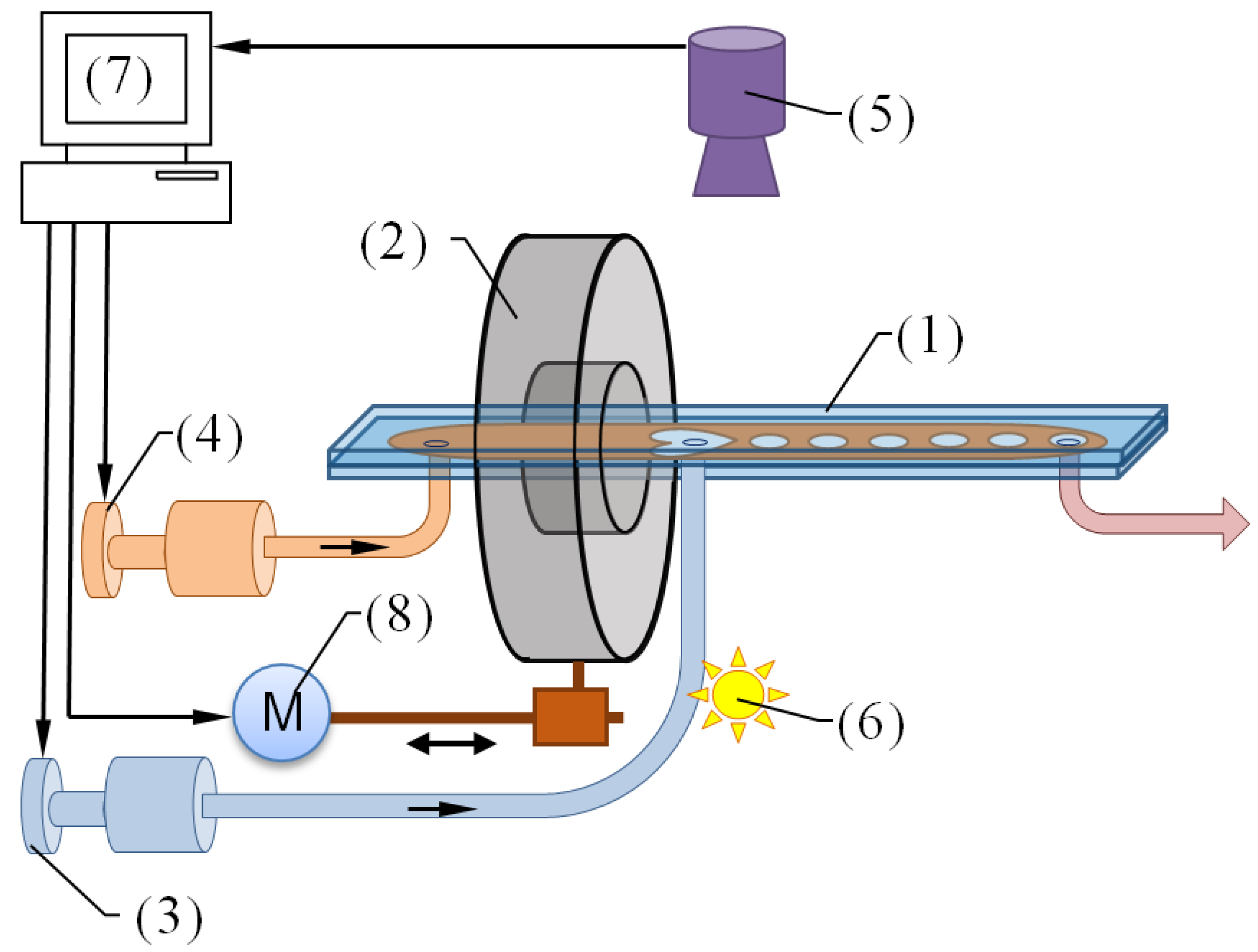
2.1. Experimental Setup
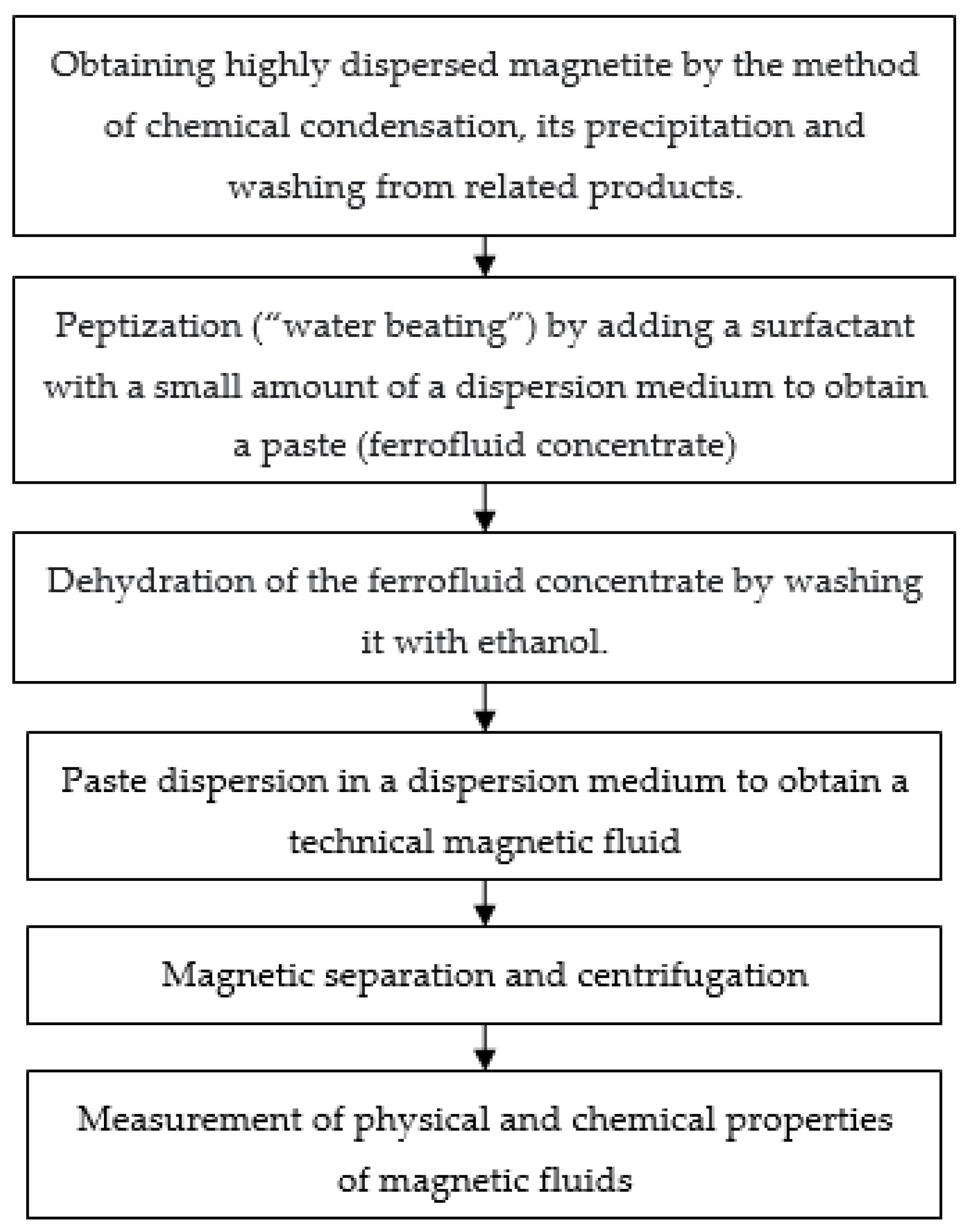
The block diagram of the experimental setup is shown in Figure 1. The microfluidic chips were manufactured using glass–parafilm–glass sandwich technology [50,51]. The syringe pump was made using an Ender 3D printer (Creator: Creativity, Shenzhen, China) [52].
The microfluidic chip (1) is fixed using a system of non-magnetic fasteners and located parallel to the axis of the ring permanent magnet (2). A dual-channel syringe pump (3, 4) is used for the injection of continuous and dispersed phases into the chip. The dynamics of the multiphase system were recorded by a microscope (the video recordings’ resolution is equal to 1280 × 960, 30 fps) (5) in the transmitted light emitted by the light source (6). A computer (7) controls the syringe pump. The magnet (2) was moved using a mechatronic actuator (8), made independently from the z-axis of the Ender 3D printer, which was controlled by a computer (7). The video stream from the microscope (5) was transferred to the computer (7), where the files were further processed in the NI Lab View program.
We used two types of NdFeB permanent magnets. Magnet 1: its outer diameter is 60 mm, its inner diameter is 24 mm, its thickness is 10 mm, and its magnetic field strength is 214 kA/m; magnet 2: its outer diameter is 50 mm, its inner diameter is 25 mm, its thickness is 5 mm, and its magnetic field strength is 85 kA/m.
Magnet 1, in comparison with magnet 2, is characterized by larger geometric dimensions, as well as a larger value of the magnetic field strength on the surface of the magnet. A detailed simulation of the “magnetic vacuum” region for annular permanent magnets is shown in Figure 2.
The isolines in Figure 2 were determined using MATLAB’s built-in function for 2D data processing. A detailed procedure for modeling the “magnetic vacuum” region for annular permanent magnets is described in our previous papers [44,53].
The technology of manufacturing microfluidic devices based on sandwich structures and Parafilm M® film used in our research consists of several stages:
1.
Preparation of microfluidic chip layers:
-
Processing of slides with a solution of NaOH in 6% hydrogen peroxide to remove organic compounds from the glass surface;
-
Washing glasses with distilled water and drying them;
-
Producing a stencil of the required configuration from Parafilm M® film using the Gifttec MT365 cutting plotter (Creator: Gifttec, China). The stencil model was developed in the CorelDRAW program.
2.
Microfluidic chip assembly: A stencil cut from Parafilm® film is placed between two slides.
3.
Preheating of the heating plate IKA C-Mag HP 7 to 55 °C for uniform heat distribution.
4.
Sintering of the device for 10 min at a heating temperature of 55 °C.
5.
Gluing connectors to the inputs and outputs of a microfluidic chip.

2.2. Physical Properties of the Samples

We synthesized magnetic fluid (MF) based on magnetite stabilized with a double layer of surfactant and oleic acid + sodium oleate. Water was used as the carrier fluid. The studied magnetic colloid was synthesized by chemical condensation.
Chemical condensation of highly dispersed magnetite is the basis of this method:
2 FeCl 3   ×   6 H 2 O   +   FeSO 4   ×   7 H 2 O   +   8 NH 4 OH excess NH 4 OH Fe 3 O 4   +   6 NH 4 Cl   +   ( NH 4 ) 2 SO 4   +   23 H 2 O .
The technological scheme for the production of magnetic fluids is shown in Figure 3.
The physicochemical characteristics of the samples are presented in Table 1.

3. Results

Microfluidic chips of the “coaxial flow” configuration, samples of which are shown as №1 and №2 in Figure 4, were used to study the controlled dynamics of non-magnetic inclusions in a magnetic fluid. Microfluidic chips with “flow focusing junctions” configuration, which are shown as №3 in Figure 4, were also used to study the dynamics of liquid and gaseous non-magnetic inclusions in a magnetic fluid.
The filling of the MF is carried out through input 1, and the supply of the non-magnetic phase to the “magnetic vacuum” area is through input 2. The output of the multiphase mixture is carried out through connector 3.
The experiments were carried out both under the influence of an inhomogeneous magnetic field and without it. Video filming of the dynamics of the interface was carried out using a microscope in transmitted light. The dynamics of the breaking bubble were studied for different values of the flow velocity. The flow rate of the magnetic fluid varied in the range from 0.15 to 1.1 µL/s. Air was supplied at a rate of 0.18 µL/s for microfluidic device №1 and 0.37 µL/s for microfluidic device №2. The range of flow velocities was chosen based on the criterion of formation of a stable drip flow. Another criterion is the design features of the syringe pump, manufactured independently, the fraction of its pitch, and the volume of the syringe (2 mL).
The values of the flow velocities of the continuous phase (samples of magnetic liquids MF-1–MF-3) of the dispersed phase (air) and the corresponding Re numbers for this experiment are presented in Table 2.
The position of the permanent magnet changed during the experiment. The magnet was in the positions of −5; −2.5; 0; +1; and +2 mm. The gas flow rate was fixed. The process of bubble formation in microfluidic chips is shown in Figure 5, which shows the geometry of the “MF-air” interface in microchannels of various configurations.
Frames 1–3 show a change in the air cavity in the “magnetic vacuum” region. It can be seen how the supplied magnetic fluid gradually squeezes the upper part of the formation (frames 3 and 4) and then the air bubble is detached from the cavity of the frame (5) and its movement in the channel of the microfluidic chip (frame 6).
The obtained images were studied using a program developed in LabVIEW, in which the area and coordinates of the detached non-magnetic optically transparent inclusions were determined for various time points. The plots of the dependence of the size of the forming bubbles on the pumping speed and the movement of the annular permanent magnet relative to the axis of the channel are shown in Figure 6 and Figure 7 for microfluidic chip No. 1 with magnets No. 1 and No. 2, respectively. The dependences on the flow rate of the non-magnetic phase have a traditional character, coinciding with the plots presented in the works on microfluidics both without a magnetic field and in it. It can be seen from the plots that with an increase in the rate of supply of magnetic fluid to the microchannel, the size of the forming bubbles decreases, and the frequency of their generation increases. This dependence can be explained by a change in the hydrodynamic pressure on the volume of formation of inclusions, which increases with a decrease in the flow rate of the continuous phase, which leads to the earlier separation of air bubbles.
Dependences on the displacement of the magnet were obtained for the first time. It can be seen from the presented plots that the displacement of the magnet to the right leads to an increase in the size of gas bubbles by more than two times for concentrated samples of MF-1 and MF-2 and by 1.5 times for a diluted sample of MF-3 for both magnets. This change in the size of the breaking-off bubbles occurs at a constant flow rate of the continuous and dispersed phase, which creates prerequisites for the development of a new magnetic active external control method.
However, when the magnet is shifted to the right, a decrease first occurs, and then an increase in the size of the gas bubbles coming off, this can be explained by the occurrence of instabilities of the air–magnetic fluid interface under the influence of an inhomogeneous magnetic field.
To stabilize the flow, the configuration of microfluidic chip №2 was developed; the results of the study in this configuration are shown in Figure 8 and Figure 9.
It can be seen from the plots presented in Figure 8 and Figure 9 that the size of the escaping gas bubbles has decreased compared to the data presented in Figure 6 and Figure 7. The ratio of bubble sizes at the maximum displacement of the magnet to the left to the bubble size at the zero position remained within two for concentrated samples of MF-1, MF-2, and 1.5 times for a diluted sample of MF-3. When the magnet is shifted to the right, the bubble size decreases twice for the most concentrated sample MF-1, by 1.5 times for the sample MF-2, and by 20% for the most diluted sample MF-3.
These differences between the dependencies shown in Figure 6 and Figure 7 and the plots shown in Figure 8 and Figure 9 can be explained by the configuration of microfluidic chip №2, in which there is a separating horseshoe-shaped element from the film Parafilm M® (Figure 4). As a result, the interfacial boundary becomes more stable when the magnet is shifted to the right. At the same time, the hydrodynamic flow of the magnetic fluid becomes more focused, which leads to a decrease in the size of the gas bubbles.
In Figure 9, the dependences of the size of the gas bubbles on the flow rate of the continuous magnetic phase (left) and on the displacement of the magnet (right) are represented. It can be seen that the size of the bubbles simultaneously depends on these parameters. For the maximum liquid flow rate q1 = 1.1 µL/s, the ratio of the maximum and minimum bubble size is 2 when the magnet is displaced. The maximum size of inclusions is almost four times larger than the minimum size of the bubble with minimum consumption of the magnetic colloid q1 = 0.15 µL/s. Thus, the magnetic field, when it is displaced, has a greater effect on the size of inclusions at a minimum value of the continuous phase flow rate than with a powerful liquid flow. This is due to the action of magnetic forces, which have a greater effect on the change in the volume of bubbles at low currents than at high rates of magnetic fluid supply.
It was not possible to achieve the formation of a bubble flow in microfluidic chip №3 (Figure 4). This is explained by the influence of the orientation of the magnetic field and the hydrodynamic flow. In this case, the flow of the magnetic field is perpendicular to the axis of the ring magnet, as a result of which higher gas pressure is required to break the magnetic fluid bridge. At the moment of rupture, a large portion of the gas is injected into the microfluidic channel, squeezing the magnetic fluid out of it. We have obtained an inverse result in experiments on the study of the dynamics of oil droplets in a water-based ferrofluid in a magnetic field. A droplet flow was formed only in microfluidic chip No. 3 with “flow focusing junctions”. In microfluidic chips №1 and №2, under the influence of an inhomogeneous magnetic field, the flow had a jet character.
The experiments were carried out with drops of mineral oil supplied as a dispersed phase. Physical parameters of the oil: viscosity 19.0 µPa∙s and density 858.0 kg/m3. Drip flows did not occur when pure liquids were used. The Twin-80 surfactant was added to the ferrofluid samples (the mass fraction of the substance is 5%) to improve droplet formation. Twin-80 (polysorbate) is a non-ionic surfactant used to create direct emulsions. The hydrophilic–lipophilic balance of the substance is 15–15.6. The experiments were carried out with samples of MF-2 and MF-3. For a microfluidic device with configuration №3, studies were carried out using two permanent ring magnets that move relative to the dispersed phase supply connector by +1, 0, −1, −2, −3, −4, and −5 mm. The flow rates of the magnetic phase q1 for the MF-2 sample are 0.74, 1.10, 1.47, and 1.84 μL/s. The mineral oil flow rate remains constant at 0.04 µL/s. The values of the flow velocities of the continuous phase (samples of magnetic liquids MF-2–MF-3) of the dispersed phase (oil) and the corresponding Re numbers for this experiment are presented in Table 3.
Figure 10 shows the formation of mineral oil droplets in a sample of magnetic fluid MF-2 under the action of the magnetic field of magnet 1 (left) and magnet 2 (right) at different feed rates of the continuous phase q1. In this case, the magnets are in position 0 relative to the non-magnetic phase supply connector.
It is clearly visible from the frames that with an increase in the speed of the magnetic fluid supply, the size of the oil droplets decreases. Also, under the action of a stronger magnetic field for magnet 1, the drops of a non-magnetic inclusion have a more elongated shape in comparison with the shape of the drops under the action of the magnetic field of magnet 2.
The plots of the dependence of the size of the forming oil drops on the pumping speed and the movement of the annular permanent magnet relative to the axis of the channel are shown in Figure 11 for microfluidic chip No. 1 with magnets No. 1 and No. 2.
Air is a more compressible medium than any liquid. As shown in the plots on the left-hand side of Figure 11, the size of the formed bubbles decreases with the increase in the feed rate of the continuous phase. From the plots presented in Figure 6, Figure 7, Figure 8 and Figure 9, the largest bubble value was observed at the maximum distance of the magnets from the phase mixing zone. However, it can be seen from the plots on the right-hand side (Figure 11) that oil droplets of the maximum volume were formed at the zero position for magnet 1 and at the −1 position for magnet 2. When the magnets were shifted to the right and to the left, the size of the inclusions gradually decreased since the magnetic vacuum area shifted relative to the mixing zone of the liquids.
For the less concentrated MF-3 sample, the dependence on flow rates could not be obtained, since oil jet flow was observed at MF pumping rates of 0.74, 1.10, and 1.47 µL/s. A droplet flow was obtained at a flow rate of 1.84 µL/s. Plots of the dependence of the droplet volume on the flow rate and the displacement of magnets are shown in Figure 12.
Figure 12 shows that the size of the mineral oil droplets gradually decreases as the magnets shift to the right. The volume of the drop decreases by 29% when moving magnet 1 and by 12% when moving magnet 2.

4. Conclusions

The behavior of gas bubbles and non-magnetic oil droplets in a water-based magnetic fluid was considered in microchannels of various shapes. The experiments were carried out under the influence of an inhomogeneous magnetic field created by ring permanent magnets. Three configurations of microfluidic chips were developed in this work: with hydrodynamic focusing only by a magnetic field, hydrodynamic focusing by a magnetic field and channel configuration, and flow-focusing junctions.
It was shown that the formation of a bubble flow in a magnetic fluid in a non-uniform magnetic field was achieved in microfluidic chips with hydrodynamic focusing. Droplet flow, on the contrary, was observed only in chips with flow-focusing junctions.
The dependences of the size of detached bubbles and non-magnetic drops on the flow rate of the magnetic fluid and the displacement of the magnet from the equilibrium position were obtained in the work.
The supply of a non-magnetic phase to the region of the magnetic vacuum makes it possible to achieve stable modes at all concentrations of the magnetic fluid and configurations of the magnetic field.
It was shown that for all combinations of the magnetic field and magnetic fluid concentrations, the size of the bubble or drop decreases as the flow rate of the magnetic fluid q1 increases.
When the concentration of the magnetic fluid changes and the magnet is displaced, the size of the bubble or drop decreases, which makes it possible to organize non-contact control using a magnetic field, which can be used in counters and dispensers in microfluidics.

Author Contributions

Conceptualization, E.S. and P.R.; methodology, E.S., D.K., A.V. and P.R.; synthesis of magnetic fluids, I.S. (Irina Shabanova); software, P.R.; validation, E.S., P.R. and D.K.; formal analysis, I.S. (Irina Sutarina) and D.K.; investigation, I.S. (Irina Sutarina) and E.S.; resources, E.S.; data curation, E.S. and D.K.; writing—original draft preparation, E.S.; writing—review and editing, P.R.; visualization, E.S. and A.V.; supervision, P.R.; project administration, P.R.; funding acquisition, P.R. All authors have read and agreed to the published version of the manuscript.

Funding

The research was carried out at the expense of the grant of the Russian Science Foundation No. 22-22-00311, https://rscf.ru/project/22-22-00311/ (accessed on 12 December 2022) (funder Russian Science Foundation).

Institutional Review Board Statement

Not applicable.

Informed Consent Statement

Not applicable.

Data Availability Statement

Not applicable.

Conflicts of Interest

The authors declare no conflict of interest.

References

  1. Rosensweig, R.E. Ferrohydrodynamics; Courier Corporation: Chelmsford, MA, USA, 1984; p. 348. [Google Scholar]
  2. Socoliuc, V.; Avdeev, M.V.; Kuncser, V.; Turcu, R.; Tombácz, E.; Vékás, L. Ferrofluids and bio-ferrofluids: Looking back and stepping forward. Nanoscale 2022, 14, 4786–4886. [Google Scholar] [CrossRef] [PubMed]
  3. Pappell, S.S. MPK Low Viscosity Magnetic Fluid Obtained by the Colloidal Suspension of Magnetic Particles. U.S. Patent No. 3215572, 2 November 1965. [Google Scholar]
  4. Philip, J. Magnetic nanofluids: Recent advances, applications, challenges, and future directions. Adv. Colloid Interface Sci. 2022, 311, 102810. [Google Scholar] [CrossRef] [PubMed]
  5. Elsaady, W.; Oyadiji, S.O.; Nasser, A. A review on multi-physics numerical modelling in different applications of magnetorheological fluids. J. Intell. Mater. Syst. Struct. 2020, 31, 1855–1897. [Google Scholar] [CrossRef]
  6. Solovyova, A.Y.; Elfimova, E.A.; Ivanov, A.O.; Camp, P.J. Modified mean-field theory of the magnetic properties of concentrated, high-susceptibility, polydisperse ferrofluids. Phys. Rev. E 2017, 96, 052609. [Google Scholar] [CrossRef] [Green Version]
  7. Li, Y.; Han, P.; Li, D.; Chen, S.; Wang, Y. Typical dampers and energy harvesters based on characteristics of ferrofluids. Friction 2023, 11, 165–186. [Google Scholar] [CrossRef]
  8. Kazakov, Y.B.; Morozov, N.A.; Nesterov, S.A. Development of models of the magnetorheological fluid damper. J. Magn. Magn. Mater. 2017, 431, 269–272. [Google Scholar] [CrossRef]
  9. Kazakov, Y.B.; Filippov, V.A. Calculation of the performance of the electromagnetic magnetic fluid separator non-magnetic materials. IOP Conf. Ser. Mater. Sci. Eng. 2020, 950, 012003. [Google Scholar] [CrossRef]
  10. Lagutkina, D.Y.; Saikin, M.S. The research and development of inclination angle magnetic fluid detector with a movable sensing element based on permanent magnets. J. Magn. Magn. Mater. 2017, 431, 149–151. [Google Scholar] [CrossRef]
  11. Pamme, N. Magnetism and microfluidics. Lab Chip 2006, 6, 24–38. [Google Scholar] [CrossRef]
  12. Xuan, X. Recent advances in continuous-flow particle manipulations using magnetic fluids. Micromachines 2019, 10, 744. [Google Scholar] [CrossRef] [Green Version]
  13. Nam-Trung, N. Micro-magnetofluidics: Interactions between magnetism and fluid flow on the microscale. Microfluid. Nanofluidics 2012, 12, 1–16. [Google Scholar] [CrossRef] [Green Version]
  14. Munaz, A.; Shiddiky, M.J.A.; Nguyen, N.T. Recent advances and current challenges in magnetophoresis based micro magnetofluidics. Biomicrofluidics 2018, 12, 031501. [Google Scholar] [CrossRef] [PubMed]
  15. Alnaimat, F.; Dagher, S.; Mathew, B.; Hilal-Alnqbi, A.; Khashan, S. Microfluidics based magnetophoresis: A review. Chem. Rec. 2018, 18, 1596–1612. [Google Scholar] [CrossRef] [PubMed]
  16. Ivanov, A.S.; Pshenichnikov, A.F. Dynamics of magnetophoresis in dilute magnetic fluids. Magnetohydrodynamics 2010, 2, 125–136. [Google Scholar] [CrossRef] [Green Version]
  17. Ivanov, A.S.; Pshenichnikov, A.F. Magnetophoresis and diffusion of colloidal particles in a thin layer of magnetic fluids. J. Magn. Magn. Mater. 2010, 322, 2575–2580. [Google Scholar] [CrossRef]
  18. Zhou, R.; Wang, C. Multiphase ferrofluid flows for micro-particle focusing and separation. Biomicrofluidics 2016, 10, 034101. [Google Scholar] [CrossRef] [Green Version]
  19. Kirby, D.; Siegrist, J.; Kijanka, G.; Zavattoni, L.; Sheils, O.; O’Leary, J.; Ducrée, J. Centrifugo-magnetophoretic particle separation. Microfluid. Nanofluidics 2012, 13, 899–908. [Google Scholar] [CrossRef]
  20. Issadore, D.; Franke, T.; Brown, K.A.; Hunt, T.P.; Westervelt, R.M. High-voltage dielectrophoretic and magnetophoretic hybrid integrated circuit/microfluidic chip. J. Microelectromech. Syst. 2009, 18, 1220–1225. [Google Scholar] [CrossRef] [Green Version]
  21. Kichatov, B.; Korshunov, A.; Sudakov, V.; Gubernov, V.; Golubkov, A.; Kiverin, A.; Nastulyavichus, A.; Kudryashov, S. Pattern formation and collective effects in the process of the motion of magnetic nanomotors in narrow channels. Phys. Chem. Chem. Phys. 2023, 25, 11780–11788. [Google Scholar] [CrossRef]
  22. Mohammad Jafarpour, A.; Rostamzadeh Khosroshahi, A.; Hanifi, M.; Sadegh Moghanlou, F. Experimental study on the performance of a mini-scale Y-type mixer with two liquid metal-enabled pumps. Phys. Fluids 2022, 34, 112110. [Google Scholar] [CrossRef]
  23. Xiong, Q.; Song, X.; Yang, M.; Zhou, L.; Li, Z.; Zhu, X.; Zhi, L. Future trends in magnetic source device design for magnetic targeted drug delivery system. Int. J. Appl. Electromagn. Mech. 2021, 67, 261–277. [Google Scholar] [CrossRef]
  24. Yapici, M.K.; Zou, J. Permalloy-coated tungsten probe for magnetic manipulation of micro droplets. Microsyst. Technol. 2008, 14, 881–891. [Google Scholar] [CrossRef]
  25. Smistrup, K.; Tang, P.T.; Hansen, O.; Hansen, M.F. Microelectromagnet for magnetic manipulation in lab-on-a-chip systems. J. Magn. Magn. Mater. 2006, 300, 418–426. [Google Scholar] [CrossRef]
  26. Timonen, J.V.I.; Grzybowski, B.A. Tweezing of Magnetic and Non-Magnetic Objects with Magnetic Fields. Adv. Mater. 2017, 29, 1603516. [Google Scholar] [CrossRef]
  27. Ge, S.; Nemiroski, A.; Mirica, K.A.; Mace, C.R.; Hennek, J.W.; Kumar, A.A.; Whitesides, G.M. Magnetic levitation in chemistry, materials science, and biochemistry. Angew. Chem. Int. Ed. 2020, 59, 17810–17855. [Google Scholar] [CrossRef]
  28. Zhu, G.-P.; Wang, Q.-Y.; Ma, Z.-K.; Wu, S.-H.; Guo, Y.-P. Droplet Manipulation under a Magnetic Field: A Review. Biosensors 2022, 12, 156. [Google Scholar] [CrossRef] [PubMed]
  29. Teh, S.-Y.; Lin, R.; Hung, L.-H.; Lee, A.P. Droplet microfluidics. Lab Chip 2008, 8, 198–220. [Google Scholar] [CrossRef]
  30. Jeyhani, M.; Navi, M.; Chan, K.W.Y.; Kieda, J.; Tsai, S.S.H. Water-in-water droplet microfluidics: A design manual. Biomicrofluidics 2022, 16, 061503. [Google Scholar] [CrossRef]
  31. Huang, B.; Xie, H.; Li, Z. Microfluidic Methods for Generation of Submicron Droplets: A Review. Micromachines 2023, 14, 638. [Google Scholar] [CrossRef]
  32. Zhu, P.; Wang, L. Passive and active droplet generation with microfluidics: A review. Lab Chip 2017, 17, 34–75. [Google Scholar] [CrossRef]
  33. Al-Hetlani, E.; Amin, M.O. Continuous magnetic droplets and microfluidics: Generation, manipulation, synthesis and detection. Microchim. Acta 2019, 186, 55. [Google Scholar] [CrossRef]
  34. Li, Q.; Feng, F.; Xu, M.; Liu, Y.; Li, M.; Feng, X.; Wang, X.; Yao, L. Multifunctional liquid microrobots based on paramagnetic microdroplets. Cell Rep. Phys. Sci. 2023, 4, 101279. [Google Scholar] [CrossRef]
  35. Fan, X.; Sun, M.; Sun, L.; Xie, H. Ferrofluid droplets as liquid microrobots with multiple deformabilities. Adv. Funct. Mater. 2020, 30, 2000138. [Google Scholar] [CrossRef]
  36. Liu, X.; Kent, N.; Ceballos, A.; Streubel, R.; Jiang, Y.; Chai, Y.; Kim, P.Y.; Forth, J.; Hellman, F.; Shi, S.; et al. Reconfigurable ferromagnetic liquid droplets. Science 2019, 365, 264–267. [Google Scholar] [CrossRef] [PubMed] [Green Version]
  37. Kichatov, B.; Korshunov, A.; Sudakov, V.; Petrov, O.; Gubernov, V.; Korshunova, E.; Kolobov, A.; Kiverin, A. Magnetic Nanomotors in Emulsions for Locomotion of Microdroplets. ACS Appl. Mater. Interfaces 2022, 14, 10976–10986. [Google Scholar] [CrossRef]
  38. Gong, X.; Peng, S.; Wen, W.; Sheng, P.; Li, W. Design and fabrication of magnetically functionalized core/shell microspheres for smart drug delivery. Adv. Funct. Mater. 2009, 19, 292–297. [Google Scholar] [CrossRef]
  39. Bijarchi, M.A.; Favakeh, A.; Alborzi, S.; Shafii, M.B. Experimental investigation of on-demand ferrofluid droplet generation in microfluidics using a Pulse-Width Modulation magnetic field with proposed correlation. Sens. Actuators B Chem. 2021, 329, 129274. [Google Scholar] [CrossRef]
  40. Yang, R.-J.; Hou, H.-H.; Wang, Y.-N.; Fu, L.-M. Micro-magnetofluidics in microfluidic systems: A review. Sens. Actuators B Chem. 2016, 224, 1–15. [Google Scholar] [CrossRef]
  41. Huang, X.; Saadat, M.; Bijarchi, M.A.; Shafii, M.B. Ferrofluid double emulsion generation and manipulation under magnetic fields. Chem. Eng. Sci. 2023, 270, 118519. [Google Scholar] [CrossRef]
  42. Fadaei, M.; Majidi, S.; Mojaddam, M. Droplet generation in a co-flowing microchannel influenced by magnetic fields applied in parallel and perpendicular to flow directions. J. Magn. Magn. Mater. 2023, 570, 170528. [Google Scholar] [CrossRef]
  43. Dunne, P.; Adachi, T.; Dev, A.A.; Sorrenti, A.; Giacchetti, L.; Bonnin, A.; Bourdon, C.; Mangin, P.H.; Coey, J.M.D.; Doudin, B.; et al. Liquid flow and control without solid walls. Nature 2020, 581, 58–62. [Google Scholar] [CrossRef] [PubMed]
  44. Ryapolov, P.A.; Sokolov, E.A.; Bashtovoi, V.G.; Reks, A.G.; Postnikov, E.B. Equilibrium configurations in a magnetic fluid-based field mapping and gas pressure measuring system: Experiment and simulations. AIP Adv. 2021, 11, 015206. [Google Scholar] [CrossRef]
  45. Ryapolov, P.A.; Sokolov, E.A.; Postnikov, E.B. Behavior of a gas bubble separating from a cavity formed in magnetic fluid in an inhomogeneous magnetic field. J. Magn. Magn. Mater. 2022, 549, 169067. [Google Scholar] [CrossRef]
  46. Sokolov, E.; Kaluzhnaya, D.; Shel’deshova, E.; Ryapolov, P. Formation and Behaviour of Active Droplets and Bubbles in a Magnetic Fluid in an Inhomogeneous Magnetic Field. Fluids 2022, 8, 2. [Google Scholar] [CrossRef]
  47. Sokolov, E.; Vasilyeva, A.; Kalyuzhnaya, D.; Ryapolov, P. Dynamics of nonmagnetic inclusions in a microchannel with a magnetic fluid in an inhomogeneous magnetic field. AIP Adv. 2022, 12, 035333. [Google Scholar] [CrossRef]
  48. Ryapolov, P.A.; Sokolov, E.A.; Kalyuzhnaya, D.A. Effect of the Magnetic Field’s Configuration on the Detachment of Gas Bubbles in a Magnetic Fluid. Bull. Russ. Acad. Sci. Phys. 2023, 87, 300–303. [Google Scholar] [CrossRef]
  49. Ryapolov, P.A.; Sokolov, E.A.; Shel’deshova, E.V.; Kalyuzhnaya, D.A.; Vasilyeva, A.O. Dynamics of Multiphase Magnetic Fluid Systems in Microchannels of Different Shapes inside a Nonhomogeneous Magnetic Field. Bull. Russ. Acad. Sci. Phys. 2023, 87, 295–299. [Google Scholar] [CrossRef]
  50. Kalyuzhnaya, D.A.; Sokolov, E.A.; Vasilyeva, A.O.; Sutarina, I.Y.; Ryapolov, P.A. Dynamics of Nonmagnetic and Magnetic Emulsions in Microchannels of Various Materials. Fluids 2023, 8, 42. [Google Scholar] [CrossRef]
  51. Sokolov, E.A.; Kalyuzhnaya, D.A.; Vasilyeva, A.O.; Ryapolov, P.A. Microfluidic Devices with Integrated Controlled Magnetic Field Sources. In Proceedings of the 2022 Conference of Russian Young Researchers in Electrical and Electronic Engineering (ElConRus), St. Petersburg, Russia, 25–28 January 2022; pp. 1612–1615. [Google Scholar] [CrossRef]
  52. Baas, S.; Saggiomo, V. Ender3 3D printer kit transformed into open, programmable syringe pump set. HardwareX 2021, 10, e00219. [Google Scholar] [CrossRef]
  53. Ryapolov, P.A.; Bashtovoi, V.G.; Reks, A.G.; Sokolov, E.A.; Postnikov, E.B. Study of the working area of a ring magnet magnetic levitation system using a thin layer of magnetic fluid. IEEE Magn. Lett. 2020, 11, 7104305. [Google Scholar] [CrossRef]
Figure 1. Block diagram of the experimental setup.
Magnetochemistry 09 00197 g001
Figure 2. Spatial distribution of isolines of the intensity modulus of an inhomogeneous magnetic field: (a) for magnet 1 and (b) for magnet 2.
Magnetochemistry 09 00197 g002
Figure 3. Laboratory flow chart for the production of magnetic fluids.
Magnetochemistry 09 00197 g003
Figure 4. Microfluidic devices: (a) the configuration of the microchannel and (b) a sample of a chip made based on the sandwich structures and a Parafilm M® film [50].
Magnetochemistry 09 00197 g004
Figure 5. Formation of bubbles in the MF (zero position of the magnets: the flow rate of the MF was 1.1 µL/s, and air—for microfluidic chip №1—0.18 µL/s, and for microfluidic chip №2—0.37 µL/s).
Magnetochemistry 09 00197 g005
Figure 6. Plots of the dependence of the bubble sizes in the MF on the magnetic phase flow rate (left) and on magnet 1’s movement (right) in microfluidic chip №1 for samples for MF-1–MF-3 under the action of a non-uniform magnetic field of magnet 1.
Magnetochemistry 09 00197 g006
Figure 7. Plots of the dependence of the bubble sizes in the MF on the magnetic phase flow rate (left) and on magnet 2’s movement (right) in microfluidic chip №1 for samples MF-1–MF-3 under the action of a non-uniform magnetic field of magnet 2.
Magnetochemistry 09 00197 g007
Figure 8. Plots of the dependence of the bubble sizes in the MF on the magnetic phase flow rate (right) and on the movement of magnet 1 (left) in microfluidic chip №2 for samples MF-1–MF-3 under the action of the non-uniform magnetic field of magnet 1.
Magnetochemistry 09 00197 g008
Figure 9. Plots of the dependence of the bubble sizes in the MF on the magnetic phase flow rate (right) and on the movement of Magnet 2 (left) in microfluidic chip №2 for samples MF-1–MF-3 under the action of the non-uniform magnetic field of magnet 2.
Magnetochemistry 09 00197 g009
Figure 10. Formation of mineral oil droplets in a sample of magnetic liquid MF-2 at different feed rates of continuous phase q1 at the zero positions of magnets number №1 and №2.
Magnetochemistry 09 00197 g010
Figure 11. Dependences of the volume of oil droplets on the flow rate of the magnetic fluid (left) and on the movement of the magnets (right) for MF-2 samples in a microfluidic chip with a T-shaped configuration.
Magnetochemistry 09 00197 g011
Figure 12. Dependences of the volume of oil droplets on the movement of the magnets (under the action of the magnetic field of magnet 1 from above and magnet 2 from below) for MF-3 samples in a microfluidic chip with a T-shaped configuration.
Magnetochemistry 09 00197 g012
Table 1. Physical and chemical properties of the magnetic fluids.
Fluid ParametersMF-1MF-2MF-3
Carrier fluidwater
Density ρ, kg/m31212.41082.01056.0
Viscosity, η, mPa∙s5.382.121.47
Volume concentration, φ, %5.62.151.65
Saturation magnetization, Ms, kA/m21.711.06.98
Table 2. The Re number for the used volumetric flow rates.
q1, µL/s Continuous Phaseq2, µL/sDispersed Phase
ReRe
0.154.39 × 10−99.95 × 10−91.40 × 10−80.181.68 × 10−9
0.29−108.50 × 10−91.92 × 10−82.71 × 10⁻⁸
0.74−102.17 × 10−84.91 × 10−86.91 × 10−80.373.46 × 10−9
1.103.22 × 10−87.30 × 10−81.03 × 10−8
Table 3. The Re number for the used volumetric flow rates.
q1, µL/sContinuous Phaseq2, µL/sDispersed Phase
ReRe
0.742.17 × 10−84.91 × 10−86.91 × 10−80.042.35 × 10−10
1.103.22 × 10–87.30 × 10−81.03 × 10−7
1.4794.31 × 10−89.75 × 10−81.37 × 10−7
1.8495.39 × 10−81.22 × 10−71.72 × 10−7
Disclaimer/Publisher’s Note: The statements, opinions and data contained in all publications are solely those of the individual author(s) and contributor(s) and not of MDPI and/or the editor(s). MDPI and/or the editor(s) disclaim responsibility for any injury to people or property resulting from any ideas, methods, instructions or products referred to in the content.

