Communication

A Qubit Represented by the Oscillator’s Quantum States in Magnetic Resonance Force Microscopy

by
Panayiotis Christou
and
Vladimir I. Tsifrinovich
*
Department of Applied Physics, New York University Tandon School of Engineering, Brooklyn, NY 11201, USA
*
Author to whom correspondence should be addressed.
Magnetochemistry 2022, 8(8), 76; https://doi.org/10.3390/magnetochemistry8080076
Submission received: 21 June 2022 / Revised: 14 July 2022 / Accepted: 18 July 2022 / Published: 22 July 2022
(This article belongs to the Special Issue Advances in Magnetic Force Microscopy)

Abstract

:
We consider magnetic resonance force microscopy (MRFM) in the situation when the frequency of the electron spin resonance matches the fundamental frequency of the cantilever with a ferromagnetic particle attached to its tip. We suggest that in this situation, the quantum states of the oscillating cantilever may represent a qubit. We develop a scheme for manipulation with the qubit state and derive the expression describing the Rabi oscillations of the qubit.

1. Introduction

Magnetic resonance force microscopy (MRFM) matured as an important supplement to the traditional magnetic force microscopy (MFM) [1,2,3,4,5]. MRFM utilizes a small ferromagnetic particle attached to an oscillating cantilever tip (CT) which interacts with the spin located in a sample. The frequency of the CT oscillations is equal to the fundamental frequency of the cantilever which is, normally, much smaller than the frequency of the electron spin resonance (ESR).
The fast progress in the fabrication of the high-frequency nanomechanical cantilevers [6,7,8] and magnetic nanoparticles [9] open the way for CT-spin resonance: the situation in which the CT frequency matches the ESR frequency [10,11]. In this paper, we suggest that under the condition of CT-spin resonance, the quantum states of the oscillating CT can represent a qubit and suggest a scheme for controlled manipulation with the qubit.

2. Results

We consider the same set-up as in the articles of Berman et al. [10,11]. A spherical ferromagnetic particle is attached to a cantilever tip (see Figure 1). The position of the center of the particle is referred to as the position of the CT. The origin is placed at the equilibrium position of the CT above the spin. The spin is located on the z-axis, at z = d , and the CT oscillates along the x-axis. The magnetic moment m of the ferromagnetic particle points in the negative z-direction, opposite to the external magnetic field B e x . In the equilibrium position of the CT, the dipole magnetic field B d , 0 on the spin, produced by the ferromagnetic particle, is opposite to the external field, and B d , 0 < B e x . This enables the tuning of B e x to a value close to B d , 0 . We will assume that the value of B e x is adjusted to the conditions of the CT-spin resonance: the ESR (Larmor) frequency ω L is equal to the CT frequency ω :
ω L = ω , ω L = g e μ B ( B e x B d , 0 ) / , ω = k M .
Here, k is the force constant, M is the effective mass of the CT, μ B is the Bohr magneton, and g e is the electron g -factor. The parameters of the system are taken the same as in the article of Berman and Tsifrinovich [11]:
m = 5.41 × 10 16   J / T , d = 100   nm , k = 32.1   N / m , M = 5.31 × 10 17   kg , ω 2 π = 124   MHz , g e = 2.
It was shown in [10,11] that in CT-spin resonance, the CT-spin system can be described by the Jaynes–Cummings model [12] with the Hamiltonian.
H = h ω ( a ^ a ^ + 1 2 ) + h ω 2 σ ^ z - h λ 2 ( a ^ σ ^ - + a ^ σ ^ + ) , σ ^ ± = σ ^ x ± i σ ^ y .
In this expression, a ^ and a ^ are the creation and annihilation operators, σ ^ x , y , z are the Pauli operators, and λ is the CT-spin interaction constant:
λ = 1 2 ω M μ B B d x x c = 1.28 × 10 4   rad / s .
In Equation (4), B d x = B d x ( x c ) is the x-component of the dipole field on the spin, x c is the CT coordinate, and the derivative is taken at x c = 0 . Note that the negative sign before the last term in Equation (3) is taken in order to have the positive interaction constant λ .
A vector of state for the CT-spin system can be written as a superposition of the basis states | n , ± > , where | n > refers to the CT (oscillator) state, and | ± > describes the direction of the spin (the positive and the negative z-direction). The ground state of the Hamiltonian (3) is | 0 , > , and its energy is equal to zero. The energy of the first excited state is split due to the CT-spin interaction:
E ± = ( ω ± λ )
The corresponding eigenvectors of the Hamiltonian (3):
| ψ ± = 1 2 ( | 0 , + ± | 1 , ) .
In our paper, we suggest that the qubit can be represented not by the stationary states of the system but by the CT oscillator states | 0 > and | 1 > . Below, we refer to this qubit as the “CT qubit”.
We consider the following scheme for manipulation with the CT qubit. A cantilever can be quickly moved “up” (away from the spin) and “down” (toward the spin). In this way, one can decouple or couple the CT and the spin. When the CT and the spin are decoupled, one can manipulate the spin using standard sequences of electromagnetic pulses. After that, one couples the CT and the spin for a desired time interval, and the CT qubit changes its state in the process of the free quantum evolution of the CT-spin system.
Next, we explicitly demonstrate the Rabi oscillations of the CT qubit. One starts from the ground state of the CT-spin system | 0 , > . First, one decouples the CT and the spin. Then, one applies an electromagnetic π -pulse to the spin, changing the state of the CT-spin system to | 0 , + > . After that, one couples the CT and the spin, allowing the free evolution of the system.
The evolution of the oscillator–spin system is described by the evolution operator [13]:
U ^ ( t ) = U ^ I ( t ) exp { - i ω t ( a ^ a ^ + 1 / 2 + σ ^ z / 2 ) } , U ^ I ( t ) = cos ( λ t a ^ a ^ + 1 ) | + + | + i a ^ sin ( λ t a ^ a ^ ) a ^ a ^ | + - | + i sin ( λ t a ^ a ^ ) a ^ a ^ a ^ | - + | + cos ( λ t a ^ a ^ ) | - - | .
Note that in the first equation, the exponential operator commutes with U ^ I ( t ) .
Next, we directly compute the time dependent vector of state:
| ψ ( t ) = U ^ ( t ) | 0 , + .
In this computation, we use the standard expressions:
a ^ | n = n | n - 1 , a ^ | n = n + 1 | n + 1 , a ^ a ^ | n = n | n , f ( a ^ a ^ ) = n = 0 ¥ f ( n ) | n n | .
Here, f ( a ^ a ^ ) is an arbitrary function of the operator ( a ^ a ^ ) .
As an example, we explicitly show how the first term in the expression for U ^ I ( t ) in Equation (7) acts on the initial vector of state | 0 , + . We should find the tensor product of the vector of state of the CT and the vector of state of the spin.
cos ( λ t a ^ a ^ + 1 ) | 0 ? | + + | +
The second factor in the tensor product (the spin vector of state) is obviously equal to | + . The first factor can be computed as follows:
cos ( λ t a ^ a ^ + 1 ) | 0 = n = 0 ¥ cos ( λ t n + 1 ) | n n | 0 = cos ( λ t ) | 0 .
In the same way, we compute the action of the three other terms in the expression for U ^ I ( t ) and the action of the exponential operator exp { i ω t ( a ^ a + 1 / 2 + σ z / 2 ) } .
Finally we obtain the following expression for the time-dependent vector of state:
| ψ ( t ) = exp ( i ω t ) { cos ( λ t ) | 0 , + + i sin ( λ t ) | 1 , } .
This formula describes the Rabi oscillations between the basis CT qubit states | 0 and | 1 with the angular frequency λ . By decoupling the CT and the spin at time t = τ , one changes the polar angle of the Bloch vector, which represents the CT qubit, by angle λ τ . In particular, choosing τ = π / λ , one drives the CT qubit to the state | 1 , and choosing τ = π / 2 λ , one creates a uniform superposition of the CT qubit basis states. Thus, one could manipulate with a CT qubit by coupling and decoupling the CT with the initially prepared spin state. Note that the values of parameters (2) are based on the experimental parameters reported for the 600 × 400 × 100 nm silicon carbide cantilever in the article of Mo et al. [6] and ZnxFe3-xO4 nanoparticles reported in the article of Kolhatkar et al. [9]. Thus, the obtained Rabi frequency 1.28 × 10⁴ rad/s can be considered as a realistic estimation for a possible experimental implementation of the CT qubit.

3. Conclusions

In conclusion, we suggest that under the conditions of CT-spin resonance, a qubit can be represented by the oscillator CT states | 0 and | 1 . We developed a scheme for manipulation with the CT qubit by decoupling the CT and the spin, preparing a desired spin state, and then coupling the spin and the CT for a desired time interval. Finally, we derived the expression describing the Rabi oscillations of the qubit and showed that the angular frequency of the Rabi oscillations is equal to the constant of the CT-spin interaction.

Author Contributions

Conceptualization, methodology, supervision, original draft preparation and editing, V.I.T.; formal analysis, P.C. All authors have read and agreed to the published version of the manuscript.

Funding

This research received no external funding.

Institutional Review Board Statement

Not applicable.

Informed Consent Statement

Not applicable.

Data Availability Statement

Not applicable.

Conflicts of Interest

The authors declare no conflict of interest.

References

  1. Sidles, J.A.; Garbini, J.L.; Bruland, K.J.; Rugar, D.; Züger, O.; Hoen, S.; Yannoni, C.S. Magnetic resonance force microscopy. Rev. Mod. Phys. 1995, 67, 249–265. [Google Scholar] [CrossRef]
  2. Rugar, D.; Budakian, R.; Mamin, H.J.; Chui, B.W. Single spin detection by magnetic resonance force microscopy. Nature 2004, 430, 329–332. [Google Scholar] [CrossRef] [PubMed]
  3. Berman, G.P.; Borgonovi, F.; Gorshkov, V.N.; Tsifrinovich, V.I. Magnetic Resonance Force Microscopy and a Single-Spin Measurement; World Scientific: Singapore, 2006. [Google Scholar]
  4. Obukhov, Y.; Pelekhov, D.V.; Kim, J.; Banerjee, P.; Martin, I.; Nazaretski, E.; Movshovich, R.; An, S.; Gramila, T.J.; Batra, S.; et al. Local Ferromagnetic Resonance Imaging with Magnetic Resonance Force Microscopy. Phys. Rev. Lett. 2008, 100, 197601–197605. [Google Scholar] [CrossRef] [PubMed]
  5. Grob, U.; Krass, M.D.; Héritier, M.; Pachlatko, R.; Rhensius, J.; Košata, J.; Moores, B.A.; Takahashi, H.; Eichler, A.; Degen, C.L. Magnetic Resonance Force Microscopy with a One-Dimensional Resolution of 0.9 Nanometers. Nano Lett. 2019, 19, 7935–7940. [Google Scholar] [CrossRef] [PubMed] [Green Version]
  6. Mo, L.; Tang, H.X.; Roukes, M.L. Ultra-sensitive NEMS-based cantilevers for sensing, scanned probe and very high-frequency applications. Nat. Nanotechnol. 2007, 2, 114–120. [Google Scholar]
  7. Doolin, C.; Kim, P.H.; Hauer, B.D.; MacDonald, A.J.R.; Davis, J.P. Multidimensional optomechanical cantilevers for high-frequency force sensing. New J. Phys. 2014, 16, 035001–035013. [Google Scholar] [CrossRef]
  8. Tang, C.; Alici, G.J. Evaluation of length-scale effects for mechanical behavior of micro- and nanocantilevers: I. Experimental determination of length-scale factors. J. Phys. D Appl. Phys. 2011, 44, 335501–335502. [Google Scholar] [CrossRef]
  9. Kolhatkar, A.G.; Jamison, A.C.; Litvinov, D.; Willson, R.C.; Lee, T.R. Tuning the Magnetic Properties of Nanoparticles. Int. J. Mol. Sci. 2013, 14, 15977–16009. [Google Scholar] [CrossRef] [PubMed] [Green Version]
  10. Berman, G.P.; Gorshkov, V.N.; Tsifrinovich, V.I. Electron Spin Relaxation Induced by a Cantilever when the Spin Frequency Matches the Cantilever Frequency. J. Appl. Phys. 2021, 130, 144402–144407. [Google Scholar] [CrossRef]
  11. Berman, G.P.; Tsifrinovich, V.I. Magnetic Resonance Force Microscopy with Matching Frequencies of Cantilever and Spin. J. Appl. Phys. 2022, 131, 044301. [Google Scholar] [CrossRef]
  12. Jaynes, E.T.; Cummings, F.W. Comparison of quantum and semiclassical radiation theories with application to the beam maser. Proc. IEEE 1963, 51, 89–109. [Google Scholar] [CrossRef] [Green Version]
  13. Stenholm, S. Quantum theory of electromagnetic fields interacting with atoms and molecules. Phys. Rep. Sect. C Phys. Lett. 1973, 6, 1–121. [Google Scholar] [CrossRef]
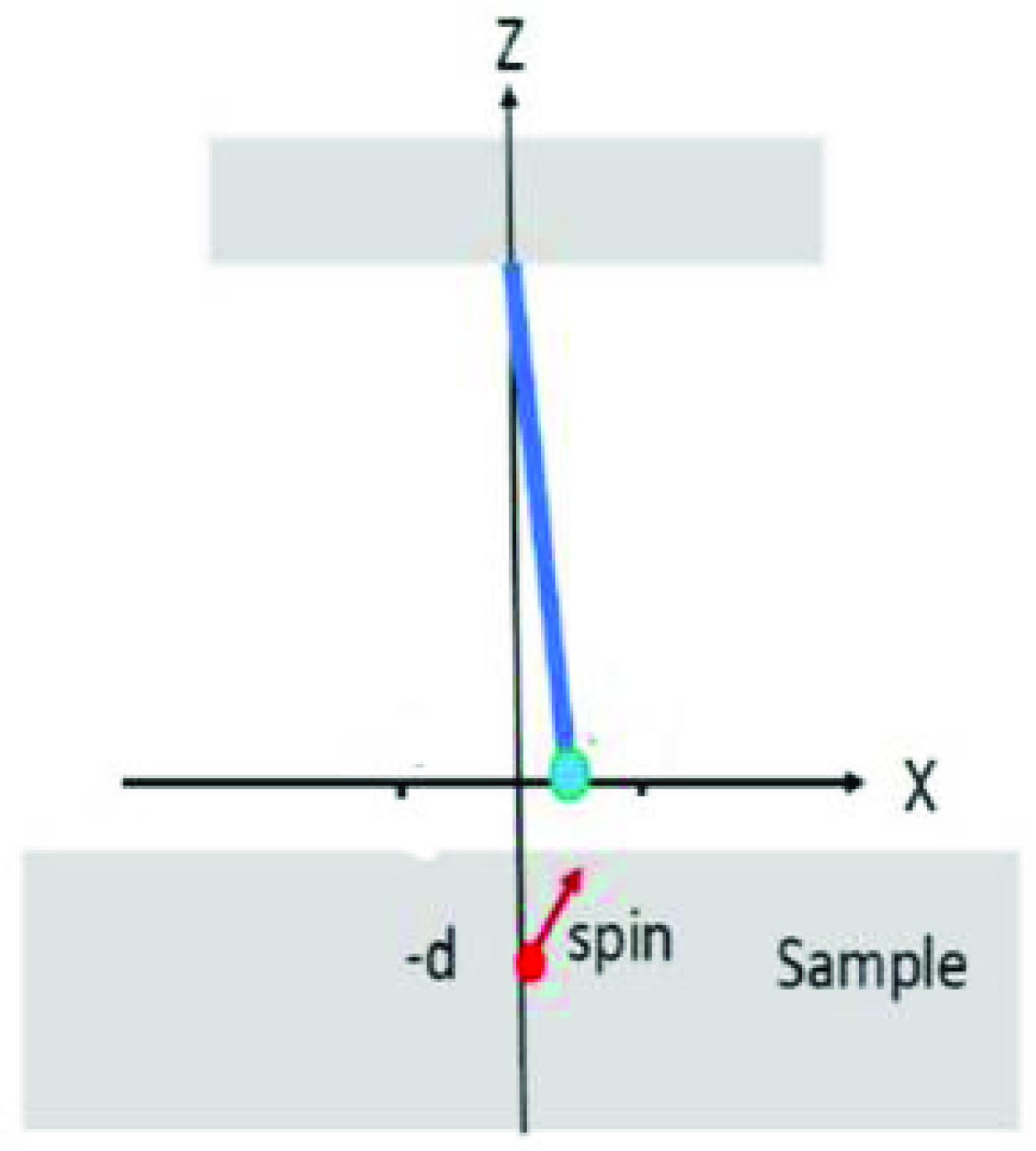
Figure 1. The oscillating cantilever with the ferromagnetic particle at its tip and a single electron spin in a sample.
Magnetochemistry 08 00076 g001
Publisher’s Note: MDPI stays neutral with regard to jurisdictional claims in published maps and institutional affiliations.