
Magnonic Crystal with Strips of Magnetic Nanoparticles: Modeling and Experimental Realization via a Dip-Coating Technique

 , ,
, ,  and
and 
Abstract
:1. Introduction
2. Transfer Matrix Approach
2.1. Propagation Matrix
2.2. Reflection Matrix
3. Experiment
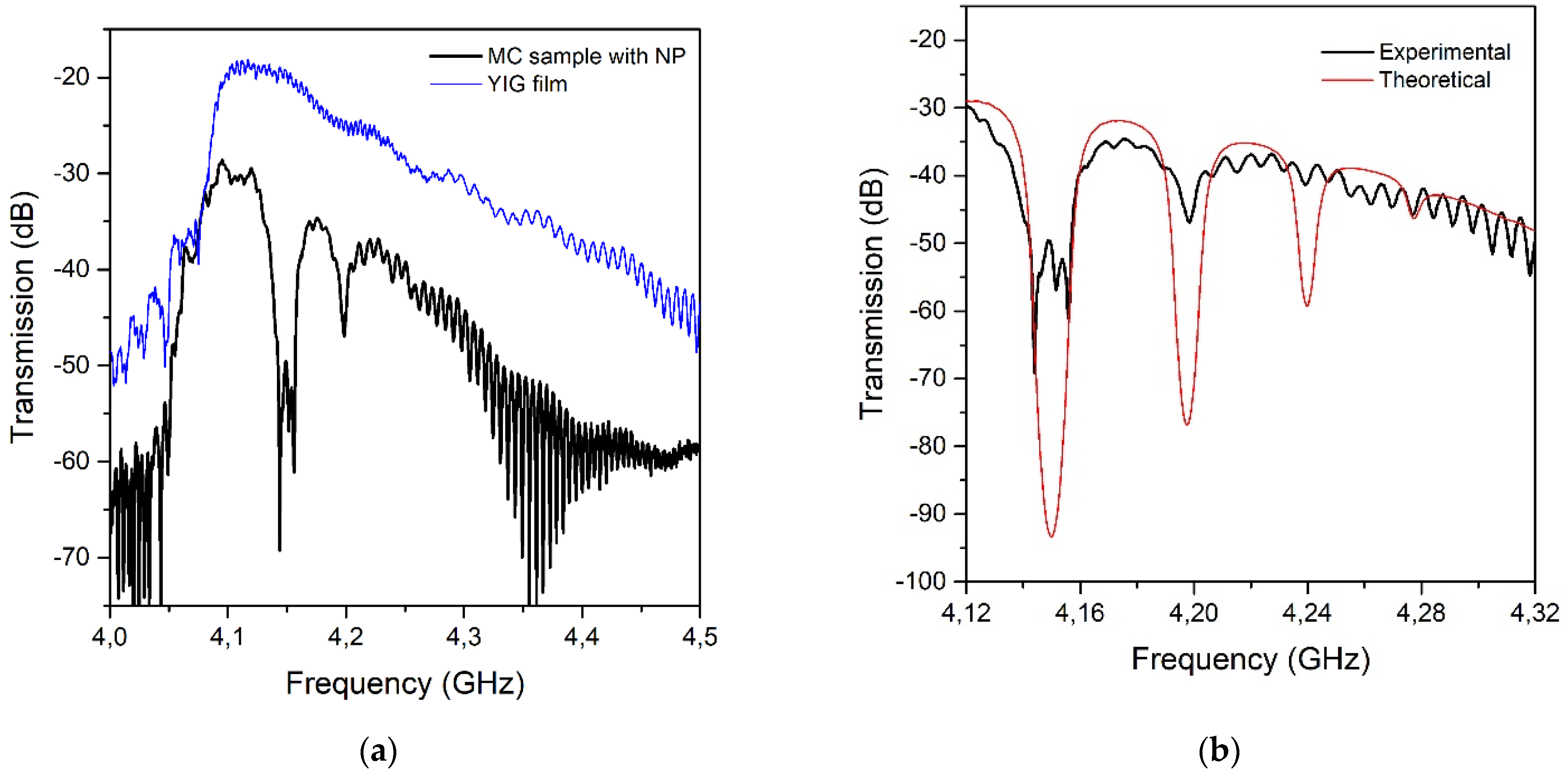
4. Discussion
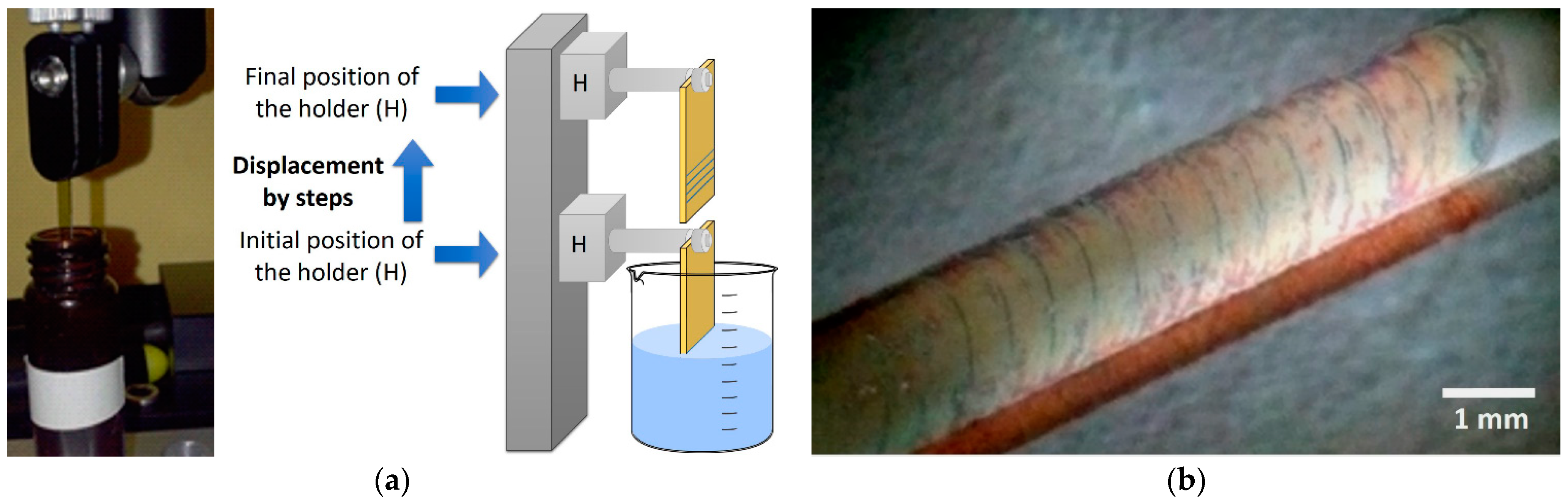
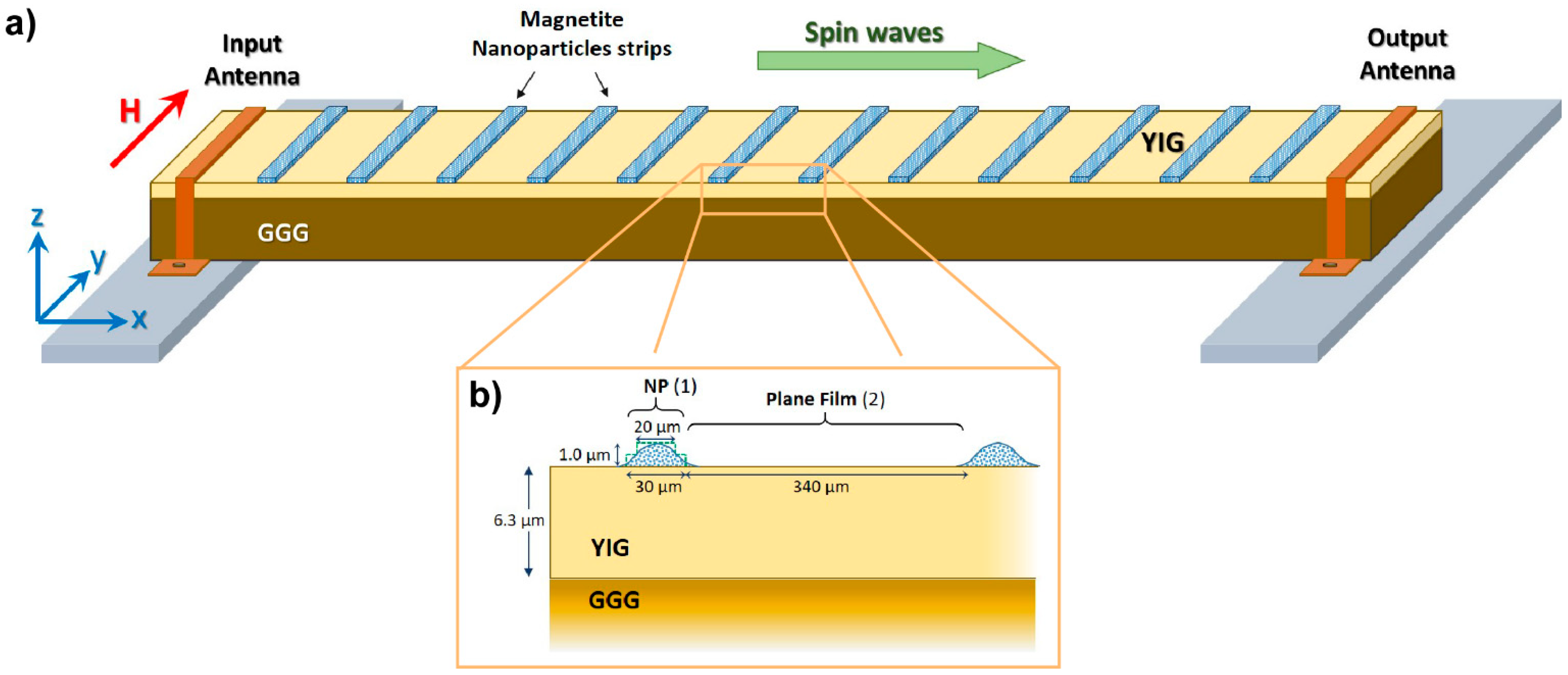
5. Materials and Methods
6. Conclusions
Author Contributions
Funding
Institutional Review Board Statement
Informed Consent Statement
Data Availability Statement
Acknowledgments
Conflicts of Interest
References
- Ustinov, A.B.; Grigor’Eva, N.Y.; Kalinikos, B. Observation of spin-wave envelope solitons in periodic magnetic film structures. JETP Lett. 2008, 88, 31–35. [Google Scholar] [CrossRef]
- Ustinov, A.B.; Kalinikos, B.A.; Demidov, V.E.; Demokritov, S.O. A spin-wave logic gate based on a width-modulated dynamic magnonic crystal. Appl. Phys. Lett. 2015, 106, 102405. [Google Scholar] [CrossRef] [Green Version]
- Drozdovskii, A.V.; Kalinikos, B. Observation of self-modulation spin-wave instability in a one-dimensional magnonic crystal. JETP Lett. 2012, 95, 357–361. [Google Scholar] [CrossRef]
- Ustinov, A.B.; Drozdovskii, A.V.; Kalinikos, B. Multifunctional nonlinear magnonic devices for microwave signal processing. Appl. Phys. Lett. 2010, 96, 142513. [Google Scholar] [CrossRef]
- Chumak, A.V.; Tiberkevich, V.S.; Karenowska, A.D.; Serga, A.A.; Gregg, J.F.; Slavin, A.N.; Hillebrands, B. All-linear time reversal by a dynamic artificial crystal. Nat. Commun. 2010, 1, 141. [Google Scholar] [CrossRef]
- Karenowska, A.D.; Chumak, A.; Serga, A.A.; Gregg, J.F.; Hillebrands, B. Magnonic crystal based forced dominant wavenumber selection in a spin-wave active ring. Appl. Phys. Lett. 2010, 96, 82505. [Google Scholar] [CrossRef] [Green Version]
- Gulyaev, Y.V.; Nikitov, A.A. Magnonic crystals and spin waves in periodic structures. Dokl. Phys. 2001, 46, 687–689. [Google Scholar] [CrossRef]
- Chumak, A.V.; Neumann, T.; Serga, A.A.; Hillebrands, B.; Kostylev, M.P. A current-controlled, dynamic magnonic crys-tal. J. Phys. D Appl. Phys. 2009, 42, 205005. [Google Scholar] [CrossRef]
- Chumak, A.V.; Pirro, P.; Serga, A.A.; Kostylev, M.P. Spin-wave propagation in a microstructured magnonic crystal. Appl. Phys. Lett. 2009, 95, 262508. [Google Scholar] [CrossRef] [Green Version]
- Chumak, A.; Serga, A.A.; Wolff, S.; Hillebrands, B.; Kostylev, M.P. Scattering of surface and volume spin waves in a magnonic crystal. Appl. Phys. Lett. 2009, 94, 172511. [Google Scholar] [CrossRef]
- Chumak, A.; Serga, A.A.; Wolff, S.; Hillebrands, B.; Kostylev, M.P. Design and optimization of one-dimensional ferrite-film based magnonic crystals. J. Appl. Phys. 2009, 105, 083906. [Google Scholar] [CrossRef] [Green Version]
- Ciubotaru, F.; Chumak, A.; Obry, B.; Serga, A.A.; Hillebrands, B. Magnonic band gaps in waveguides with a periodic variation of the saturation magnetization. Phys. Rev. B 2013, 88. [Google Scholar] [CrossRef] [Green Version]
- Chumak, A.V.; Serga, A.A.; Hillebrands, B. Magnon transistor for all-magnon data processing. Nat. Commun. 2014, 5, 4700. [Google Scholar] [CrossRef] [Green Version]
- Serga, A.A.; Chumak, A.V.; Hillebrands, B. YIG magnonics. J. Phys. D Appl. Phys. 2010, 43, 264002. [Google Scholar] [CrossRef]
- Vogel, M.; Chumak, A.V.; Waller, E.H.; Langner, T.; Vasyuchka, V.I.; Hillebrands, B.; von Freymann, G. Optically reconfig-urable magnetic materials. Nat. Phys. 2015, 11, 487–491. [Google Scholar] [CrossRef] [Green Version]
- Wang, Q.; Chumak, A.V.; Jin, L.; Zhang, H.; Hillebrands, B.; Zhong, Z. Voltage-controlled nanoscale reconfigurable mag-nonic crystal. Phys. Rev. B 2017, 95, 134433. [Google Scholar] [CrossRef] [Green Version]
- Wang, Z.K.; Zhang, V.L.; Lim, H.S.; Ng, S.C.; Kuok, M.H.; Jain, S.; Adeyeye, A.O. Observation of frequency band gaps in a one-dimensional nanostructured magnonic crystal. Appl. Phys. Lett. 2009, 94, 83112. [Google Scholar] [CrossRef] [Green Version]
- Obry, B.; Pirro, P.; Brächer, T.; Chumak, A.; Osten, J.; Ciubotaru, F.; Serga, A.A.; Fassbender, J.; Hillebrands, B. A micro-structured ion-implanted magnonic crystal. Appl. Phys. Lett. 2013, 102, 202403. [Google Scholar] [CrossRef]
- Sokolovskyy, M.L.; Klos, J.W.; Mamica, S.; Krawczyk, M. Calculation of the spin-wave spectra in planar magnonic crystals with metallic overlayers. J. Appl. Phys. 2012, 111, 07C515. [Google Scholar] [CrossRef]
- Nikitin, A.A.; Nikitin, A.A.; Ustinov, A.B.; Lahderanta, E.; Kalinikos, B. Theory of Spin-Electromagnetic Waves in Planar Thin-Film Multiferroic Heterostructures Based on a Coplanar Transmission Line and Its Application for Electromagnonic Crystals. IEEE Trans. Magn. 2018, 54, 2501805. [Google Scholar] [CrossRef]
- Ustinov, A.B.; Drozdovskii, A.V.; Nikitin, A.A.; Semenov, A.A.; Bozhko, D.; Serga, A.A.; Hillebrands, B.; Lähderanta, E.; Kalinikos, B. Dynamic electromagnonic crystal based on artificial multiferroic heterostructure. Commun. Phys. 2019, 2, 137. [Google Scholar] [CrossRef]
- Grigorieva, N.Y.; Kalinikos, B.A. Dispersion characteristics of spin waves in planar periodic structures based on ferro-magnetic flims. Tech. Phys. 2009, 54, 1196–1203. [Google Scholar] [CrossRef]
- Matatagui, D.; Kolokoltsev, O.V.; Qureshi, N.; Mejía-Uriarte, E.V.; Saniger, J.M. Magnonic gas sensor based on mangnetic na-noparticles. Nanoscale 2015, 7, 9607–9613. [Google Scholar] [CrossRef]
- Matatagui, D.; Kolokoltsev, O.; Qureshi, N.; Uriarte, E.V.M.; Ordoñez-Romero, C.; Vazquez-Olmos, A.; Saniger, J. Magnonic sensor array based on magnetic nanoparticles to detect, discriminate and classify toxic gases. Sens. Actuators B Chem. 2017, 240, 497–502. [Google Scholar] [CrossRef]
- Krawczyk, M.; Grundler, D. Review and prospects of magnonic crystals and devices with reprogrammable band struc-ture. J. Phys. Condens. Matter 2014, 26, 123202. [Google Scholar] [CrossRef] [PubMed]
- Sunaryono, S.; Taufiq, A.; Munaji1, M.; Indarto, B.; Triwikantoro, T.; Zainuri, M.; Darminto, D. Magneto-elasticity in hydrogels containing nanoparticles and their potential applications. AIP Conf. Proc. 2013, 1555, 53–56. [Google Scholar]
- Stancil, D.D.; Prabhakar, A. Spin Waves Theory and Applications; Springer: New York, NY, USA, 2009. [Google Scholar]
- Xu, H.; Wu, P.; Zhu, C.; Elbaz, A.; Gu, Z.Z. Photonic crystal for gas sensing. J. Mater. Chem. C 2013, 1, 6087–6098. [Google Scholar] [CrossRef]
- Ahmed, A.M.; Mehaney, A. Ultra-high sensitive 1D porous silicon photonic crystal sensor based on the coupling of Tamm/Fano resonances in the mid-infrared region. Sci. Rep. 2019, 9, 6973. [Google Scholar] [CrossRef] [Green Version]
- Ivanov, I.; Skryshevsky, V.; Belarouci, A. Porous Bragg reflector based sensors: Ways to increase sensitivity. Sens. Actuators A Phys. 2020, 315, 112234. [Google Scholar] [CrossRef]
- Lucklum, R.; Zubtsov, M.; Ke, M. Liquid sensor utilizing a regular phononic crystal with normal incidence of sound. IEEE Trans. Ultrason. Ferroelectr. Freq. Control 2012, 59, 463–471. [Google Scholar] [CrossRef]
- Shaban, S.M.; Mehaney, A.; Aly, A.H. Determination of 1-propanol, ethanol, and methanol concentrations in water based on a one-dimensional phoxonic crystal sensor. Appl. Opt. 2020, 59, 3878–3885. [Google Scholar] [CrossRef] [PubMed]
- Domínguez-Juárez, J.L.; Ordóñez-Romero, C.L.; Matatagui, D.; Kolokoltsev, O.; Quintero-Torres, R.; Aragón, J.L. Magnonic crystal via dip coating nanoparticles films. In Proceedings of the XXIV International Materials Research Congress, Oral Presentation, Cancun, Mexico, 16–20 August 2015. [Google Scholar]
- Wang, Y.; Zhang, M.; Lai, Y.; Chi, L. Advanced colloidal lithography: From patterning to applications. Nano Today 2018, 22, 36–61. [Google Scholar] [CrossRef]
- Chumak, A.V.; A Serga, A.; Hillebrands, B. Magnonic crystals for data processing. J. Phys. D Appl. Phys. 2017, 50, 244001. [Google Scholar] [CrossRef]
- Inoue, M.; Baryshev, A.; Takagi, H.; Lim, P.B.; Hatafuku, K.; Noda, J.; Togo, K. Investigating the use of magnonic crystals as extremely sensitive magnetic field sensors at room temperature. Appl. Phys. Lett. 2011, 98, 132511. [Google Scholar] [CrossRef]
- Lu, A.; Salabas, E.; Schüth, F. Magnetic Nanoparticles: Synthesis, Protection, Functionalization, and Application. Angew. Chem. Int. Ed. 2007, 46, 1222–1244. [Google Scholar] [CrossRef] [PubMed]
- Alexiou, C.; Schmid, R.J.; Jurgons, R.; Kremer, M.; Wanner, G.; Bergemann, C.; Huenges, E.; Nawroth, T.; Arnold, W.; Parak, F.G. Targeting cancer cells: Magnetic nanoparticles as drug carriers. Eur. Biophys. J. 2006, 35, 446–450. [Google Scholar] [CrossRef]
- Revia, R.A.; Zhang, M. Magnetite nanoparticles for cancer diagnosis, treatment, and treatment monitoring: Recent advances. Mater. Today 2016, 19, 157–168. [Google Scholar] [CrossRef]
- Haitian, X.; Steven, J.; Byoung-Chul, C.; Reuven, G. Characterization of Individual Magnetic Nanoparticles in Solution by Double Nanohole Optical Tweezers. Nano Lett. 2016, 16, 2639–2643. [Google Scholar]
- Dimitrov, A.S.; Nagayama, K. Continuous Convective Assembling of Fine Particles into Two-Dimensional Arrays on Solid Surfaces. Langmuir 1996, 12, 1303–1311. [Google Scholar] [CrossRef]

Publisher’s Note: MDPI stays neutral with regard to jurisdictional claims in published maps and institutional affiliations. |
© 2021 by the authors. Licensee MDPI, Basel, Switzerland. This article is an open access article distributed under the terms and conditions of the Creative Commons Attribution (CC BY) license (https://creativecommons.org/licenses/by/4.0/).
Share and Cite
Lazcano-Ortiz, Z.; Ordóñez-Romero, C.L.; Domínguez-Juárez, J.L.; Monsivais, G.; Quintero-Torres, R.; Matatagui, D.; Fragoso-Mora, J.R.; Qureshi, N.; Kolokoltsev, O. Magnonic Crystal with Strips of Magnetic Nanoparticles: Modeling and Experimental Realization via a Dip-Coating Technique. Magnetochemistry 2021, 7, 155. https://doi.org/10.3390/magnetochemistry7120155
Lazcano-Ortiz Z, Ordóñez-Romero CL, Domínguez-Juárez JL, Monsivais G, Quintero-Torres R, Matatagui D, Fragoso-Mora JR, Qureshi N, Kolokoltsev O. Magnonic Crystal with Strips of Magnetic Nanoparticles: Modeling and Experimental Realization via a Dip-Coating Technique. Magnetochemistry. 2021; 7(12):155. https://doi.org/10.3390/magnetochemistry7120155
Chicago/Turabian StyleLazcano-Ortiz, Zorayda, Cesar L. Ordóñez-Romero, Jorge Luis Domínguez-Juárez, Guillermo Monsivais, Rafael Quintero-Torres, Daniel Matatagui, José Roberto Fragoso-Mora, Naser Qureshi, and Oleg Kolokoltsev. 2021. "Magnonic Crystal with Strips of Magnetic Nanoparticles: Modeling and Experimental Realization via a Dip-Coating Technique" Magnetochemistry 7, no. 12: 155. https://doi.org/10.3390/magnetochemistry7120155
APA StyleLazcano-Ortiz, Z., Ordóñez-Romero, C. L., Domínguez-Juárez, J. L., Monsivais, G., Quintero-Torres, R., Matatagui, D., Fragoso-Mora, J. R., Qureshi, N., & Kolokoltsev, O. (2021). Magnonic Crystal with Strips of Magnetic Nanoparticles: Modeling and Experimental Realization via a Dip-Coating Technique. Magnetochemistry, 7(12), 155. https://doi.org/10.3390/magnetochemistry7120155