Abstract
The skyrmion racetrack is a promising concept for future information technology. The primary issues with skyrmion racetrack memory are now error codes and Hall motion. Here, we propose a skyrmion pair racetrack memory. The Oersted fields generated by the non-contact current-carrying wire in the middle of the magnetic nanostrip stabilize the skyrmion pairs in the nanostrip, which are separated by a naturally formed domain wall. Through numerical models and micromagnetic simulations, we demonstrate that such a skyrmion pair can produce linear Hall motion along the nanostrip under the linear control of the Oersted field gradient. These findings offer a high-reliability method for skyrmion racetrack memory and a more efficient approach to designing devices that use the skyrmion Hall effect.
1. Introduction
Magnetic skyrmions are a type of particle-like spin texture with a unique topological charge [1,2,3,4,5,6,7,8,9], which are considered to be ideal information storage units due to their small size, non-volatility, and low energy consumption [10,11,12,13,14]. In particular, in 2013, Fert et al. proposed a skyrmion-based racetrack memory, encoding binary information by the presence or absence of skyrmions in a nanostrip [10]. The theoretically driven current density of skyrmion-based racetrack memory is only [15,16], which is five orders of magnitude lower than the current density required for traditional magnetic domain wall (DW) racetrack memory [17,18]. This study illustrated the benefits of skyrmions in terms of low energy usage and also made skyrmion-based racetrack memory a research hotspot in the past 10 years.
However, there are certain significant architectural obstacles that current research must overcome before skyrmion-based racetrack memory can be used in practice. On the one hand, it is unreliable to move and read lengthy data bit sequences in nanostrips, particularly when process changes and temperature fluctuations caused by current are taken into account. An electric field-controlled dual-track skyrmion racetrack memory is one such approach [19]. In these devices, the bit value (0 or 1) is no longer determined by the presence of magnetic skyrmions in one track, but by the presence of skyrmions in two tracks [20,21]. On the other hand, when the skyrmions are moved by the spin-polarized current, the Magnus force acting on the moving skyrmion leads to the transverse motion of a magnetic skyrmion in the nanostrip, which is called the magnetic skyrmion Hall effect (SkHE) [22,23,24]. One alternative solution is to construct antiferromagnetic skyrmions [25,26,27,28,29,30,31,32,33,34], compensated ferrimagnetic skyrmions [13,35,36,37,38], or skyrmioniums [39,40,41] with zero topological charge. Recently, researchers otherwise implemented intrinsic skyrmion Hall motion for building racetrack-like devices.
Here, we propose a skyrmion pair racetrack memory device. In the center of the nanostrip, a non-contact neighboring wire is built. As a current is passed through the wire, Oersted fields of equal magnitude and opposite direction are generated on the nanostrip, together with a corresponding Oersted field gradient. Through micromagnetic simulations, we demonstrate that such Oersted fields can stabilize a pair of opposite polarized skyrmions separated by a DW in the nanostrip. The Oersted field gradients generate a Magnus force in the direction perpendicular to the gradient, leading to the Hall motion of the skyrmion pair along the nanostrip. Due to the effect of the DW at the center of the nanostrip, the stability and movement speed of the skyrmion pair in the racetrack are higher than those of a single skyrmion. Furthermore, this racetrack storage may successfully avoid the local temperature effect caused by the current because it does not require current to pass across the nanostrip, enhancing the device’s dependability and longevity.
2. Results and Discussions
Figure 1a shows the device structure, which consists of a magnetic nanostrip and a non-contacting wire above it. When current is passed through the middle wire, the generated Oersted fields can be calculated by the Biot-Savart law:
where is the applied current, is the integration path, and x is the transverse distance from the measuring position to the wire. Since the length of the sample is much smaller than the length of the conducting wire, we can approximate that the length of the conducting wire is infinite. This result is a simplification of . Considering a thin wire with a given width a, the generated Oersted field in the z-direction () can be expressed as follows:
where is the vacuum permeability. The corresponding Oersted field gradient can be determined by calculating the derivative of the Oersted field:
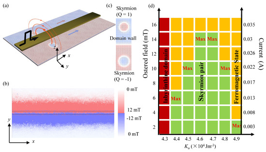
Figure 1.
The skyrmion pair racetrack device. (a) Device diagram. (b) The FEM calculation of the current-generated Oersted fields. (c) The magnetic moment distribution of the skyrmion–DW–skyrmion structure. (d) The phase diagram as a function of the Oersted field, and the corresponding current and PMA.
This equation indicates a monotonic decrease of as a function of distance (.
For nm, A, we use the finite element method (FEM) in COMSOL Multi-physics software 6.1 to calculate the distribution of the generated Oersted fields on the nanostrip. The calculation results are shown in Figure 1b. The depth of red (blue) represents the magnitude of the Oersted field on the nanostrip. The intensity of the Oersted field gradually decays with the increase in distance , consistent with the prediction of the Biot–Savart law.
The Oersted field gradient has been shown to effectively manipulate the movement of skyrmions [42,43,44,45]. All micromagnetic simulations were performed using Mumax 3.10 [46], based on the Landau-Lifshitz-Gilbert (LLG) equation, expressed as follows [47]:
where is the gyromagnetic ratio, is the damping coefficient, is the normalized magnetic vector, is the time derivative of . is the effective field where the total energy in our studied system is . We consider the Neumann boundary conditions and the interfacial Dzyaloshinskii-Moriya interaction (i-DMI) energy as follows:
where is the i-DMI strength. The exchange energy is given by the following:
where is the exchange constant. The demagnetization energy is as follows:
where is the demagnetization field, is the vacuum permeability, and is the saturation magnetization. The uniaxial anisotropy energy is as follows:
where is perpendicular magnetization anisotropy. The effect of Oersted fields is given by a Zeeman energy as follows:
where is the Oersted field. We study the case where the skyrmion pair moves under a spatially inhomogeneous magnetic field of the form , with a gradient along the x-direction ().
Through micromagnetic simulations, Mumax3, we initialize two skyrmions with opposite topological charges on the left and right sides of the nanostrip, as shown in Figure 1a. In the micromagnetic simulation, the magnetic parameters are based on a known chiral magnet system, specifically the Ta/CoFeB/MgO material parameter system in reference [47], which exhibits finite DMI that can stabilize skyrmions: In the micromagnetic simulation, the mesh size in the simulation is , the diameter of the nanostrip is , the vertical magnetization anisotropy is , the saturation magnetization is , the exchange constant is , the damping coefficient is , and the interfacial Dzyaloshinskii-Moriya interaction (iDMI) intensity is . In the simulation, a periodic boundary condition was applied only along the x direction of the nanostrip. The Oersted fields obtained by the FEM are introduced into the simulations through external magnetic fields, and their magnetic field gradient is approximated as a uniform value.
Under the combined action of the Oersted fields and the DMI, a chiral DW is formed under the wire, forming a skyrmion–DW–skyrmion magnetic moment structure in the nanostrip, as shown in Figure 1c. To investigate the correlation between the current and the skyrmion–DW–skyrmion structure, the phase diagram as a function of the Oersted field, the corresponding current, and PMA is presented in Figure 1d. When the Oersted field exceeds the maximum tolerable threshold, it will provide sufficient driving force for skyrmions to surmount the energy barrier, thereby inducing their gradual annihilation and a subsequent phase transition to the ferromagnetic (FM) state. Notably, as the PMA increases, the magnetic system exhibits an enhanced tendency to transition to the FM state. Consequently, the maximum Oersted field that the system can tolerate decreases accordingly.
Assuming that the skyrmion is a rigid particle, the dynamics of skyrmions under an Oersted field gradient can be studied by using the Thiele equation [48]:
where is the gyromagnetic coupling vector, is the gyromagnetic ratio, is the skyrmion drift velocity, and is the dissipation tensor. Here, the force induced by the Oersted field gradient is given by , where is the Zeeman energy, is the magnetic vector, and is the Oersted field. It can be written as follows:
By assuming that the magnetic moment of the ferromagnetic background is opposite to the topological charge, we can simplify Equation (11) to the following:
where we have applied a partial integration [41,49,50] and converted the integration interval to the area of skyrmion S, and the following:
For a unit skyrmion, . Under DW and boundary constraints, the motion of skyrmions in the y direction is restricted (). Here, we can simplify Equation (10) to the following:
Therefore, the skyrmion velocity can be given by the following:
It can be predicted from the Thiele equation that (1) the velocity of the skyrmions is along the x direction, (2) the velocity of the skyrmions is independent of , and (3) the velocity of the skyrmions is proportional to . Since the Oersted field gradient generated by the current-carrying wire on both sides has the same direction and symmetric magnitude, the skyrmions on both sides will move with the same velocity.
We performed micromagnetic simulations on the movement of the skyrmion pair in a nanostrip. The skyrmion-pair movement trajectories (marked by a blue-dotted box) are shown in Figure 2a. As expected, throughout its motion, the skyrmion pair does not cause any displacement in the y direction. Figure 2b illustrates how the displacement in the x direction varies with time . The displacement of the skyrmion pair changes linearly with time, indicating a uniform speed. From the slope, we can read that the velocity of the skyrmion pair is 1.2 m/s.
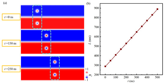
Figure 2.
Movement of the skyrmion pair in the racetrack device. (a) The skyrmion pair movement trajectories. (b) The displacement of the skyrmion pair in the x direction changes as a function of time .
In the movement of the skyrmion pair, the DW between the two skyrmions is responsible for restricting the y-directional deviation of the skyrmion pair. In order to analyze the effect of the DW on the movement of the skyrmion pair, we further compared the movement of the skyrmion pair and the single skyrmion under the Oersted field gradient. Under the action of the initial Oersted field of 10 mT and the gradient of 0.234 nm/mT, the trajectories of the skyrmion pair and the single skyrmion in 600 ns are shown in Figure 3a. Obviously, the movement speed of the skyrmion pair is much faster than that of the single skyrmion. Due to the presence of the skyrmion–DW–skyrmion coupling structure, a “push-pull” effect emerges between the intermediate DW and the skyrmions on both sides under the influence of the Oersted field gradient. Specifically, the repulsive forces between the intermediate DW and these skyrmions serve to enhance the y-direction driving force acting on them, resulting in a stronger SkHE and thus further leading to a higher motion velocity in the x direction.
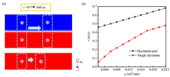
Figure 3.
Comparison between the movement of the skyrmion pair and the single skyrmion under the Oersted field gradient. (a) Movement trajectories. (b) The velocity of the skyrmion pair and the single skyrmion as a function of the Oersted field gradient.
In contrast, in the case of a single skyrmion, the current wire is fabricated on the right side of the entire nanostrip (its structure is shown in Supplementary Figure S2). Figure 3b displays the velocity of the single skyrmion and the skyrmion pair as a function of the Oersted field gradient. Since the skyrmion pair is influenced in the y direction under the action of the DW, its movement speed in the x direction is linearly regulated by , which is also in line with the calculation conclusion of the Thiele equation (Equation (15)). Due to the absence of repulsive force between the skyrmion and the DW, the speed of the single skyrmion is slower than that of the skyrmion pair, and the Hall angle of the single skyrmion is slightly smaller than that of the skyrmion with the same topological charge in the skyrmion pair. The Hall angle comparison between the skyrmion pair () and the single skyrmion is shown in Supplementary Figure S5.
In addition to the limitation of the DW, the boundary effect of the nanostrip also contributes to the relocation of skyrmions in the y direction. As illustrated in Figure 4, we determined the skyrmion pair velocity as a function of the nanostrip width under three Oersted field gradient magnitudes. This is because the boundary effect of the nanostrip decreases with the increase in width. At this time, the skyrmion will have a velocity component in the y direction, following a decrease in the velocity component in the x direction. However, the skyrmions only have the Hall motion induced by SkHE along the x direction due to the boundary effect. Furthermore, when the track length reaches 5 μm, snapshots of the skyrmion motion process (Supplementary Figure S1) show the the skyrmion Hall motion induced by the transverse Oersted field can be fully utilized for directional transport along the x direction, without reaching the width edge of the track and being pinned.
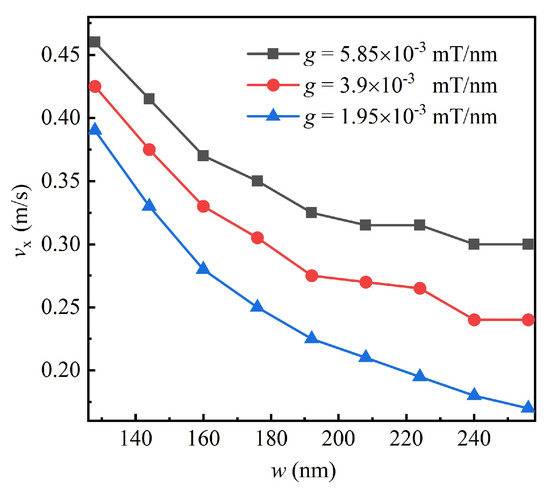
Figure 4.
The skyrmion pair velocity as a function of the nanostrip width under three Oersted field gradient magnitudes.
3. Conclusions
In this work, we propose a skyrmion pair racetrack memory. Through the Oersted fields generated by an on-chip non-contact current-carrying wire above the magnetic nanostrip, a pair of skyrmions with opposite topological charges can be stabilized on two sides of the wire, forming a skyrmion–DW–skyrmion spin structure. Through FEM, the Thiele equation, and micromagnetic simulations, we demonstrate that in this racetrack memory, the skyrmion pair can be linearly manipulated to move along the strip in a straight line through the Oersted field gradient. This method offers a dependable design concept for the skyrmion racetrack memory and could also be used for magnetic insulator materials.
Supplementary Materials
The following supporting information can be downloaded at https://www.mdpi.com/article/10.3390/magnetochemistry11100090/s1; Figure S1: the motion of skyrmion pair in the ultra-long track (5 μm); Figure S2: The device diagram of the single skyrmion racetrack device; Figure S3: The skyrmion pair velocity comparison between the methods of PMA gradient and Oersted field gradient; Figure S4: the motion of skyrmion pair under different mesh size in the simulation; Figure S5: The Hall angle comparison of the skyrmion pair (Q = 1 and Q = −1) and the single skyrmion under different nanostrip width.
Author Contributions
Conceptualization, S.Q. and J.L.; methodology, X.H.; software, S.Q. and T.Z.; validation, T.Z.; writing—original draft preparation, S.Q.; writing—review and editing, S.Q., Y.C. and L.F.; visualization, J.L.; funding acquisition, L.F. and Y.C. All authors have read and agreed to the published version of the manuscript.
Funding
This work was supported by the National Natural Science Foundation of China (Grant Nos. 12304160, 62172155, 62274183, and 62301595), the Research Foundation from NUDT (Grant Nos. ZK24-18, 23-ZZCX-ZZGC-01-02, and 22-ZZCX-046-02), the Natural Science Foundation of Hunan Province (Grant Nos. 2024JJ7250, 2022JJ40563), the Hunan Provincial Education Department Foundation Key Project (21A0557) and the National Key R & D Program of China (Grant No. 2023YFB4502100).
Institutional Review Board Statement
Not applicable.
Informed Consent Statement
Not applicable.
Data Availability Statement
The original contributions presented in this study are included in the article/Supplementary Material. Further inquiries can be directed to the corresponding author.
Conflicts of Interest
The authors declare no conflicts of interest.
References
- Yu, X.Z.; Onose, Y.; Kanazawa, N.; Park, J.H.; Han, J.H.; Matsui, Y. Real-space observation of a two-dimensional skyrmion crystal. Nature 2010, 465, 901–904. [Google Scholar] [CrossRef]
- Heinze, S.; von Bergmann, K.; Menzel, M.; Brede, J.; Kubetzka, A.; Wiesendanger, R. Spontaneous atomic-scale magnetic skyrmion lattice in two dimensions. Nat. Phys. 2011, 7, 713–718. [Google Scholar] [CrossRef]
- Tonomura, A.; Yu, X.Z.; Yanagisawa, K.; Matsuda, T.; Onose, Y.; Kanazawa, N. Real-Space Observation of Skyrmion Lattice in Helimagnet MnSi Thin Samples. Nano Lett. 2012, 12, 1673–1677. [Google Scholar] [CrossRef] [PubMed]
- Jiang, W.J.; Chen, G.; Liu, K.; Zang, J.D.; te Velthuis, S.G.E.; Hoffmann, A. Skyrmions in magnetic multilayers. Phys. Rep. Rev. Sect. Phys. Lett. 2017, 704, 1–49. [Google Scholar] [CrossRef]
- Deng, Z.; Shi, T.; Krasnok, A.; Li, X.P.; Alù, A. Observation of localized magnetic plasmon skyrmions. Nat. Commun. 2022, 13, 1. [Google Scholar] [CrossRef] [PubMed]
- Wang, W.W.; Song, D.S.; Wei, W.S.; Nan, P.F.; Zhang, S.L.; Ge, B.H. Electrical manipulation of skyrmions in a chiral magnet. Nat. Commun. 2022, 13, 1593. [Google Scholar] [CrossRef] [PubMed]
- Fert, A.; Reyren, N.; Cros, V. Magnetic skyrmions: Advances in physics and potential applications. Nat. Rev. Mater. 2017, 2, 7. [Google Scholar] [CrossRef]
- Ullah, A.; Balasubramanian, B.; Tiwari, B.; Giri, B.; Sellmyer, D.J.; Skomski, R.; Xu, X.S. Topological spin textures and topological Hall effect in centrosymmetric magnetic nanoparticles. Phys. Rev. B 2023, 108, 184432. [Google Scholar] [CrossRef]
- Ullah, A.; Balamurugan, B.; Zhang, W.; Valloppilly, S.; Li, X.Z.; Pahari, R.; Yue, L.P.; Sokolov, A.; Sellmyer, D.J.; Skomski, R. Crystal Structure and Dzyaloshinski-Moriya Micromagnetics. IEEE Trans. Magn. 2019, 55, 7100305. [Google Scholar] [CrossRef]
- Fert, A.; Cros, V.; Sampaio, J. Skyrmions on the track. Nat. Nanotechnol. 2013, 8, 152–156. [Google Scholar] [CrossRef]
- Zhang, X.C.; Ezawa, M.; Zhou, Y. Magnetic skyrmion logic gates: Conversion, duplication and merging of skyrmions. Sci. Rep. 2015, 5, 9400. [Google Scholar] [CrossRef]
- Song, K.M.; Jeong, J.S.; Pan, B.; Zhang, X.C.; Xia, J.; Cha, S. Skyrmion-based artificial synapses for neuromorphic computing. Nat. Electron. 2020, 3, 148–155. [Google Scholar] [CrossRef]
- Zhang, X.C.; Zhou, Y.; Song, K.M.; Park, T.E.; Xia, J.; Ezawa, M. Skyrmion-electronics: Writing, deleting, reading and processing magnetic skyrmions toward spintronic applications. J. Phys. Condens. Matter 2020, 32, 14. [Google Scholar] [CrossRef]
- Mishra, K.K.; Lone, A.H.; Srinivasan, S.; Fariborzi, H.; Setti, G. Magnetic skyrmion: From fundamental physics to pioneering applications. Appl. Phys. Rev. 2025, 12, 011315. [Google Scholar] [CrossRef]
- Yu, X.Z.; Kanazawa, N.; Onose, Y.; Kimoto, K.; Zhang, W.Z.; Ishiwata, S. Near room-temperature formation of a skyrmion crystal in thin-films of the helimagnet FeGe. Nat. Mater. 2011, 10, 106–109. [Google Scholar] [CrossRef] [PubMed]
- Jonietz, F.; Mühlbauer, S.; Pfleiderer, C.; Neubauer, A.; Münzer, W.; Bauer, A. Spin Transfer Torques in MnSi at Ultralow Current Densities. Science 2010, 330, 1648–1651. [Google Scholar] [CrossRef] [PubMed]
- Lepadatu, S.; Saarikoski, H.; Beacham, R.; Benitez, M.J.; Moores, T.A.; Burnell, G. Synthetic ferrimagnet nanowires with very low critical current density for coupled domain wall motion. Sci. Rep. 2017, 7, 1640. [Google Scholar] [CrossRef] [PubMed]
- Koyama, T.; Chiba, D.; Ueda, K.; Kondou, K.; Tanigawa, H.; Fukami, S. Observation of the intrinsic pinning of a magnetic domain wall in a ferromagnetic nanowire. Nat. Mater. 2011, 10, 194–197. [Google Scholar] [CrossRef]
- Lai, P.; Zhao, G.P.; Morvan, F.J.; Wu, S.Q.; Ran, N. Motion of Skyrmions in Well-Separated Two-Lane Racetracks. Spin 2017, 7, 1. [Google Scholar] [CrossRef]
- Song, C.K.; Jin, C.D.; Wang, J.S.; Xia, H.Y.; Wang, J.B.; Liu, Q.F. Skyrmion-based multi-channel racetrack. Appl. Phys. Lett. 2017, 111, 192413. [Google Scholar] [CrossRef]
- Göbel, B.; Mertig, I. Skyrmion ratchet propagation: Utilizing the skyrmion Hall effect in AC racetrack storage devices. Sci. Rep. 2021, 11, 3020. [Google Scholar] [CrossRef]
- Jiang, W.J.; Zhang, X.C.; Yu, G.Q.; Zhang, W.; Wang, X.; Jungfleisch, M.B. Direct observation of the skyrmion Hall effect. Nat. Phys. 2017, 13, 162–169. [Google Scholar] [CrossRef]
- Han, S.U.; Kim, W.; Kim, S.K.; Je, S.G. Tunable domain-wall skyrmion Hall effect driven by a current and a magnetic field. Phys. Rev. B 2024, 109, 014404. [Google Scholar] [CrossRef]
- Zeissler, K.; Finizio, S.; Barton, C.; Huxtable, A.J.; Massey, J.; Raabe, J. Diameter-independent skyrmion Hall angle observed in chiral magnetic multilayers. Nat. Commun. 2020, 11, 428. [Google Scholar] [CrossRef]
- Zhang, X.C.; Zhou, Y.; Ezawa, M. Antiferromagnetic Skyrmion: Stability, Creation and Manipulation. Sci. Rep. 2016, 6, 24795. [Google Scholar] [CrossRef] [PubMed]
- Barker, J.; Tretiakov, O.A. Static and Dynamical Properties of Antiferromagnetic Skyrmions in the Presence of Applied Current and Temperature. Phys. Rev. Lett. 2016, 116, 147203. [Google Scholar] [CrossRef] [PubMed]
- Jin, C.D.; Song, C.K.; Wang, J.B.; Liu, Q.F. Dynamics of antiferromagnetic skyrmion driven by the spin Hall effect. Appl. Phys. Lett. 2016, 109, 182404. [Google Scholar] [CrossRef]
- Pham, V.; Sisodia, N.; Di Manici, I.; Urrestarazu-Larrañaga, J.; Bairagi, K.; Pelloux-Prayer, J.; Guedas, R.; Buda-Prejbeanu, L.D.; Auffret, S.; Locatelli, A.; et al. Fast current-induced skyrmion motion in synthetic antiferromagnets. Science 2024, 384, 307–312. [Google Scholar] [CrossRef]
- Dohi, T.; DuttaGupta, S.; Fukami, S.; Ohno, H. Formation and current-induced motion of synthetic antiferromagnetic skyrmion bubbles. Nat. Commun. 2019, 10, 5153. [Google Scholar] [CrossRef]
- Legrand, W.; Maccariello, D.; Ajejas, F.; Collin, S.; Vecchiola, A.; Bouzehouane, K.; Reyren, N.; Cros, V.; Fert, A. Room-temperature stabilization of antiferromagnetic skyrmions in synthetic antiferromagnets. Nat. Mater. 2020, 19, 34–42. [Google Scholar] [CrossRef]
- Qiu, S.; Liu, J.H.; Chen, Y.B.; Qi, X.L.; Fang, L. Writing skyrmion at a specific position in synthetic antiferromagnetic racetrack by voltage. J. Magn. Magn. Mater. 2022, 554, 169144. [Google Scholar] [CrossRef]
- Gao, S.; Rosales, H.D.; Albarracín, F.G.A.; Tsurkan, V.; Kaur, G.; Fennell, T. Fractional antiferromagnetic skyrmion lattice induced by anisotropic couplings. Nature 2020, 586, 7827. [Google Scholar] [CrossRef]
- Göbel, B.; Mook, A.; Henk, J.; Mertig, I. Antiferromagnetic skyrmion crystals: Generation, topological Hall, and topological spin Hall effect. Phys. Rev. B 2017, 96, 060406. [Google Scholar] [CrossRef]
- Lau, M.; Häusler, W.; Thorwart, M. Moving skyrmions in antiferromagnets by sublattice displacements. Phys. Rev. B 2025, 111, 144411. [Google Scholar] [CrossRef]
- Kim, S.K.; Lee, K.J.; Tserkovnyak, Y. Self-focusing skyrmion racetracks in ferrimagnets. Phys. Rev. B 2017, 95, 140404. [Google Scholar] [CrossRef]
- Hirata, Y.; Kim, D.H.; Kim, S.K.; Lee, D.K.; Oh, S.H.; Kim, D.Y.; Nishimura, T.; Okuno, T.; Futakawa, Y.; Yoshikawa, H.; et al. Vanishing skyrmion Hall effect at the angular momentum compensation temperature of a ferrimagnet. Nat. Nanotechnol. 2019, 14, 232–236. [Google Scholar] [CrossRef]
- Xu, H.; Yang, Q.Q.; Liu, Y.; Tian, G.; Qiu, L.; Qin, M.H.; Hou, Z.P. Skyrmion Motion in Ferrimagnets Driven by Magnetic Anisotropy Gradient. Phys. Status Solidi-Rapid Res. Lett. 2024, 18, 5. [Google Scholar] [CrossRef]
- Vélez, S.; Ruiz-Gómez, S.; Schaab, J.; Gradauskaite, E.; Wörnle, M.S.; Welter, P.; Jacot, B.J.; Degen, C.L.; Trassin, M.; Fiebig, M.; et al. Current-driven dynamics and ratchet effect of skyrmion bubbles in a ferrimagnetic insulator. Nat. Nanotechnol. 2022, 17, 834–841. [Google Scholar] [CrossRef]
- Kolesnikov, A.G.; Stebliy, M.E.; Samardak, A.S.; Ognev, A.V. Skyrmionium—High velocity without the skyrmion Hall effect. Sci. Rep. 2018, 8, 1. [Google Scholar] [CrossRef]
- Yang, S.; Zhao, Y.L.; Wu, K.; Chu, Z.Q.; Xu, X.H.; Li, X.G. Reversible conversion between skyrmions and skyrmioniums. Nat. Commun. 2023, 14, 3405. [Google Scholar] [CrossRef] [PubMed]
- Zhang, S.L.; Kronast, F.; van der Laan, G.; Hesjedal, T. Real-Space Observation of Skyrmionium in a Ferromagnet-Magnetic Topological Insulator Heterostructure. Nano Lett. 2018, 18, 1057–1063. [Google Scholar] [CrossRef]
- Wang, C.J.; Xiao, D.; Chen, X.; Zhou, Y.; Liu, Y.W. Manipulating and trapping skyrmions by magnetic field gradients. New J. Phys. 2017, 19, 083008. [Google Scholar] [CrossRef]
- Cho, J.; Tamura, E.; Liu, C.Z.; Miki, S.; You, C.Y.; Kim, J.S. Manipulating 1-dimensional skyrmion motion by the external magnetic field gradient. New J. Phys. 2020, 22, 103053. [Google Scholar] [CrossRef]
- Zhou, S.; Wang, C.J.; Zheng, C.X.; Liu, Y.W. Manipulating skyrmions in synthetic antiferromagnetic nanowires by magnetic field gradients. J. Magn. Magn. Mater. 2020, 493, 165740. [Google Scholar] [CrossRef]
- Brearton, R.; Turnbull, L.A.; Verezhak, J.A.T.; Balakrishnan, G.; Hatton, P.D.; van der Laan, G.; Hesjedal, T. Deriving the skyrmion Hall angle from skyrmion lattice dynamics. Nat. Commun. 2021, 12, 2723. [Google Scholar]
- Vansteenkiste, A.; Leliaert, J.; Dvornik, M.; Helsen, M.; Garcia-Sanchez, F.; Van Waeyenberge, B. The design and verification of MuMax3. AIP Adv. 2014, 4, 10. [Google Scholar] [CrossRef]
- Liu, J.; Song, C.; Zhao, L.; Cai, L.; Feng, H.; Zhao, B.; Zhao, M.; Zhou, Y.; Fang, L.; Jiang, W. Manipulation of skyrmion by magnetic field gradients: A Stern–Gerlach-like experiment. Nano Lett. 2023, 23, 4931–4937. [Google Scholar] [CrossRef]
- Thiele, A.A. Steady-State Motion of Magnetic Domains. Phys. Rev. Lett. 1973, 30, 230–233. [Google Scholar] [CrossRef]
- Zhang, S.L.; Wang, W.W.; Burn, D.M.; Peng, H.; Berger, H.; Bauer, A. Manipulation of skyrmion motion by magnetic field gradients. Nat. Commun. 2018, 9, 2115. [Google Scholar] [CrossRef] [PubMed]
- Liang, J.J.; Yu, J.H.; Chen, J.; Qin, M.H.; Zeng, M.; Lu, X.B. Magnetic field gradient driven dynamics of isolated skyrmions and antiskyrmions in frustrated magnets. New J. Phys. 2018, 20, 053037. [Google Scholar] [CrossRef]


Disclaimer/Publisher’s Note: The statements, opinions and data contained in all publications are solely those of the individual author(s) and contributor(s) and not of MDPI and/or the editor(s). MDPI and/or the editor(s) disclaim responsibility for any injury to people or property resulting from any ideas, methods, instructions or products referred to in the content. |
© 2025 by the authors. Licensee MDPI, Basel, Switzerland. This article is an open access article distributed under the terms and conditions of the Creative Commons Attribution (CC BY) license (https://creativecommons.org/licenses/by/4.0/).