Article

Fragmentation Susceptibility of Controlled-Release Fertilizer Particles: Implications for Nutrient Retention and Sustainable Horticulture

1
College of Mechanical and Electronic Engineering, Shandong Agricultural University, Taian 271018, China
2
Shandong Key Laboratory of Intelligent Production Technology and Equipment for Facility Horticulture, Taian 271018, China
3
Shandong Engineering Research Center of Agricultural Equipment Intelligentization, Taian 271018, China
*
Authors to whom correspondence should be addressed.
Horticulturae 2025, 11(10), 1215; https://doi.org/10.3390/horticulturae11101215
Submission received: 14 September 2025 / Revised: 6 October 2025 / Accepted: 7 October 2025 / Published: 9 October 2025
(This article belongs to the Section Plant Nutrition)

Abstract

As an important technology to enhance nutrient use efficiency and reduce agricultural non-point source pollution, controlled-release fertilizers (CRFs) have been widely applied in modern agriculture. However, during packaging, transportation, and field application, CRF particles are prone to mechanical impacts, which can lead to particle fragmentation and damage to the controlled-release coating. This compromises the release kinetics, increases nutrient loss risk, and ultimately exacerbates environmental issues such as eutrophication. Currently, studies on the impact-induced fragmentation behavior of CRF particles remain limited, and there is an urgent need to investigate their fragmentation susceptibility mechanisms from the perspective of internal stress evolution. In this study, the mechanical properties of CRF particles were first experimentally determined to obtain essential parameters. A two-layer finite element model representing the coating and core structure of the particles was then constructed, and a fragmentation susceptibility index was proposed as the key evaluation criterion. The index, defined as the ratio of fractured volume to peak impact energy, reflects the efficiency of energy conversion at the critical moment of particle rupture (1–5). An explicit dynamic simulation framework incorporating multiple influencing factors—equivalent diameter, sphericity, impact material, velocity, and angle—was developed to analyze fragmentation behavior from the perspective of energy transformation. Based on the observed effects of these variables on fragmentation susceptibility, three regression models were developed using response surface methodology to quantitatively predict fragmentation susceptibility. Comparative analysis between the simulation and experimental results showed a fragmentation rate error range of 0–11.47%. The findings reveal the relationships between particle fragmentation modes and energy responses under various impact conditions. This research provides theoretical insights and technical guidance for optimizing the mechanical stability of CRFs and developing environmentally friendly fertilization strategies.

1. Introduction

The widespread application of controlled-release fertilizers (CRFs) has significantly improved nutrient use efficiency and effectively reduced environmental pollution compared with conventional fertilizers [1,2,3,4]. CRFs regulate nutrient release rates to match crop demands, thereby minimizing nutrient losses and environmental contamination caused by leaching, volatilization, and surface runoff [5,6,7]. However, CRF particles are often subjected to mechanical impacts during packaging, transportation, mechanical spreading, and soil incorporation, resulting in physical breakage. This breakage alters the surface area and structural integrity of the particles, accelerates nutrient release rates, and disrupts the intended release cycle [8,9,10]. Consequently, it may cause localized nutrient surges and shortened release durations, ultimately increasing nutrient leaching and elevating the risk of eutrophication in surrounding ecosystems [11,12,13,14,15]. The physical degradation of controlled-release fertilizer granules is driven by a combination of internal and external factors. Short-duration, high-energy events (such as bagging, bumpy transportation, mechanical spreading, and collision with the fertilizer discharge port) can induce stress concentrations on the granule surface, generating stress waves that trigger crack initiation and propagation, leading to localized coating rupture or fragmentation. Furthermore, the coating itself can suffer fatigue failure or rupture under repeated mechanical loading. Under conditions of moist heat, UV irradiation, or soil microbial activity, the polymer coating undergoes hydrolysis, swelling, or degradation, reducing its mechanical integrity and making it more susceptible to fragmentation during subsequent mechanical impact. Broken coating or granule fragments increase the effective surface area and disrupt the controlled-release structure, accelerating nutrient release [16,17,18] (2–5).
Although the structural integrity of particles plays a decisive role in the effectiveness of CRFs, quantitative investigations into particle breakage characteristics under dynamic impact conditions remain limited [19,20,21]. Existing research has primarily focused on the use of the Discrete Element Method (DEM) to study particle breakage under compression, or on quasi-static compression tests to assess mechanical properties [22,23,24,25]. These approaches fall short of realistically and effectively capturing the high-speed, high-energy collisions and internal stress developments experienced by CRFs in practical scenarios [26,27,28]. In recent years, the explicit dynamics module of the Finite Element Method (FEM) has been widely applied in modeling the impact responses of brittle or composite materials such as agricultural products, pharmaceutical tablets, and concrete [29,30,31,32]. These studies have elucidated critical processes such as stress wave propagation, crack initiation, and breakage mechanisms. For instance, Celik [33] used FEM to simulate mechanical damage in apples during postharvest handling, providing theoretical insights into the types and distributions of damage under specific harvesting conditions. Hou [34] developed a multi-scale FEM model of blueberries based on anatomical structures, incorporating both flesh and seeds. By coupling explicit dynamics simulations with response surface analysis, a predictive model for blueberry damage susceptibility was constructed to support mechanical harvesting and postharvest quality preservation. Yang [35] simulated the rupture behavior of pharmaceutical tablet coatings under internal expansion pressure using FEM, validated the model with experimental data, and analyzed critical factors such as internal pressure, filet radius, and corner thickness. Nobuto Okada [36] applied FEM to investigate stress distribution in scored tablets under external loads, evaluating the effect of score geometry on splitting strength and uniformity, with experimental validation. Chen [37] proposed a plastic-damage constitutive model for concrete based on fracture energy release rate and used an explicit algorithm to simulate structural failure under different loading conditions, demonstrating model applicability. While FEM has been successfully employed to model tablet breakage during transportation and fruit damage during postharvest processes, to our knowledge, a similar approach has yet to be systematically applied to the impact-induced breakage of CRF particles [4,38,39].
To fill this research gap, the present study establishes a high-fidelity numerical simulation framework based on the explicit dynamic FEM to systematically analyze the breakage susceptibility of CRF particles under varying impact conditions. The study focuses on key influencing factors such as equivalent particle diameter, sphericity, impact material, impact velocity, and impact angle. A novel breakage index—breakage susceptibility (defined as the ratio of breakage volume to peak impact energy)—is proposed to quantitatively evaluate particle rupture behavior. Among various energy-based metrics, peak impact energy most directly represents the instantaneous mechanical impulse responsible for fracture initiation, making it the most suitable denominator for quantifying fragmentation susceptibility in dynamic impact scenarios (1–6). The specific objectives of this study are: (1) to obtain mechanical parameters of particles through physical experiments and construct a multi-scale FEM model; (2) to simulate various impact scenarios using explicit dynamics and quantify the breakage volume and its distribution; and (3) to employ response surface methodology to develop a regression model for breakage susceptibility, elucidate the response patterns of breakage volume to influencing factors, and evaluate model accuracy through comparative experiments. This research aims to uncover the damage mechanisms of CRF particles under impact, explore their effects on nutrient release stability and duration, and provide theoretical support for optimizing fertilization strategies and promoting environmental sustainability.

2. Materials and Methods

2.1. Materials

Controlled-release fertilizers (CRFs) utilize compound fertilizer as the core, with a coating layer applied to slow down nutrient release [40,41,42], thereby synchronizing the release rate with crop nutrient demand and significantly improving fertilizer use efficiency (Figure 1A). The CRFs used in this study were prepared via a specific industrial coating process (Figure 1B). Granular CRFs and compound fertilizers, both produced by Shandong Nongda Fertilizer Technology Co., Ltd. (Tai’an, Shandong, China), were selected as the experimental materials. According to company specifications, the fertilizer’s main ingredients are a composite formula of N + P2O5 + K2O (≥42%). The fertilizer’s particle size ranged from 1.00 to 4.75 mm (≥90%). The nutrient release duration and rate are considered key indicators of CRF effectiveness. The CRFs used in this study have a nutrient release duration of 90 days, with cumulative release rates of ≤12%, ≤30%, and ≤75% at 3, 7, and 28 days, respectively, and a cumulative release rate of ≥80% during the full release period (2–9). These CRF and compound fertilizer particles were used for parameter measurement, finite element modeling, and impact testing.

2.2. Morphological Parameter Determination

Parameter measurement experiments were conducted in Feb. 2025 at the Shandong Key Laboratory of Intelligent Production Technology and Equipment for Facility Horticulture. The average laboratory temperature and humidity were 17 °C and 32%, respectively. Equivalent diameter and sphericity were measured and calculated using manual measurement. Digital calipers (accuracy: 0.02 mm) manufactured by Delixi Electric Co., Ltd. (Le’qing Zhejiang, China) were used. A total of 60 particles each of CRF and compound fertilizer were randomly selected for testing.
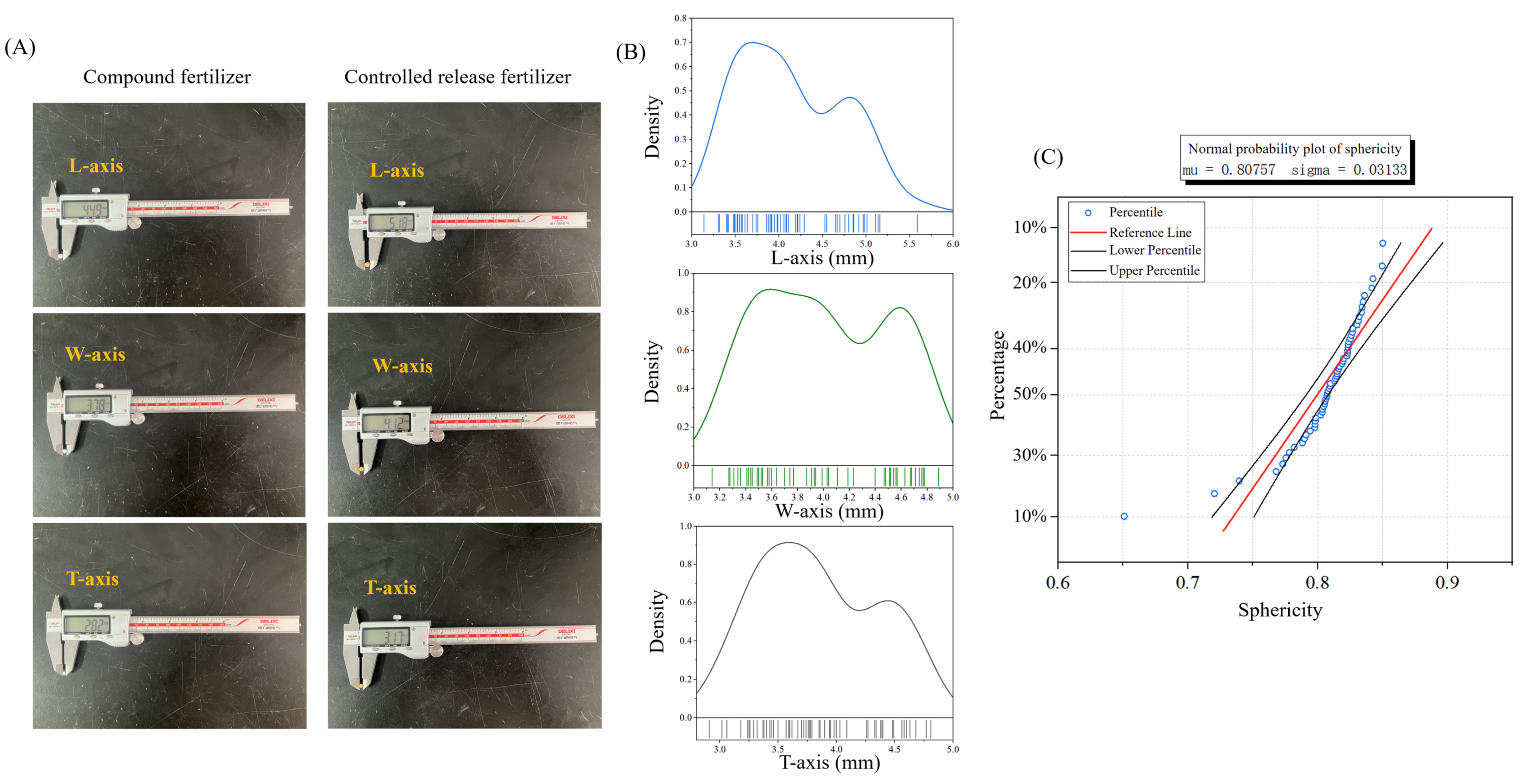
The diameter along the longitudinal axis of each particle was measured to determine the coating thickness (Figure 2A), and the results were used as input parameters for the geometric model in Section 2.4. As shown in Figure 2B,C, the triaxial dimensions of 60 randomly selected CRF particles followed an approximately normal distribution: L-axis dimensions were distributed between 3.5 and 5.0 mm for about 90% of samples, W-axis dimensions between 3.4 and 4.9 mm for approximately 94%, and T-axis dimensions between 3.2 and 4.7 mm for roughly 95%. Over 95% of the particles had equivalent diameters between 3.0 and 5.0 mm. The average L-axis length was 4.7 mm, W-axis length 3.8 mm, T-axis length 3.6 mm, and equivalent diameter 4.0 mm. The mean sphericity was 0.85. The calculation formulas are presented in Equations (1) and (2). These measurements provided key geometric input parameters for the modeling described in Section 2.4.
D = L × T × W 3
S = D L × 100 %
where D is the equivalent diameter (cm), L, T, W are the lengths in different directions (cm), and S is the sphericity.

2.3. Material Parameter Determination

Unlike conventional fertilizers, CRFs have distinct structural characteristics. The compound fertilizer core is coated to delay nutrient release [43,44,45,46]. Nutrients are released slowly through micropores in the coating, ensuring synchronization with crop needs [16,18,47]. The coating introduces material property differences between the core and the outer shell, which precludes the use of conventional sampling methods. Moreover, the protective role of the coating during mechanical application cannot be ignored. Therefore, CRF and compound fertilizer particles were sampled and tested separately.
Quasi-static compression tests were conducted to determine strength limits and elastic modulus using uniaxial planar compression. A universal testing machine (TOP Instrument, Hang’zhou, Zhejiang, China) was used, with a stress limit set to 500 MPa and a data acquisition frequency of 20 Hz. The loading and unloading speeds of the compression head were both set to 1 mm/min to better observe yield points. Each group of tests was repeated 10 times, and the average values were recorded (Figure 3A). The calculation formulas are provided in Equations (3)–(5). The drying method was used to measure moisture content. A drying oven (TOP Instrument, Hang’zhou, Zhejiang, China) was set at 80 °C for 2 min, with each experiment repeated 30 times and averaged (Figure 3B). The calculation formula is shown in Equation (6). Poisson’s ratio was determined using a particle analyzer (TOP Instrument, Hang’zhou, Zhejiang, China), with 10 repetitions per group and results averaged (Figure 3C). The density of particles was measured via the gravimetric and water displacement methods. A high-precision electronic balance (accuracy: 0.001 g) and a graduated cylinder (accuracy: 0.1 mL) were used to determine mass and volume, respectively. Each experiment was repeated 30 times and averaged (Figure 3D). The density was calculated using Equation (7).
σ max = F max A
E = σ ε
ε = Δ L L 0
W = m 1 m 2 m 1 × 100 %
ρ = M V
where σmax is the ultimate strength (MPa), Fmax is the maximum load when the sample fails (N), A is the initial cross-sectional area of the sample (m2), E is the elastic modulus (MPa), σ is the radial stress (MPa), ε is the radial strain, ΔL is the change in sample length (m), L0 is the original length of the sample (m), W is the moisture content (%), m1 is the mass of the sample before drying (g), m2 is the mass of the sample after drying (g), ρ is the sample density (g cm−3), M is the sample mass (g), and V is the sample volume (cm3).
Stress–strain curves were obtained from quasi-static experiments. The compression process included three stages: elastic, yield, and hardening. At the beginning of the test, stress increased linearly with the displacement of the compression head. As displacement continued, the stress–strain relationship became nonlinear, and stress rose until the sample reached its ultimate strength. At this point, the sample underwent plastic deformation and began to fracture. Subsequently, the force dropped rapidly, and the sample experienced further breakage and densification, marking the end of the quasi-static test for both CRF and compound fertilizer samples.
Ultimate strength and elastic modulus were calculated using Equations (3)–(5), and the results are summarized in Table 1. The sampling process emphasized the distinct mechanical properties of the coating and core materials. The CRF (coating) exhibited higher ultimate strength and elastic modulus than the compound fertilizer (core), indicating that the coating plays a significant protective role during mechanical fertilization (Figure 4A–C). Given the irreversible fragmentation of fertilizer particles affects nutrient release, equivalent stress was used in this study as a criterion for fracture assessment. Regions where the equivalent stress exceeded 8.25 MPa—the average ultimate strength of compound fertilizer—were defined as fractured zones. In addition, the average moisture contents of CRF and compound fertilizer were 5.7 ± 0.2% and 1.1 ± 0.2%, respectively (Figure 4D). The average densities were 1250 kg m−3 and 970 kg m−3 (Figure 4E), while the average Poisson’s ratios were 0.33 and 0.28 (Figure 4F). These material parameters formed the basis for fracture prediction and quantification in the finite element model.

2.4. Geometry Model Construction

The impact behavior of CRF particles was simulated using the FEM. Accurate modeling is critical to ensuring the reliability of FEM results. A double-layer finite element model was developed, representing the CRF particle as a “coating-core” structure. Multiple micropores were randomly distributed on the coating surface to simulate nutrient diffusion from the compound fertilizer core (Figure 5A). Based on the morphological measurements in Section 2.2, equivalent diameter and sphericity were selected as the fundamental parameters for model construction. Equivalent diameters of 3 mm, 4 mm, and 5 mm and sphericities of 0.6, 0.8, and 1.0 were chosen. The models were created in SolidWorks 2021 (https://www.solidworks.com/zh-hans accessed on 14 September 2025) (Figure 5B).

2.5. Finite Element Simulation Experiment

2.5.1. Material Properties and Meshing

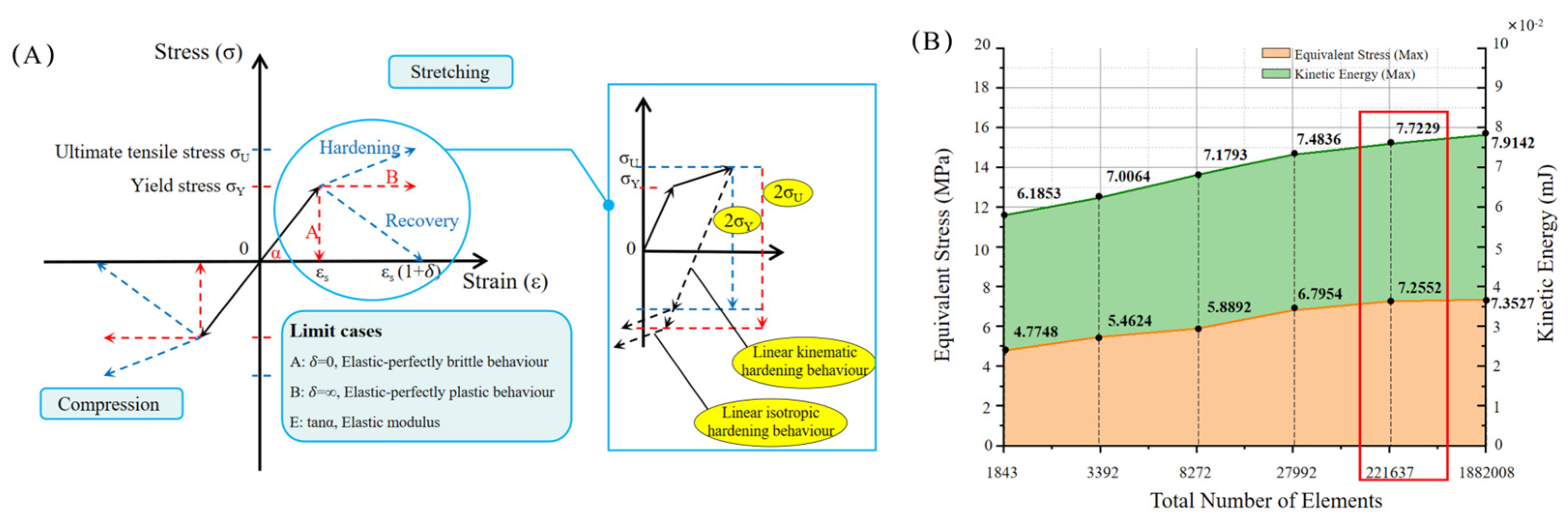
CRFs, like many fertilizer products, exhibit elasto-plastic and hardening behavior under external forces. This highlights the importance of defining material properties precisely in FEM simulations. The multi-scale FEM model developed in Section 2.4 was assigned an elasto-plastic bilinear isotropic hardening behavior for both the coating and the core (Figure 6A). Tetrahedral elements were used for meshing to better adapt to geometric edges while refining local elements and capturing regions with high stress gradients.
One key factor in FEM is mesh-size selection. Finer meshes yield more realistic results but require significantly more computational time and memory, especially in dynamic simulations. Therefore, a mesh sensitivity analysis was performed by applying different mesh sizes to the same simulation scenario (impact velocity = 3130 mm s−1, angle = 0 °, material = steel, equivalent diameter = 3 mm, sphericity = 0.6). The results indicated that a mesh size of 0.2 mm, with 39,911 nodes and 221,637 elements, provided optimal accuracy without significantly increasing computational cost (Figure 6B).

2.5.2. Simulation Experiment

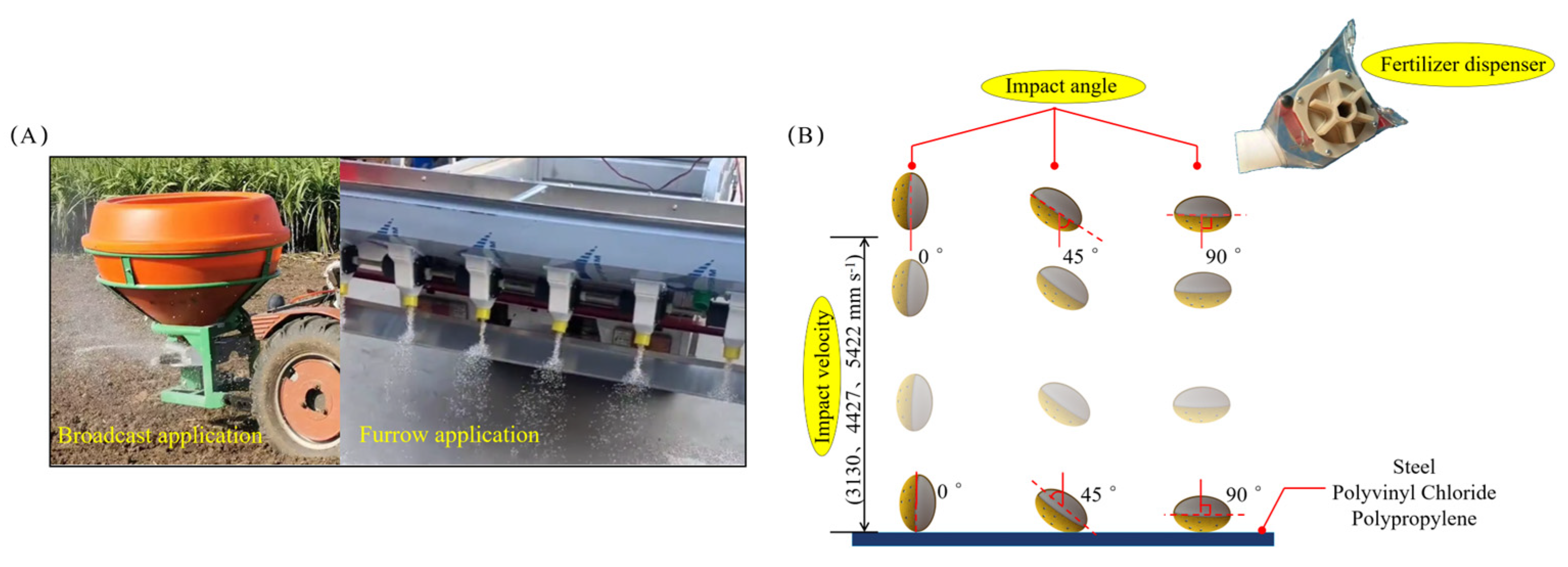
During fertilization, collisions between CRF particles and machine components (e.g., belts, outlets, and hoppers) are unavoidable (Figure 7A). The Explicit Dynamics module in ANSYS Workbench 2020R2 (https://www.ansys.com/ accessed on 14 September 2025) was used to simulate the dynamic behavior of CRF particles under impact. First, the mechanical parameters of the FEM model were defined using the multi-scale material data reported in Section 2.2 and Section 2.3. Second, initial simulation conditions were set, including impact velocities (3130, 4427, 5422 mm s−1), impact angles (0, 45, 90 °), impact materials (PP, PVC, Steel), equivalent diameters (3, 4, 5 mm), and sphericities (0.6, 0.8, 1.0), forming a full-factorial design with five factors (Figure 7B). Third, the inner surface of the coating (passive surface) and the outer surface of the core (active surface) were defined with a “bonded” contact to prevent relative motion or penetration between the layers. To improve contact stress resolution, face-to-face discretization was applied. The outer surface of the coating was defined as the active surface, and the upper surface of the impact material as the passive surface, with hard contact settings applied to prevent interpenetration. Fourth, mesh type and size were selected based on the sensitivity analysis in Section 2.5.1. Fifth, the solver was configured with 2000 sub-steps, a total simulation time of 0.03 s, and a gravitational acceleration of 9.8 m s−2. Sixth, total deformation, equivalent stress, and energy probes were added to the solution module, and a total of 243 simulation scenarios were executed.

2.5.3. Quantification of Crushing Volume

After the simulation experiments, the finite element model of the particles was analyzed to extract fracture characteristics, including fracture volume and fracture susceptibility. Considering the mechanism of particle failure and irreversible deformation, equivalent stress was adopted as the fracture evaluation index. Based on the material parameters of the controlled-release fertilizer (CRF) determined in Section 2.3, an equivalent stress of 8.25 MPa was defined as the fracture threshold. The fracture characteristics were quantified in terms of volume (Table 2). First, an isosurface exceeding 8.25 MPa was defined in ANSYS to extract the complete fracture region. Then, the volume was calculated using the evaluation function in SolidWorks 2021.

3. Results and Analysis

3.1. The Effect of Impact Velocity on Crushing Characteristics

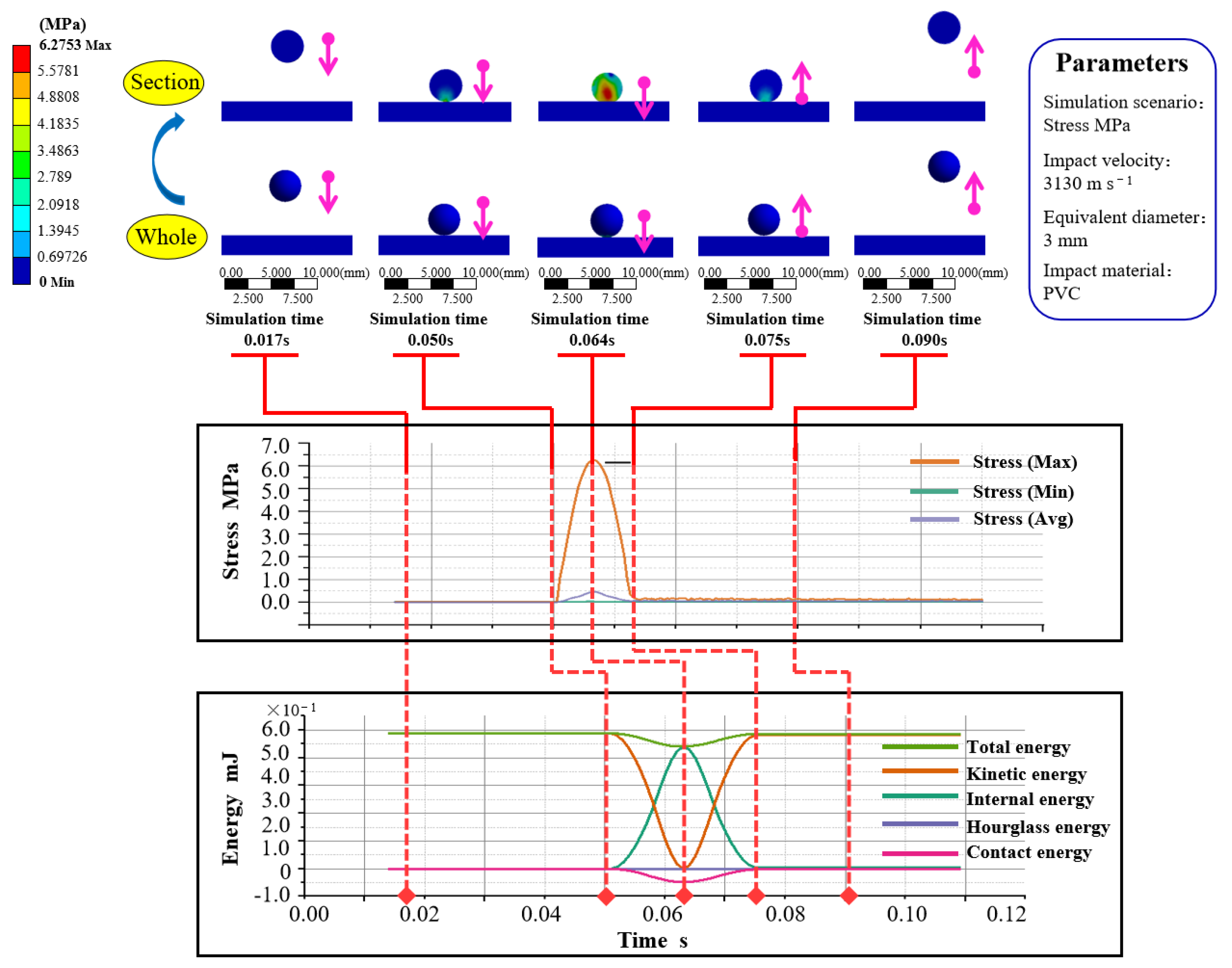
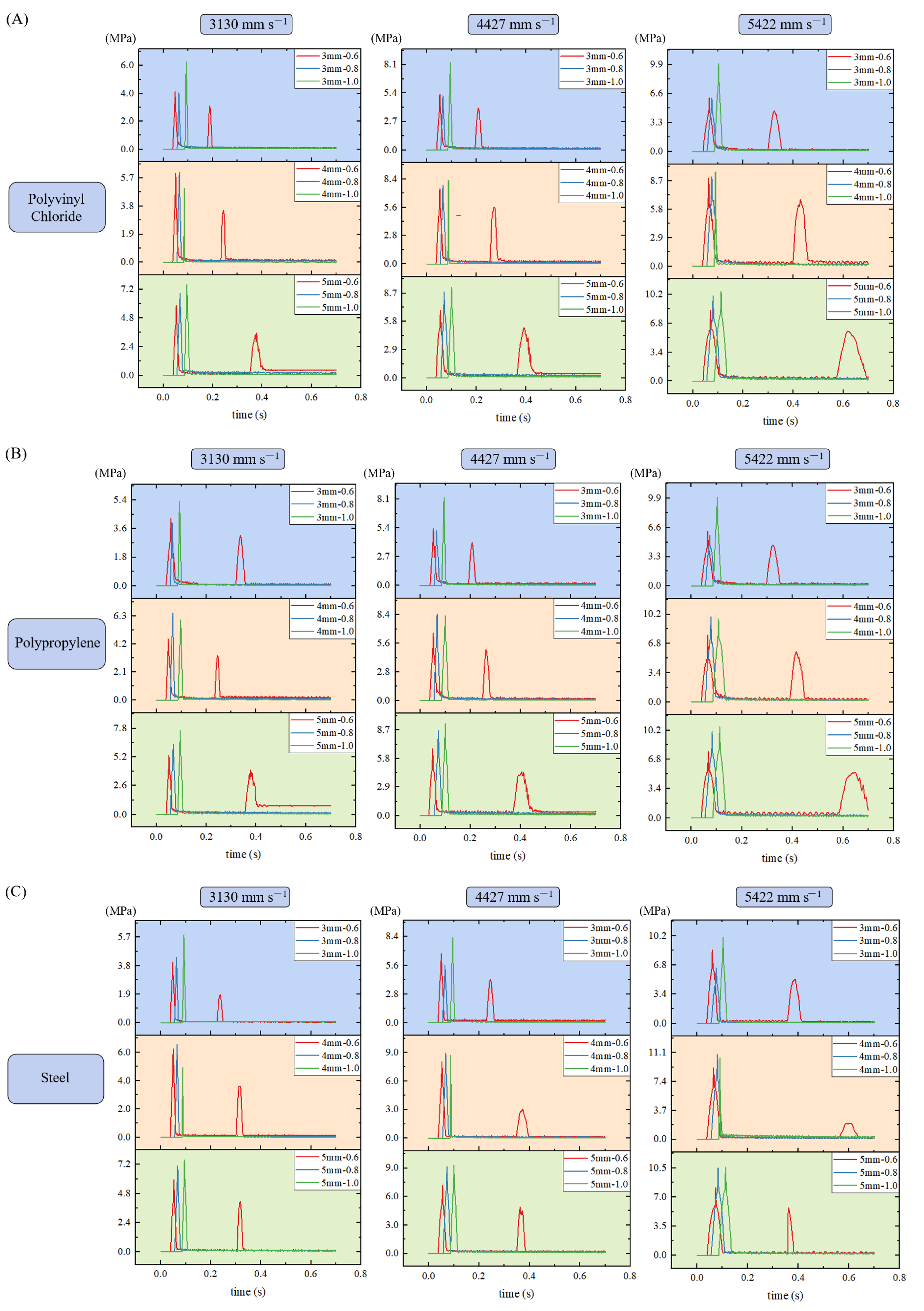
During mechanized fertilization, collisions between CRF particles and machine components cause core rupture, which accelerates the nutrient release rate. This alters the synchronization between nutrient release and crop demand, reducing the utilization efficiency of compound fertilizers and potentially causing environmental pollution due to excessive trace elements. Therefore, to elucidate the stress and energy transfer mechanisms during CRF collisions, a dynamic collision system was established at the particle level between the CRF and the applicator. This study analyzed five factors influencing fracture characteristics: impact velocity, impact angle, impact material, equivalent diameter, and sphericity. The simulation results showed that impact velocity had the most significant effect. As velocity increased, fracture characteristics became more pronounced. The distribution of equivalent stress and energy at both the surface and cross-section of the particles under 3130 mm s−1 impact velocity is shown in Figure 8. The cross-sectional view clearly illustrates the stress propagation and fracture zones. The entire process included a free-fall phase, contact phase, impact deformation phase, and rebound phase. At the moment of impact, the particle’s kinetic energy rapidly decreased while internal energy increased sharply. At 5.8 × 10⁻² s, kinetic energy equaled internal energy. At 6.4 × 10⁻² s, both reached their peak values: kinetic energy was 0 mJ, and internal energy was 0.64 mJ. At this moment, the maximum internal stress of 6.28 MPa appeared, concentrated at the contact region between the particle and the impact material. The maximum stress extended inward from the coating–core interface. After 6.4 × 10⁻² s, kinetic energy gradually increased, indicating the completion of the impact deformation stage. Subsequently, the equivalent stress in the particle exhibited periodic oscillations with a mean value of 0.12 MPa, primarily due to stress waves. After the impact load was removed, these stress oscillations resulted from reflection and interference. During the entire simulation, the system’s maximum total energy and internal energy were 0.69 mJ and 0.64 mJ, respectively. Energy analysis showed that hourglass energy was far less than 5% of the internal energy, confirming the rationality and accuracy of the finite element simulation parameters. At an impact velocity of 3130 mm s−1, particles began to fracture—this scenario corresponds to Case 10, where the fracture volume and fracture susceptibility were 1.34 mm3 and 7.04 mm3 mJ−1, respectively. Case 24, under the highest impact velocity, produced the maximum stress (22.31 MPa), fracture volume (12.88 mm3), and fracture susceptibility (9.06 mm3 mJ−1).

3.2. Effect of Equivalent Diameter and Sphericity on Crushing Characteristics

The particle’s equivalent diameter and sphericity also affected fracture characteristics. From the simulations at a 45° impact angle, the most severe fracture occurred at 5 mm diameter, followed by 4 mm, and then 3 mm. Given the stable density of CRF, particle diameter directly influenced mass and gravitational force, thereby affecting fracture characteristics. Moreover, fracture was most pronounced at a sphericity of 0.8, followed by 0.6, and least at 1.0. Sphericity affected the contact area upon impact, thus influencing internal stress. Although the internal energy peaks and timing were similar across different sphericity levels due to identical impact velocity, stress and fracture characteristics varied significantly. The maximum stress difference reached 13.09 MPa (for fractured particles), with the maximum difference in fracture volume reaching 11.99 mm3. This discrepancy was attributed to variations in contact area and loading direction. Particles with 0.8 sphericity exhibited wider and deeper stress distribution upon impact. This is related to particle geometry—compared to spherical shapes, polygonal particles are more prone to stress concentration due to poorer load distribution. Particles with 0.6 sphericity experienced multiple low-energy impacts in a short time, effectively dispersing stress. At the same equivalent diameter, more spherical particles had greater mass, leading to higher maximum stress post-impact. Overall, simulation results under 45° impact angle (Figure 9A,C) indicate that equivalent diameter and sphericity are critical determinants of fracture, with larger and less regular particles more susceptible to damage.

3.3. Effect of Impact Angle and Impacting Material on Crushing Characteristics

Fracture characteristics were also influenced by impact angle and material. Simulations showed that fracture was most severe at 0°, followed by 45°, and least at 90°. Although internal energy peaks and timing were similar under constant velocity, stress and fracture characteristics differed significantly: the maximum stress difference was 12.14 MPa, and the fracture volume difference was 11.13 mm3. At 0° impact, the particle’s small contact area and high curvature at both ends caused stress concentration. At 90°, increased contact area and curvature effectively dispersed stress. At 45°, irregular particle shapes led to multiple collisions shortly after the first impact, enhancing fracture. Steel impact material (Figure 10A) caused the most severe fracture, followed by PVC (Figure 10B) and PP (Figure 10C). The elastic modulus ratio between the impact material and CRF significantly influenced stress and fracture characteristics-the greater the ratio, the more pronounced the fracture. Stress cloud diagrams across different scenarios revealed variations in stress concentration patterns. These results suggest that CRFs should preferably be produced with spherical geometry and applied using optimized delivery paths, applicator materials, and discharge methods to minimize mechanical damage.

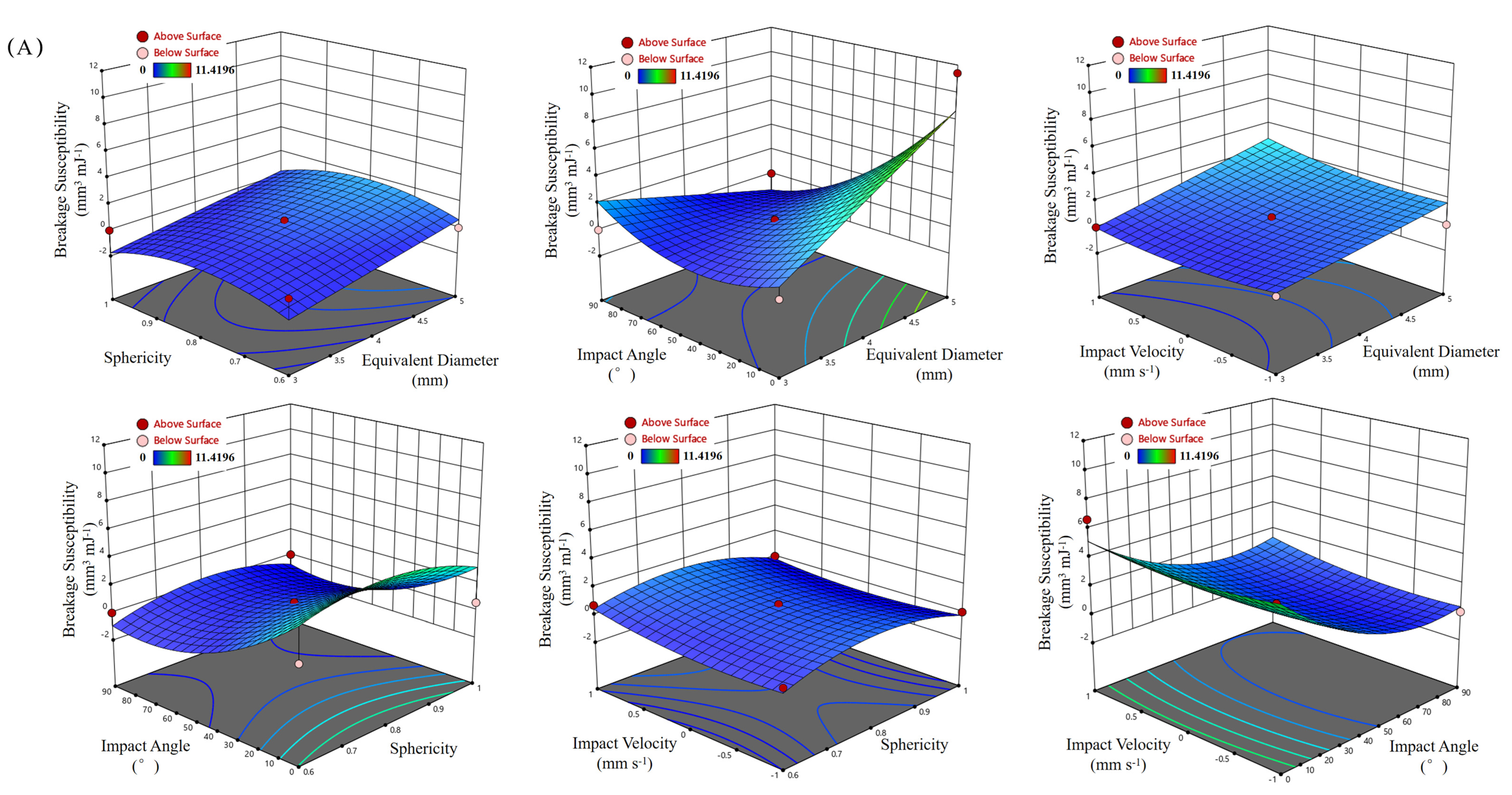
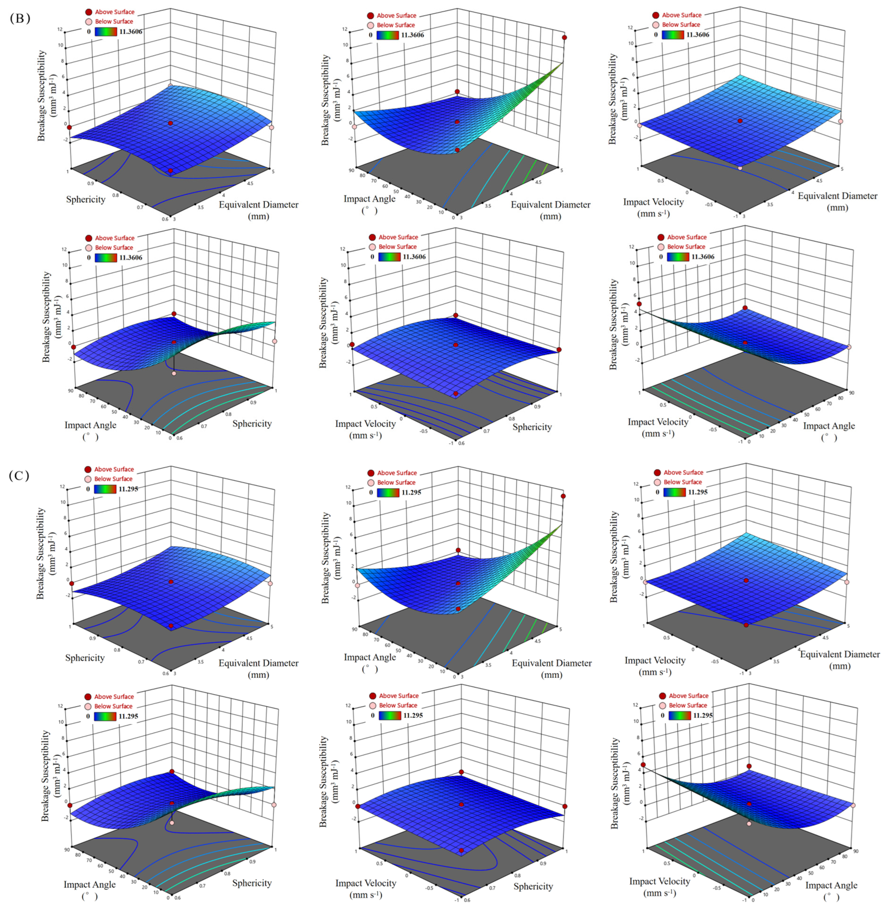
3.4. Results of Response Surface Analysis

To predict the fragmentation characteristics of CRF particles during impact, response surface methodology (RSM) was employed to analyze the simulation results. Corresponding regression models and response surfaces were established. The quality of the regression models was evaluated using the coefficient of determination (R2). Equations (8)–(10) represent the regression models with fragmentation susceptibility as the response variable. For impact materials of steel (Figure 11A), PVC (Figure 11B), and PP (Figure 11C), the R2 values were 0.8521, 0.8801, and 0.8642, respectively. These values indicate that the RSM-based regression models achieved a fitting accuracy of over 85.21% in predicting the fragmentation susceptibility of CRF particles. However, to further verify the agreement between FEM and real-world experiments (RE), a series of comparative validation experiments was subsequently conducted.
Y Steel = 29.54311   +   3.85710 D   +   48.60325 S   +   0.102104 A     0.741783 V     0.063442 DA +   0.343100 DV   +   0.023506 SA     0.883250 SV   +   0.006308 AV   +   0.007975 D 2     31.44250 S 2 +   0.000935 A 2   +   0.480150 V 2
Y PVC = 11.07573     1.81827 D   +   34.12217 S   +   0.035499 A   +   0.181600 V   +   1.40150 DS     0.048790 DA +   0.134550 DV   +   0.032014 SA     0.826250 SV   +   0.002573 AV   +   0.487750 D 2     25.89344 S 2   +   0.000954 A 2 +   0.135887 V 2
Y PP = 7.61230     2.02352 D   +   29.27983 S     0.004285 A     0.389233 V     0.048489 DA   +   0.275300 DV +   0.081133 SA     0.008450 AV   +   0.633992 D 2 21.34240 S 2   +   0.000994 A 2   +   0.035004 V 2
where YSteel, YPVC, YPP is the empirical breakage susceptibility, D is the equivalent diameter (mm), S is the sphericity, A is the impact angle (°), V is the impact velocity (mm s−1).
Although the regression models developed based on RSM exhibited fitting accuracies above 85.21% for fragmentation susceptibility, validation experiments (Figure 12) were conducted to further demonstrate the reliability of the simulation results. Ten sets of comparative experiments were randomly selected within the experimental range described in Section 2.5.2. CRF particles of different particle sizes were obtained using sieves with varying pore sizes. Each group of experiments was repeated three times, and the average values were calculated. The experimental design and corresponding results are summarized in Table 3.
Since it is difficult to directly determine the energy variation in CRF particles in physical experiments, the fragmentation rate Rc was characterized by measuring the mass of fragmented particles. Given the relatively high toughness of the CRF coating, particles often retain structural integrity even after cracking. As the volume change in the particles after fracture is negligible, the fragmented mass was used as a more practical and quantifiable indicator. Specifically, the fragmentation rate was calculated as the ratio of the fragmented particle mass Qc (defined as particles with a mass reduction of more than 10%) to the total mass Qo of all particles in a given group. Comparison between simulation and experimental results revealed a maximum deviation in fragmentation rate of 11.47%. Under dynamic loading conditions, CRF particles typically exhibit strain-rate hardening effects. The accumulation of dislocation interactions increases the resistance to deformation, meaning that post-failure deformation does not necessarily lead to a significant reduction in particle stiffness. Therefore, although there are slight differences in the fragmentation characteristics between simulation and experimental results, their fragmentation behavior remains consistent. Considering the complexity and cost of accurately measuring fertilizer particle fragmentation characteristics, the observed deviation is deemed acceptable. Overall, the comparison results validate the correctness of the regression model established for predicting CRF particle fragmentation characteristics.

4. Discussion

Despite the critical role of structural integrity in maintaining the efficacy of CRFs, quantitative investigations into the dynamic fragmentation behavior of fertilizer particles remain limited. Previous studies have predominantly relied on quasi-static compression experiments or discrete element method simulations to examine the crushing behavior of fertilizer particles. While these methods offer insight into post-compression behavior, they fall short in representing the high-velocity, high-energy impact scenarios commonly encountered during mechanical field applications. More importantly, they are unable to capture the complex evolution of internal stress and strain fields that govern the onset and progression of particle failure.
To address these gaps, our study adopts an explicit dynamic FEM framework, which has proven effective in simulating the impact responses of fragile and composite materials such as fruits, pharmaceutical tablets, and concrete [33,34,36,37]. For example, Celik used FEM to simulate damage patterns in apples during postharvest handling, offering insight into localized stress distributions. Similarly, Hou developed a multi-scale FEM model for blueberries, enabling the prediction of mechanical damage susceptibility during harvesting. These efforts underscore the FEM’s capacity to capture stress wave propagation, crack initiation, and fracture development in complex biological and composite systems. Notably, such modeling approaches have rarely been applied to CRF granules, whose unique material composition and mechanical properties necessitate customized modeling strategies. By constructing a high-fidelity FEM simulation framework calibrated with experimental mechanical parameters, our study provides a comprehensive analysis of CRF fragmentation susceptibility under various impact conditions. Specifically, we introduce the concept of fragmentation susceptibility—defined as the ratio of fragmented volume to peak impact energy—as a novel and quantitative index for evaluating particle breakage behavior. A higher fragmentation susceptibility index indicates greater coating brittleness and a higher likelihood of premature nutrient release. Such mechanical vulnerability can accelerate nutrient leaching and disrupt the synchronization between nutrient supply and plant uptake, ultimately reducing fertilizer efficiency and increasing the risk of eutrophication. The mass-based fragmentation experiments conducted in this study serve as a key means to validate the credibility of the finite element analysis, while the high consistency between experimental observations and FEM predictions further confirms the reliability of the theoretical index of fragmentation susceptibility. Therefore, enhancing the mechanical resistance of controlled-release fertilizers is not only a technical optimization objective but also a crucial requirement for achieving sustainable horticultural production (1–10).
Our simulations reveal that fragmentation susceptibility increases linearly with impact velocity, aligning with the basic principles of kinetic energy transfer during high-speed collisions. Moreover, the modulus ratio between the impactor and CRF particle was found to play a decisive role in fragmentation suppression, with different materials exhibiting distinct critical velocities. These results are consistent with studies in pharmaceutical coating rupture and concrete failure, where interface material mismatch significantly affects stress concentration and damage initiation [9,35]. Furthermore, the simulation shows that the impact angle significantly influences fragmentation outcomes. CRF granules experience the most severe damage under direct (0°) impacts, likely due to the maximized normal force component. Particle morphology also affects fragmentation: particles with larger equivalent diameters and lower sphericity are more prone to breakage, likely due to their reduced ability to uniformly disperse impact stress. This observation echoes findings from fruit and tablet studies, where geometry directly influences mechanical resilience [34,36].
Importantly, the consistency between our FEM-based predictions and experimental results—with error rates below 11.47—demonstrates the robustness and practical relevance of the proposed modeling approach. Compared to DEM simulations, which typically rely on empirical contact laws and idealized particle shapes, FEM provides a more detailed and physics-based insight into the internal failure mechanisms of CRF particles. It should be noted that the use of a single fracture criterion (8.25 MPa) and the simplified bilinear hardening behavior may not fully capture the microcrack coalescence process in heterogeneous coatings. Nevertheless, the consistent agreement between simulated and experimental fragmentation rates validates the practical adequacy of these simplifications (1–9). This capability is particularly important as agricultural mechanization trends toward higher speed and efficiency, where precise control over nutrient release becomes both a technical challenge and a sustainability imperative.

5. Conclusions

This study proposed a finite element-based method to predict and quantify fragmentation characteristics of CRF particles during mechanized fertilization. A variable-speed fertilizer distributor was also used to verify the validity of the approach. Five key influencing factors were analyzed: equivalent diameter, sphericity, impact velocity, impact angle, and impact material. Compared with discrete element models, this approach enables more intuitive insight into internal stress evolution and energy conversion during fragmentation, which is vital for clean and efficient fertilization. The quantitative metric of “fragmentation susceptibility” proposed in this study not only helps predict the breakage risk of controlled-release fertilizers during mechanized application at the simulation level but also serves as an engineering design parameter for formula and process improvements, product quality control, and application equipment optimization. By inhibiting fragmentation during the packaging–transportation–application chain, the expected release cycle of controlled-release fertilizers can be maintained, thereby improving field nutrient use efficiency and reducing early leaching and environmental externalities. Therefore, controlling the physical integrity of particles should be key to promoting more sustainable horticultural production (2–13). The main conclusions are as follows:
The mechanical fragmentation mechanism of CRF particles and their sensitivity to various factors were clarified. Fragmentation susceptibility was proposed as a key evaluation indicator. Fragment volume and susceptibility were quantitatively determined based on stress thresholds and energy analysis.
Fragmentation susceptibility increased linearly with impact velocity. The Young’s modulus ratio between CRF and impact material significantly affected the critical fracture speed. A 0° impact angle produced the most severe fragmentation. Larger particle diameters and lower sphericity promoted fragmentation, indicating that particle morphology greatly influences stress dispersion.
Comparative experiments showed that within typical operational ranges, the fragmentation rate difference between simulation and real tests remained within 11.47%, demonstrating the model’s predictive accuracy. The proposed method supports clean and efficient mechanized application of controlled-release fertilizers. Moreover, the response surface regression models developed in this study provide a quantitative predictive framework for estimating fragmentation susceptibility under varying operating conditions, offering practical value for fertilizer design and mechanical application optimization (1–11).

Author Contributions

Conceptualization, Z.C.; Methodology, Z.C.; Software, Z.C. and Y.W.; Investigation, Z.C., X.C. and L.J.; Writing—original draft, Z.C.; Validation, Y.W.; Visualization, Y.W. and L.J.; Formal analysis, Y.W.; Data curation, X.C. and L.J.; Writing-review and editing, L.S.; Project administration, H.Z. and J.W.; Funding acquisition, H.Z. and J.W.; Resources, H.Z. and J.W. All authors have read and agreed to the published version of the manuscript.

Funding

This research was funded by the Shandong Province Key R&D Plan (2022CXGC020706), National Natural Science Foundation of China (32201682), China Postdoctoral Science Foundation funded by the General Funding Project (2024M751869), Postdoctoral Innovation Project of Shandong Province (SDCX-ZG-202400200), China Agriculture Research System (CARS-27), Supported By Young Talent of Lifting engineering for Science and Technology in Shandong (SDAST2024QTA050), Shandong Province “University Youth Innovation Team” Program (2023KJ160).

Data Availability Statement

The original contributions presented in this study are included in the article. Further inquiries can be directed to the corresponding authors.

Conflicts of Interest

The authors declare no conflicts of interest.

References

  1. Guo, L.; Zhao, S.; Song, Y.; Tang, M.; Li, H. Green Finance, Chemical Fertilizer Use and Carbon Emissions from Agricultural Production. Agriculture 2022, 12, 313. [Google Scholar] [CrossRef]
  2. Govil, S.; Long, N.; Escribà-Gelonch, M.; Hessel, V. Controlled-release fertiliser: Recent developments and perspectives. Ind. Crops Prod. 2024, 219, 119160. [Google Scholar] [CrossRef]
  3. Singh, A. Bio-based materials for fabrication of controlled-release coated fertilizers to enhance soil fertility: A review. Next Mater. 2025, 8, 100701. [Google Scholar] [CrossRef]
  4. Sun, X.; Niu, L.; Zhang, H.; Wang, Q.; Zhou, W.; Tang, H.; Wang, J. Exploring sustainable agriculture: Investigating the impact of controlled release fertilizer damage through bonded particle modeling. J. Clean. Prod. 2024, 468, 143095. [Google Scholar] [CrossRef]
  5. Horabik, J.; Molenda, M. Parameters and contact models for DEM simulations of agricultural granular materials: A review. Biosyst. Eng. 2016, 147, 206–225. [Google Scholar] [CrossRef]
  6. Luo, T.; Ooi, E.; Chan, A.; Fu, S. The combined scaled boundary finite-discrete element method: Grain breakage modelling in cohesion-less granular media. Comput. Geotech. 2017, 88, 199–221. [Google Scholar] [CrossRef]
  7. Gao, X.; Cui, T.; Zhou, Z.; Yu, Y.; Xu, Y.; Zhang, D.; Song, W. DEM study of particle motion in novel high-speed seed metering device. Adv. Powder Technol. 2021, 32, 1438–1449. [Google Scholar] [CrossRef]
  8. Ding, S.; Bai, L.; Yao, Y.; Yue, B.; Fu, Z.; Zheng, Z.; Huang, Y. Discrete element modelling (DEM) of fertilizer dual-banding with adjustable rates. Comput. Electron. Agric. 2018, 152, 32–39. [Google Scholar] [CrossRef]
  9. Chen, Z.; Wang, G.; Xue, D. An approach to calibration of BPM bonding parameters for iron ore. Powder Technol. 2021, 381, 245–254. [Google Scholar] [CrossRef]
  10. Gao, X.; Xie, G.; Xu, Y.; Yu, Y.; Lai, Q. Application of a staggered symmetrical spiral groove wheel on a quantitative feeding device and investigation of particle motion characteristics based on DEM. Powder Technol. 2022, 407, 117650. [Google Scholar] [CrossRef]
  11. Ren, C.; Jin, S.; Wu, Y.; Zhang, B.; Kanter, D.; Wu, B.; Xi, X.; Zhang, X.; Chen, D.; Xu, J.; et al. Fertilizer overuse in Chinese smallholders due to lack of fixed inputs. J. Environ. Manag. 2021, 293, 112913. [Google Scholar] [CrossRef]
  12. Sane, M.; Hajek, M.; Nwaogu, C.; Purwestri, R. Subsidy as an economic instrument for environmental protection: A case of global fertilizer use. Sustainability 2021, 13, 9408. [Google Scholar] [CrossRef]
  13. Bora, K. Spatial patterns of fertilizer use and imbalances: Evidence from rice cultivation in India. Environ. Chall. 2022, 7, 100452. [Google Scholar] [CrossRef]
  14. Dong, J.; Zhang, S.; Zheng, Z.; Wu, J.; Huang, Y.; Gao, X. Development of a novel perforated type precision metering device for efficient and cleaner production of maize. J. Clean. Prod. 2024, 443, 140928. [Google Scholar] [CrossRef]
  15. Lu, C.; Luo, J.; Sheng, T.; Xie, Y.; Xian, Y.; Jiang, Y.; Li, X.; Yao, M. Diazotrophic communities shift with organic fertilizer substitution and growth stages in tomato field soil. Eur. J. Soil Biol. 2025, 126, 103746. [Google Scholar] [CrossRef]
  16. Ni, X.; Wu, Y.; Wu, Z.; Wu, L.; Qiu, G.; Yu, L. A novel slow-release urea fertiliser: Physical and chemical analysis of its structure and study of its release mechanism. Biosyst. Eng. 2013, 115, 274–282. [Google Scholar] [CrossRef]
  17. Gil-Ortiz, R.; Naranjo, M.Á.; Ruiz-Navarro, A.; Atares, S.; García, C.; Zotarelli, L.; San Bautista, A.; Vicente, O. Enhanced Agronomic Efficiency Using a New Controlled-Released, Polymeric-Coated Nitrogen Fertilizer in Rice. Plants 2020, 9, 1183. [Google Scholar] [CrossRef] [PubMed]
  18. Lawrencia, D.; Wong, S.K.; Low, D.Y.S.; Goh, B.H.; Goh, J.K.; Ruktanonchai, U.R.; Soottitantawat, A.; Lee, L.H.; Tang, S.Y. Controlled Release Fertilizers: A Review on Coating Materials and Mechanism of Release. Plants 2021, 10, 238. [Google Scholar] [CrossRef]
  19. Ghodki, B.; Kumar, K.; Goswami, T. Modeling breakage and motion of black pepper seeds in cryogenic mill. Adv. Powder Technol. 2018, 29, 1055–1071. [Google Scholar] [CrossRef]
  20. Long, S.; Xu, S.; Zhang, Y.; Zhang, J.; Wang, J. Effect of modeling parameters on the mechanical response of macroscopic crushing of agglomerate. Powder Technol. 2022, 408, 117720. [Google Scholar] [CrossRef]
  21. Shi, Q.; Sakai, M. Recent progress on the discrete element method simulations for powder transport systems: A review. Adv. Powder Technol. 2022, 33, 103664. [Google Scholar] [CrossRef]
  22. Karayel, D.; Wiesehoff, M.; Özmerzi, A.; Müller, J. Laboratory measurement of seed drill seed spacing and velocity of fall of seeds using high-speed camera system. Comput. Electron. Agric. 2006, 50, 89–96. [Google Scholar] [CrossRef]
  23. Liu, J.; Yang, Y.; Gao, B.; Li, Y.; Xie, J. Bio-based elastic polyurethane for controlled-release urea fertilizer: Fabrication, properties, swelling and nitrogen release characteristics. J. Clean. Prod. 2019, 209, 528–537. [Google Scholar] [CrossRef]
  24. Cai, R.; Zhao, Y. An experimentally validated coarse-grain DEM study of monodisperse granular mixing. Powder Technol. 2020, 361, 99–111. [Google Scholar] [CrossRef]
  25. Wang, L.; Cong, J.; Liu, Z.; Liao, Q.; Liao, Y.; Shi, Y.; Wang, X. Design and experimental analysis of the air-assisted fertilizer apparatus’s distributor using DEM-CFD and high-speed photography. Comput. Electron. Agric. 2025, 237 Pt B, 110653. [Google Scholar] [CrossRef]
  26. Lei, X.; Liao, Y.; Zhang, Q.; Wang, L.; Liao, Q. Numerical simulation of seed motion characteristics of distribution head for rapeseed and wheat. Comput. Electron. Agric. 2018, 150, 98–109. [Google Scholar] [CrossRef]
  27. Chen, H.; Liu, W.; Gao, L.; Liao, Y.; Li, Q.; Liao, Q. An adaptive spacing of root-zone hole fertilization to improve production and fertilizer utilization of rapeseed. J. Sci. Food Agric. 2024, 104, 6276–6288. [Google Scholar] [CrossRef]
  28. Li, X.; Zhu, X.; Liang, J.; Zhu, Z.; Li, B.; Guo, H. Mechanisation of ring-furrow fertiliser application for orchards: A multi-segment arc trajectory and its control method. Biosyst. Eng. 2025, 257, 104213. [Google Scholar] [CrossRef]
  29. Xiao, Y.; Chen, Z.; Zhou, J.; Leng, Y.; Xia, R. Concrete plastic-damage factor for finite element analysis: Concept, simulation, and experiment. Adv. Mech. Eng. 2017, 9, 1687814017719642. [Google Scholar] [CrossRef]
  30. Partheniadis, I.; Terzi, V.; Nikolakakis, I. Finite element analysis and modeling in pharmaceutical tableting. Pharmaceutics 2022, 14, 673. [Google Scholar] [CrossRef]
  31. Chen, Z.; Sun, L.; Jing, L.; Cao, X.; Wang, Y.; Liu, J.; Zhang, H.; Wang, J. Predicting and quantifying damage characteristics in mechanized harvesting: A collision-based study of apples. Postharvest Biol. Technol. 2025, 227, 113586. [Google Scholar] [CrossRef]
  32. Guo, J.; Yang, Z.; Karkee, M.; Han, X.; Duan, J.; He, Y. Dynamic finite element simulation of the collision behavior and multi-parameter quantitative characterization of the damage degree of banana fruit in the post-harvest operations. Postharvest Biol. Technol. 2025, 219, 113284. [Google Scholar] [CrossRef]
  33. Celik, H.; Rennie, A.; Akinci, I. Deformation behaviour simulation of an apple under drop case by finite element method. J. Food Eng. 2011, 104, 293–298. [Google Scholar] [CrossRef]
  34. Hou, J.; Park, B.; Li, C.; Wang, X. A multiscale computation study on bruise susceptibility of blueberries from mechanical impact. Postharvest Biol. Technol. 2024, 208, 112660. [Google Scholar] [CrossRef]
  35. Yang, Y.; Li, J.; Miao, K.; Shan, W.; Tang, L.; Yu, H. Simulation and evaluation of tablet-coating burst based on finite element method. Drug Dev. Ind. Pharm. 2016, 42, 1384–1392. [Google Scholar] [CrossRef]
  36. Okada, N.; Hayashi, Y.; Onuki, Y.; Miura, T.; Obata, Y.; Takayama, K. Mechanical stress simulation of scored tablets based on the finite element method and experimental verification. Chem. Pharm. Bull. 2016, 64, 1142–1148. [Google Scholar] [CrossRef]
  37. Chen, L.; Liu, D.; Lei, M.; Zhang, Y.; Zhao, T.; Zheng, Y. The study on the constitutive model of concrete for explicit dynamic of ABAQUS based on damage energy. Adv. Mater. Sci. Eng. 2022, 9, 1914314. [Google Scholar] [CrossRef]
  38. Aikins, K.; Ucgul, M.; Barr, J.; Awuah, E.; Antille, D.; Jensen, T.; Desbiolles, J. Review of Discrete Element Method Simulations of Soil Tillage and Furrow Opening. Agriculture 2023, 13, 541. [Google Scholar] [CrossRef]
  39. Li, J.; Xu, M.; Xiang, L.; Chen, D.; Zhuang, W.; Yin, X.; Li, Z. Foundation models in smart agriculture: Basics, opportunities, and challenges. Comput. Electron. Agric. 2024, 222, 109032. [Google Scholar] [CrossRef]
  40. Kalia, A.; Sharma, S.; Kaur, H.; Kaur, H. Chapter 5—Novel nanocomposite-based controlled-release fertilizer and pesticide formulations: Prospects and challenges. Multifunct. Hybrid Nanomater. Sustain. Agri-Food Ecosyst. 2020, 99–134. [Google Scholar] [CrossRef]
  41. Vejan, P.; Khadiran, T.; Abdullah, R.; Ahmad, N. Controlled release fertilizer: A review on developments, applications and potential in agriculture. J. Control. Release 2021, 339, 321–334. [Google Scholar] [CrossRef]
  42. Kassem, I.; Ablouh, E.; Bouchtaoui, F.; Jaouahar, M.; Achaby, M. Polymer coated slow/controlled release granular fertilizers: Fundamentals and research trends. Prog. Mater. Sci. 2024, 144, 101269. [Google Scholar] [CrossRef]
  43. Liu, Y.; Gao, D.; Li, X.; Qin, X.; Li, H.; Hang, L. Investigating the jet comminuting process in cuttings transport by coupling the CFD/DEM method and bonded-particle model. SPE J. 2019, 24, 2020–2032. [Google Scholar] [CrossRef]
  44. Gil-Ortiz, R.; Naranjo, M.; Ruiz-Navarro, A.; Caballero-Molada, M.; Atares, S.; García, C.; Vicente, O. New eco-friendly polymeric-coated urea fertilizers enhanced crop yield in wheat. Agronomy 2020, 10, 438. [Google Scholar] [CrossRef]
  45. Ain, N.; Naveed, M.; Hussain, A.; Mumtaz, M.; Rafique, M.; Bashir, M.; Alamri, S.; Siddiqui, M. Impact of coating of urea with bacillus-augmented zinc oxide on wheat grown under salinity stress. Plants 2020, 9, 1375. [Google Scholar] [CrossRef]
  46. Marcińczyk, M.; Oleszczuk, P. Biochar and engineered biochar as slow- and controlled-release fertilizers. J. Clean. Prod. 2022, 339, 130685. [Google Scholar] [CrossRef]
  47. Fertahi, S.; Ilsouk, M.; Zeroual, Y.; Oukarroum, A.; Barakat, A. Recent trends in organic coating based on biopolymers and biomass for controlled and slow release fertilizers. J. Control. Release 2021, 330, 341–361. [Google Scholar] [CrossRef] [PubMed]
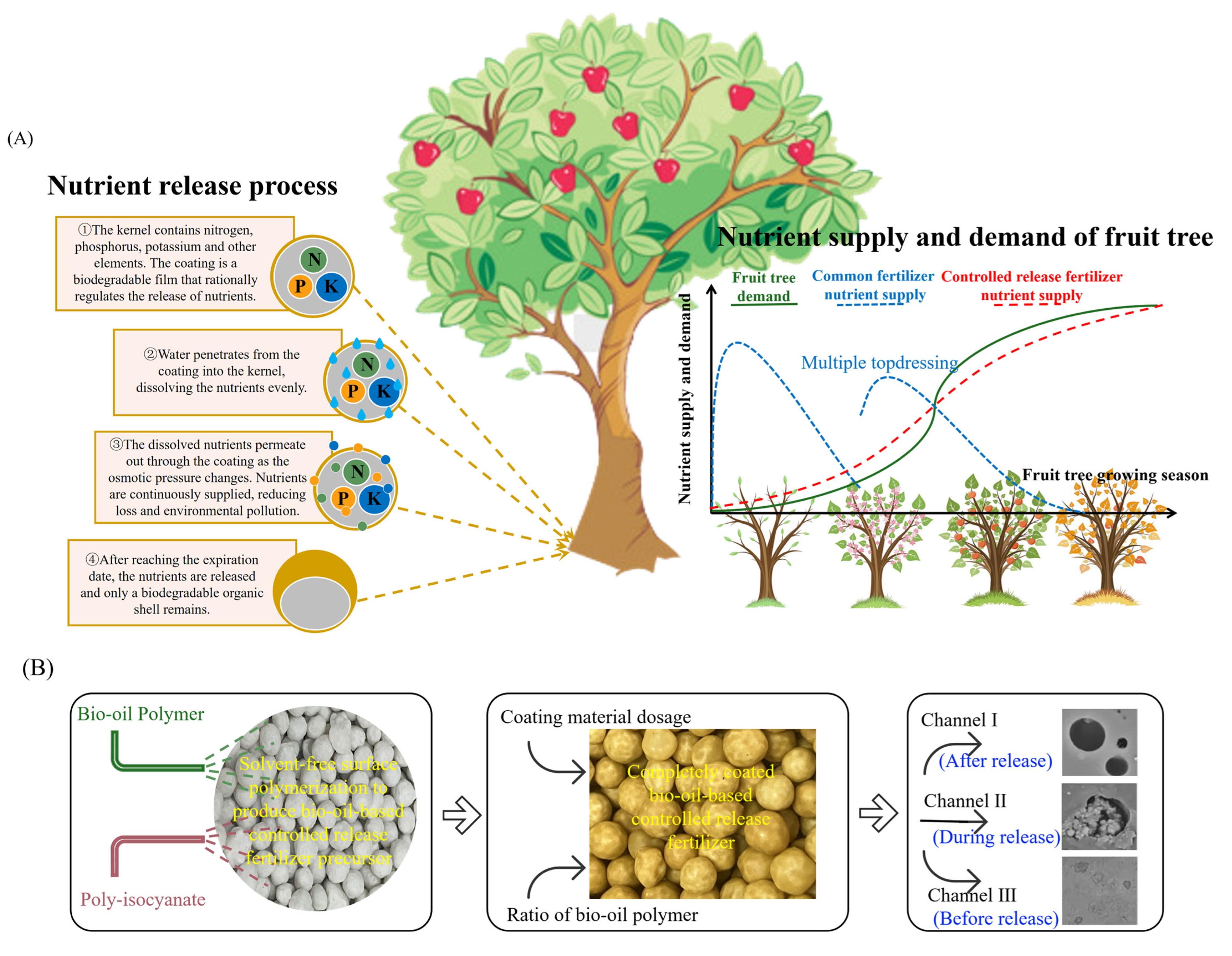
Figure 1. CRF Preparation and Action Principle. (A) Nutrient Release Mechanism of Controlled-Release Fertilizer. (B) Process Flowchart for Controlled-Release Fertilizer Production.
Horticulturae 11 01215 g001
Figure 2. Statistical Chart of Fertilizer Particle Morphology Parameters. (A) Particle Axis Length Measurement Process. (B) Particle Axis Length Data. (C) Particle Sphericity Data.
Horticulturae 11 01215 g002
Figure 3. Experiment on Determination of Parameters of Fertilizer Granular Materials. (A) Quasi-static Experiment. (B) Moisture Content Experiment. (C) Poisson’s Ratio Experiment. (D) Density Experiment.
Horticulturae 11 01215 g003
Figure 4. Statistical Chart of Material Parameters. (A) Controlled-Release Fertilizer Stress-Strain Curve. (B) Compound Fertilizer Stress-Strain Curve. (C) Equivalent Stress and Ultimate Strength of Fertilizer Granules. (D) Moisture Content of Fertilizer Granules. (E) Density of Fertilizer Granules. (F) Poisson’s Ratio of Fertilizer Granules.
Horticulturae 11 01215 g004
Figure 5. Geometric Model of CRF Particles. (A) Nutrient Release Mechanism of Controlled-Release Fertilizer. (B) Construction of a Geometric Model for Controlled-Release Fertilizer Particles.
Horticulturae 11 01215 g005
Figure 6. Material Properties and Mesh Generation of FEM. (A) Bilinear Isotropic Hardening Model. (B) Mesh Quality Analysis.
Horticulturae 11 01215 g006
Figure 7. Schematic Diagrams of CRF Particle Impact. (A) Mechanized Fertilization Operation Scene. (B) Simulation Experiment Scene.
Horticulturae 11 01215 g007
Figure 8. Contour Plots of Equivalent Stress and Energy Changes.
Horticulturae 11 01215 g008
Figure 9. Effect of Equivalent Diameter and Sphericity on Equivalent Stress. (A) Response of Crushing Characteristics to Shape Characteristics and Polyvinyl Chloride. (B) Response of Crushing Characteristics to Shape Characteristics and Polypropylene. (C) Response of Crushing Characteristics to Shape Characteristics and Steel.
Horticulturae 11 01215 g009
Figure 10. Contour Plots of Stress and Deformation Progression in CRF Particles. (A) Effects of Impact Angle and Impact Material(Steel) on Stress Progression and Crushing Characteristics. (B) Effects of Impact Angle and Impact Material(Polyvinyl Chloride) on Stress Progression and Crushing Characteristics. (C) Effects of Impact Angle and Impact Material(Polypropylene) on Stress Progression and Crushing Characteristics.
Horticulturae 11 01215 g010
Figure 11. Response Surface of Crushing Susceptibility for CRF Particles. (A) Response Surface Analysis of Factors Affecting Crushing Susceptibility When the Impact Material is Steel. (B) Response Surface Analysis of Factors Affecting Crushing Susceptibility When the Impact Material is Polyvinyl Chloride. (C) Response Surface Analysis of Factors Affecting Crushing Susceptibility When the Impact Material is Polypropylene.
Horticulturae 11 01215 g011aHorticulturae 11 01215 g011b
Figure 12. Physical Experiment Scenario.
Horticulturae 11 01215 g012
Table 1. Material Parameters.
ParameterSampleMean
Elastic modulusControlled-release fertilizer36.23 MPa
Compound fertilizer29.81 MPa
Strength limitControlled-release fertilizer11.74 MPa
Compound fertilizer8.25 MPa
DensityControlled-release fertilizer1250 kg m−3
Compound fertilizer970 kg m−3
Moisture contentControlled-release fertilizer5.7 ± 0.2%
Compound fertilizer1.1 ± 0.2%
Poisson’s ratioControlled-release fertilizer0.33
Compound fertilizer0.28
Table 2. Results of Breakage Susceptibility Analysis.
Impact MaterialEquivalent DiameterSphericityImpact AngleImpact VelocityEquivalent StressBreakage VolumeBreakage Susceptibility
(mm)(°)(mm s−1)(MPa)(mm3)(mm3 mJ−1)
Steel30.6044278.71999.30 × 10−26.30 × 10⁻¹
54229.73132.93 × 10−11.31
4554228.53135.56 × 10−23.00 × 10⁻¹
0.8054229.16691.81 × 10−11.25
1044278.2795.74 × 10−33.45 × 10⁻²
54229.99863.46 × 10−11.37
40.6044279.31274.98 × 10−11.4
542211.07191.322.45
4554229.15644.25 × 10−17.07 × 10⁻¹
0.80313011.10741.347.04
442714.89093.118.1
542216.60663.926.68
4544278.90823.09 × 10−16.86 × 10⁻¹
542210.85891.221.83
9044278.30562.61 × 10−25.16 × 10⁻²
54229.53286.01 × 10−17.75 × 10⁻¹
1044278.71962.20 × 10−15.57 × 10⁻¹
542210.393111.48
50.60313011.43772.924.71
442715.09546.275.09
542217.3538.344.41
0.80313014.24945.4911.79
442719.74610.5311.42
542222.311712.889.06
4544279.13088.07 × 10−17.91 × 10⁻¹
542210.53942.11.37
9054229.21758.86 × 10−15.71 × 10⁻¹
1044279.28649.49 × 10−11.17
542210.54742.11.73
PVC30.6044278.7219.32 × 10−26.32 × 10⁻¹
54229.73172.93 × 10−11.31
0.80542210.13693.73 × 10−12.29
1044278.2785.54 × 10−33.33 × 10⁻²
54229.9943.45 × 10−11.37
40.6044279.85647.53 × 10−11.93
542211.62251.582.81
4554228.97693.41 × 10−16.61 × 10⁻¹
0.80313010.40241.015.3
442713.76472.596.72
542215.18573.255.52
4554229.12594.11 × 10−15.94 × 10⁻¹
9044278.35294.82 × 10−29.35 × 10⁻²
54229.54346.06 × 10−17.73 × 10⁻¹
1054229.61356.39 × 10−11.15
50.60313012.3113.725.9
442716.37427.446.07
542218.52039.414.99
4554228.27292.10 × 10−21.67 × 10⁻²
0.80313014.24945.4911.79
442719.659710.4511.36
542222.210812.798.9
4544278.83015.31 × 10−15.35 × 10⁻¹
542210.0051.611.07
9044278.57222.95 × 10−12.84 × 10⁻¹
542210.0671.661.07
1044279.28569.48 × 10-11.17
542210.54642.11.73
PP30.6044278.72149.33 × 10−26.32 × 10⁻¹
54229.73182.93 × 10−11.31
0.80542210.12673.71 × 10−12.28
1044278.27775.48 × 10−33.30 × 10⁻²
54229.99283.45 × 10−11.37
40.60442711.14311.362.99
542213.38492.413.54
0.8031309.61726.41 × 10−13
442713.08122.275.24
542215.6773.485.2
4544278.45969.83 × 10−22.15 × 10⁻¹
54229.8797.64 × 10−11.13
9044278.35274.82 × 10−29.33 × 10⁻²
54229.54276.06 × 10−17.73 × 10⁻¹
1044278.30462.56 × 10−27.04 × 10⁻²
54229.64576.54 × 10−11.18
50.60313011.10142.614.88
442714.54295.765.27
542216.84577.874.7
0.80313014.29065.5311.78
442719.690310.4811.3
542222.205512.788.81
4544278.63923.56 × 10−13.65 × 10⁻¹
542210.01911.621.1
9044278.57212.95 × 10−12.84 × 10⁻¹
542210.06661.661.07
1044279.28529.48 × 10−11.17
542210.5462.11.73
Table 3. Comparative Experimental Results.
Factors\CharacteristicsFEMREError (%)
Qo (g)Qc (g)Rc (%)Qo (g)Qc (g)Rc (%)
① 3 mm, 0.6, 4427 mm s−1362.49.42.6361.410.12.87.14
② 4 mm, 0.8, 5422 mm s−1358.641.611.6359.946.112.89.38
③ 5 mm, 0.8, 5422 mm s−1346.973.921.3348.580.923.28.19
④ 4 mm, 1.0, 3130 mm s−1365.200364.41.84.9 × 10−3——
⑤ 4 mm, 0.6, 4427 mm s−1354.98.22.3356.18.92.58.00
⑥ 3 mm, 0.8, 4427 mm s−1360.510.52.9359.911.53.29.38
⑦ 5 mm, 1.0, 4427 mm s−1358.211.53.2359.112.63.58.57
⑧ 3 mm, 1.0, 3130 mm s−1342.400341.50.61.8 × 10−3——
⑨ 4 mm, 0.6, 5422 mm s−1367.715.14.1368.316.64.58.88
⑩ 5 mm, 0.6, 5422 mm s−1396.476.619.3397.686.721.811.47
Disclaimer/Publisher’s Note: The statements, opinions and data contained in all publications are solely those of the individual author(s) and contributor(s) and not of MDPI and/or the editor(s). MDPI and/or the editor(s) disclaim responsibility for any injury to people or property resulting from any ideas, methods, instructions or products referred to in the content.