Review

Fabrication of Metal/Graphene Composites via Cold Spray Process: State-of-the-Art and the Way Forward

by
Krishnamurthy Prasad
1,2,
Rizwan Abdul Rahman Rashid
1,2,
Novana Hutasoit
1,
Suresh Palanisamy
1,2 and
Nishar Hameed
1,*
1
Department of Mechanical and Product Design Engineering, School of Engineering, Swinburne University of Technology, Hawthorn, VIC 3122, Australia
2
DMTC Ltd., Hawthorn, VIC 3122, Australia
*
Author to whom correspondence should be addressed.
Submission received: 21 October 2022 / Revised: 7 November 2022 / Accepted: 8 November 2022 / Published: 15 November 2022
(This article belongs to the Collection Feature Papers in the Science and Engineering of Carbons)

Abstract

:
Cold spray (CS)-fabricated metal–graphene composites have applications in several fields ranging from tribology and corrosion protection to antibacterial applications. However, it is critical from a process perspective to create a viable feedstock, and to this end, there are two widely reported techniques: ball milling and in situ reduction. In this paper, the CS feedstocks prepared via these two methods are compared and contrasted with other miscellaneous techniques in the literature based on their efficacies and the end properties of the fabricated coatings. CS metal–graphene composite coatings are found to display self-healing behaviour and excellent corrosion/wear resistance and mechanical properties, but at this juncture, there is a gap in the literature as far as the CS fabrication of self-standing metal–graphene composite parts is concerned. Several future research avenues are discussed to fully comprehend the printability and functionality of metal/GNP composite cold-sprayed structures.

1. Introduction

The exceptional physico-chemical properties exhibited by graphene [1] have made it the ideal dispersed phase in a wide range of composite materials [2,3,4,5]. While graphene is a synonym for a single layer form, most works in the literature utilise graphene with few layers (called graphene nanoplatelets—GNPs) to form composites. Thus far, the matrix phases in these composites have been polymers (thermosetting and thermoplastic) [4,6,7,8,9], elastomers [10,11], ceramics [12], metals/alloys [5,13,14,15,16,17,18], metal–organic frameworks [17], and metal oxides [19,20,21]. Applications for such composites are in the aerospace, automotive, bio-sensing, catalysis, battery, EM shielding, and membrane fabrication fields [1], with several reviews written on polymer/GNP and metal/GNP composites [1,2,3,4,5,12,16,17,22,23,24,25].
Typically, spark plasma sintering (SPS) and thermal spray forming methods are used for the fabrication of metal/GNP composites. However, problems arise from the use of these methods owing to the high processing temperature and consequent structural damage to the GNPs, as seen in Poyato et al. [26], who demonstrated the deformation (of carbonaceous raw material into disordered graphite and carbon nano-onions and the consequent thermo-electric property degradation at high temperatures (ca 1550 °C).
Therefore, a process that combines lower usage temperature with conversion of the kinetic energy of the feedstock particles into plastic deformation energy could be extremely effective for fabricating metal/GNP composites. This can ensure excellent bonding of particles to the substrate with minimal oxidation, melting, and grain coarsening, and this is where the cold spray process comes to the fore.
CS is an additive manufacturing and coating method that utilises high-pressure gas (N2, He or air) under supersonic conditions (~300 to 1500 m/s) to propel and deposit 10–100 µm diameter metal powder upon a suitable substrate via solid-state mechanical bonding [27,28,29,30,31,32,33]. Figure 1 shows the typical setup of a CS machine comprising a metal-powder feed system, compressed gas tanks, a spray system with a deposition nozzle and substrate support, and a dust extraction system. As the CS deposition mechanism is kinetic rather than thermal, problems associated with melt-based processing (thermal spray, electron/laser additive manufacturing), such as phase transformation [34], intrinsic defects [35], and atmospheric contamination [36], can be eliminated or minimised. There have been several reviews written about the CS method that cover the major advantages and disadvantages of this process compared to conventional fabrication methods and other AM technologies [29,31,33]. In general, the most important benefits of CS over other additive manufacturing processes are shorter production times, unlimited product size, high flexibility, the use of feedstock powders produced using alternate processes such as high-energy ball milling and suitability for damaged component repair [29,31,33,37]. Furthermore, CS is particularly suitable for high-reflectivity metals such as copper and aluminium, which are very challenging to manufacture using laser-based AM processes [29,31,33].
CS has been used to develop coatings of pure graphene, reduced graphene oxide (RGO) and graphene quantum dots based on feedstock inks. These inks have been fabricated using a range of solvents, including ethanol, toluene, methyl ethyl ketone and butyl carbitol acetate [38]; isopropyl alcohol (IPA) and dimethylformamide (DMF) [39]; water [40]; and a combination of nylon and formic acid [41].
CS has been applied successfully for creating new parts, repairing structures, and applying coatings to surfaces or parts made of copper [27,42,43], aluminium [44], titanium [45], SiC [46], Al2O3 [47], and B4C/Ni [48]. However, CS (associated with coating deposition) and CSAM (CS additive manufacturing, associated with the fabrication of self-standing parts) of metal/GNP composites is quite a new field [49]. Therefore, in this review, the methods for adhering GNPs to the metal matrix phase, and the types of properties studied for the CS metal/GNP composites, are critically analysed and potential future areas of research are presented.

2. CS Fabrication of Metal–Graphene Composites

The cold spray deposition of metal/GNPs is dependent on the powder feedstock. To this end, there are various techniques reported in the literature. Amongst these, ball milling and in situ co-precipitation/reduction are the two most widely reported. In the following sub-sections, the characteristics of coatings and deposits fabricated using different types of metal/GNPs along with some feedstock features are critically discussed.

2.1. Ball Milling

One of the first attempts at the CS fabrication of metal/GNP composites was conducted by Yin et al. [49]. Cu powders were ball-milled with 1 vol.% GNP for 6 h at a milling speed of 150 rpm under Ar as the inert chamber atmosphere to prevent oxidation. CS was performed at room temperature at 2.0 MPa on an Al substrate with He as the carrier gas. XRD analysis showed an absence of GNPs owing to their low concentration (1 vol%) (Figure 2a), and Raman spectra (Figure 2b) confirmed the RGO [10] or milled graphite [50] nature of the GNPs [51]. SEM analysis showed that the as-sprayed coatings were dense with good inter-particle bonding (Figure 2c) and with no GNP agglomeration (Figure 2d). The anti-friction behaviours of the as-sprayed coatings were compared, and the CS Cu/GNP coating showed a coefficient of friction (COF) of 0.35 ± 0.03, 20% lower than the pure Cu coating (Figure 2e). The CS coating also showed a lower COF for a similar GNP concentration than the SPS-fabricated coating, as reported by Zhai et al. [52]. While comprehensive characterisation of the coating was carried out, no detailed morphological characterisation of the feedstock powder itself was reported. Therefore, it is difficult to ascertain the difference in the GNP structure between the feedstock and the coating. However, the coating was found to be quite dense with low porosity and low crack formation, indicating good inter-particle bonding (Figure 2c). Yin et al. [49] state that the size of the GNPs in the coating compared well with the measurements of their feedstock, but as no morphological data for the feedstock are provided, this is difficult to ascertain. However, from Figure 2d, it can be speculated that the CS process was at least able to disperse the GNPs within the metal matrix.
Similar to Yin et al. [49], the tribological applications of CS metal/GNP composites were explored by Sun et al. [53]. A feedstock of Inconel 718 (IN718) with 1 wt% GNP concentration was made via ball milling under an Ar atmosphere for a total period of 4 h using a milling speed of 150 rpm. CS was conducted using N2 at 4.5 MPa at 1000 °C on an IN718 substrate. Four different concentrations of IN718/GNP and IN718 powders were studied for their coating performance. Analysis of the coatings via XRD did not detect GNPs due to their low volume fractions (Figure 3a), similarly to [49] and [54]. There was some peak broadening observed post-milling and post-spraying, indicating residual stresses. Such residual stresses and increased defect densities were observed in the Raman spectra (Figure 3b), with a shift in the location of the G band to a higher wave number and an increase in the ID/IG ratio (from 1.06 to 1.56), all attributed to physical forces experienced during milling. However, after CS, the ID/IG ratio did not change significantly. Therefore, it could be stated that while some defects were indeed introduced into the GNP structure during the milling process, no further defects were introduced into the GNP structure by the subsequent CS. The IN718 particle sizes and shapes remained almost unchanged after ball milling and the GNPs were uniformly and strongly attached to the IN718 particle surface. An analysis of the deposition efficiency (DE) of the CS was also conducted via a topological survey of the CS surface (Figure 3g and Figure 3c–f, respectively). It was seen that the presence of GNPs at the interfaces hindered the formation of well-bonded particles, and the in-coming particles further dislodged the weakly bonded particles from the previous layer, resulting in surface craters. Therefore, the base IN718 coating was dense with well-bonded particles and showed the highest DE, while with increasing quantities of GNPs, the DE reduced significantly (Figure 3g). Friction resistance of the CS coatings showed an increase, with GNP content similar to [49] and with the composite coating having a COF of 0.62 ± 0.03, which was 13% lower than that of the pure IN718 deposit (0.71 ± 0.02) and 16% lower than that of the pure IN718 substrate (0.74 ± 0.03).
The anti-bacterial properties of CS-deposited pre-ball-milled metal/GNP composites were studied by Zhao et al. [54], who first synthesised an RGO/Ag composite (~80% RGO/20% Ag; details of such in situ reduction methods will be covered in Section 2.2), then, ball milled 1 wt% of the RGO/Ag powder with Al for 10 h at a milling speed of 100 rpm under Ar protection, followed by annealing at 573 K for 3 h. CS of these annealed powders on a mild steel plate was performed using compressed air at 2.0 MPa at 200 °C. The Raman spectra shown in Figure 4a indicate that all four curves had obvious characteristic vibration bands of graphene, viz., the D band at 1350 cm−1 and G band at 1580 cm−1, but no further analysis was conducted. XRD indicated a successful reduction of the graphene oxide (GO) to RGO (absence of the XRD peak at 2θ = 10°) (Figure 4b). The XRD for the Al/RGO/Ag CS coating showed no GO or Ag peaks, only showing diffraction peaks for Al, because of the low RGO/Ag content. TEM images of the feedstock indicated that Ag particles with a diameter of 10–40 nm were uniformly dispersed on the RGO sheets and Al particles were clustered on the RGO sheets. After ball milling and annealing, some RGO sheets wrapped the surface of the Al particles. As seen in Figure 4c–f, RGO sheets loaded with Ag (yellow arrows; Figure 4f) were found to be uniformly distributed in the coating (black phase is the Al in Figure 4c–f). There were no obvious pores at the RGO/Al interface, indicating good Al/RGO bonding. Moreover, ball milling and the consequent CS deposition was found to have no effect on the overall spherical morphology of the Ag nanoparticles. The antibacterial properties of the as-sprayed coatings were tested on an agar plate with Escherichia coli (E. coli) (107 colony-forming units/mL), as shown in Figure 4g,h. The diameters of the inhibition zones were measured after incubation at 37 °C. There is an obvious inhibition ring with a width of 3.0 mm in Figure 4h, which indicates that the composite coating had high antibacterial activity.
The ball milling of metal/GNP composites to form a feedstock for CS has been demonstrated effectively in [49,53,54], and while there is a limited number of works, there are significant implications for product development in the tribological and anti-bacterial application sectors. The fact that ball milling followed by CS deposition can have superior performance to SPS, as shown in [49], is an especially critical factor when considering applications wherein the thermal/electrical properties of metal/GNP composites are relevant. As CS is a relatively low-temperature process, the lower degradation of the GNP thermo-electric properties after fabrication of the metal/GNP composites can help fabricate higher-performance composite materials. In general, the process of milling to form the CS feedstock had a much greater effect on the extent of dispersion, and the shape and size of the GNPs than the actual CS process itself.

2.2. In-Situ Deposition/Reduction

The first attempts at developing GNP-based composite feedstock for CS via in situ reduction from GO were conducted in the presence of metal oxide and related materials such as hydroxyapatite [55,56], TiO2 [57], Fe2O3 [58,59], Zn2SnO4–SnO2 [60], Fe(C5H7O2)3 [61], and Zeolitic imidazolate frameworks [62]. Recently, a concerted effort has been made towards using in situ reduction processes to fabricate metal-powder/GNP composite CS feedstock. The advantages of using in situ reduction (typically conducted via sonication and mechanical stirring of an aqueous GO solution in the presence of metal powder) include faster cycle times and more efficient and uniform graphene coating development [63,64]. In this review, RGO and G are used as synonyms for GNP/graphene. However, while “graphene” and “RGO” can superficially mean the same thing, they are chemically distinct [65,66].
Wu et al. [67] used in situ reduction of GO to produce GNP (0.0–0.3% by weight)-coated Al. The RGO-coated Al was produced by sonicating a solution of GO with powdered Al until the solution became transparent, followed by filtration and washing. A mixture was then made of the RGO-coated Al (30%) with powdered Zn (70%), and CS was performed using air at 0.6 MPa at 500 °C on a low-carbon steel substrate. The corrosion behaviour of the as-sprayed coatings was tested in 3.5% NaCl solution at 25 °C. Self-healing behaviour was tested at 50 °C and under scratched conditions. XRD analysis indicated that no new phase was generated (Figure 5a). Raman analysis showed an increase in the ID/IG ratio that indicated the removal of functional groups and reduction of the GO. The ID/IG ratio remained similar post-CS, indicating the good dispersion of the graphene within the composite coating and that the nature of the GNPs in the feedstock remained similar pre- and post-CS (Figure 5b,c). Graphene was found to create a sort of bridge between individual Al particles (Figure 5d). Both Zn and Al particles underwent severe plastic deformation caused by the high strain rate imposed during CS (Figure 5e,f). A lower DE was observed with increased graphene content and was attributed to the increased hardness of the powder raw material. The Zn/0.2 wt% GNP/Al coating had the best cathodic protection property (Table 1). The addition of graphene was beneficial for the rapid formation of protective products, and then, more corrosion products filled into the scratch, indicating that there was some self-healing behaviour observed in the Zn/GNP/Al coating.
Zhang et al. [68] fabricated RGO/Al composite powder via in situ reduction similarly to [67]. Wrinkles characteristic of RGO were observed on the surface of the Al particles, as shown in the SEM in Figure 6a. CS was then performed using air at 0.6 MPa at a 500 °C nozzle temperature on an AZ31B Mg substrate. After the coatings were prepared, corrosion behaviour was tested via open-circuit potential evolution, and potentiodynamic polarisation at 25 °C in 3.5% NaCl solution. The ID/IG intensity ratio of graphene (1.16) was higher than that of GO (0.92), indicating successful in situ reduction (Figure 6b). Lots of pores were observed in the pure Al coating (porosity: ~1.2%, dotted circles, Figure 6c), while the graphene-coated Al was very dense with only a few micro-pores (porosity: ~0.2%, Figure 6d). In addition, the Al particles in the pure Al coating were less deformed and still nearly circular, while the graphene-coated Al particles underwent severe plastic deformation, and their shape changed from spherical to flat (Figure 6d). An Enhancement in microhardness was observed, with pure Al coating exhibiting a value of ~50 HV, whereas GNP-coated Al had a hardness of >70 HV. It was demonstrable that the corrosion resistance of the graphene-coated Al coating (>134 h before pitting) is obviously stronger than that of the pure Al coating (~36 h before pitting). However, the extent of pitting was more apparent in the graphene coating than the pure Al (Figure 6e). This increase in pitting sensitivity was attributed to the increased compactness of the GNP/Al composite coating.
The wear and corrosion protection behaviour of in situ reduced and CS Zn/RGO/Al composite coatings was studied by Wu et al. [69]. The RGO/Al composite was made via a stir casting method. GNP powder was added into molten Al slurry and stirred for 1 min. The as-stirred mixture was reheated to 740 °C and kept at that temperature for 10 min. The composite mixture was poured into a steel mould and allowed to solidify normally. The casted billets were cut and hot-extruded using a 500 T hydraulic press at 350 °C with an extrusion ratio of 5.2:1 to obtain the rods of 16 mm diameter, with RAM speed set at 1 m/min. The feedstocks for the coatings were prepared by mixing the required weight of RGO/Al powders (30%) with pure Zn (70%). CS was carried out using air at 0.8 MPa and at a 400 °C temperature on a steel substrate and the wear behaviour of the CS coatings was measured in air and in NaCl solution. Better distribution and embedding of the RGO within the coating were obtained with increased RGO concentration (Figure 7a). However, the high hardness and weaker plastic deformation (Figure 7b) of the RGO resulted in softer Zn particles occupying the spaces between the RGO/Al particles. The DE for RGO/Al particles increased, and then, decreased with RGO concentration, similarly to [53]. In terms of lubrication ability, the COF of the Zn-RGO/Al coatings was lower than that of the Zn-Al coating in air (Figure 7c). The Zn-RGO/Al coating with 0.2% RGO had the best lubrication ability under a 100 g load, with the COF (0.36) being 20% lower than Zn-Al (0.45). The COF for Zn-RGO/Al coatings worn in NaCl were lower than when the coatings were worn in air, especially under a load of 100 g (Figure 7d). This decreased COF indicated that NaCl exposure formed a lubricant film on the coating surface. The extent of this film formation was also higher when 0.2 wt% RGO was added.
The following formation mechanism for this lubricating film (referred to as Layered Double Hydroxide or LDH) was proposed (Equations (1)–(3)):
Anode: 3Zn + 2Al + RGO ⟶ 3Zn+2 + 2Al+3 + 12e + RGO
Cathode: 3O2 + 6H2O + 12e ⟶ 12OH
LDH formation: 2Al+3 + 6Zn+2 + 16 OH + 2Cl + RGO ⟶ RGO-Zn6Al2(OH)16Cl2
The tribological properties (wear rates and the COF) were measured for another CS LDH composed of Mg and Al hydroxides by Wu et al. [70]. To prepare the feedstock, first, GNP/Al samples were made using the method reported by Wu et al. [67]. GNP/LDH (0.2 wt% GNP) coatings on the surface of GNP/Al samples were produced via alkaline (NH3.H2O) hydrothermal treatment of GNP/Al with Mg(NO3)2. GNP/Al and GNP/LDH powders, mechanically mixed with Al2O3 in a mass ratio of 80:20, were used as feedstock. No particular details of the mechanical mixing parameters were provided. CS using air was conducted on an AZ31B Mg substrate at 0.8 MPa and 600 °C. Raman analysis indicated that the ID/IG ratio of GNP/Al was 1.16 (Figure 8a), which was higher than that of GO (0.92); this demonstrated that the GO wrapped on the surface of the Al powders was reduced in the coating process [68]. The galvanic effect of graphene in the GNP/Al coating promoted the dissolution of Al and Al2O3, and the high active surface increased the number of nucleation points for LDH growth, contributing to the formation of a compact GNP/LDH coating. The following mechanism for GNP/LDH formation was proposed as follows (Equations (4)–(6)):
Al2O3 (s) + 2OH(aq) + 3H2O ⟶ 2Al(OH)4 (aq)
2 GNP/Al (s) + 2OH(aq) + 6H2O ⟶ 2Al(OH)4 (aq) + 3H2 + G
Mg(OH)4 + Al(OH)4 (aq) + NO3 + H2O + G ⟶ GNP/Al LDH-G
SEM analysis showed distinct pores on the pure Al CS coating (Figure 8b), while the GNP/Al coating was denser (Figure 8c). The dense GNP/Al coating contributed to the heavy deformation of GNP-Al particles. The LDH coating (Figure 8d) was also compact but still showed some pores, which were substantially reduced in the GNP/LDH coating (Figure 8e). The GNP/LDH coating showed superior tribological performance compared to the pure Al, GNP/Al and Zn/Al LDH CS coatings. The COF was much lower and steadier in both the running period and the steady-state period. The friction coefficient for CS Al was 0.6 and that for GNP/LDH was 0.2, with a wear rate (150 mm3N−1m−1) 16 times lower than that of the CS Al coating (2300 mm3N−1m−1). Thus, an excellent synergy in tribological performance was demonstrated for the CS GNP/LDH system (Figure 8f,g).
Another study on LDH for corrosion protection was conducted by Wang et al. [71]. A detailed schematic of their fabrication procedure for the RGO/Al composite is shown in Figure 9a. The RGO/Al feedstock for each coating preparation was mixed with 20 wt% Al2O3 to ensure a compact coating. CS was then performed using air at 1.2 MPa at 600 °C. The ID/IG value of the graphene-coated Al powders increased with graphene content from 1.14 to 1.17 and 1.22 for 0.1, 0.2, and 0.3% concentrations due to the increase in structural defects (Figure 9b). The porosities were 0.21%, 0.14%, and 0.35%, respectively, for 0.1, 0.2, and 0.3% graphene compared to 1.39% for the base Al coating. This was ascribed to the severe plastic deformation of Al particles bringing about stronger inter-particle cohesion. A lower iptp (pit transfer potential current) value of the Al/0.2G coating than that of the other coatings indicated that the Al/0.2G coating had stronger re-passivation capability, and thus, optimal corrosion resistance. The porous CS Al coating exhibited pitting corrosion, which rapidly expanded until complete Al exfoliation from the substrate was observed. The presence of graphene improved the structural compactness, blocking the corrosion from reaching the coating depth. The increased tortuosity of the CS microstructure (attributed to the barrier effect of graphene) [72,73] resulted in a transition from the longitudinally accelerating pitting corrosion seen in pure Al coatings to tangential/superficial corrosion. This hypothesised mechanism is shown in Figure 9c,d.

2.3. Other Methods

Kim et al. [74] developed a stage-wise CS using air at 0.4 MPa at a 250 °C temperature, atomised such that the RGO flakes were covered with AgNWs (Silver nanowires); the schematic is shown in Figure 10a,b. In this study, an atomiser supplying an RGO/AgNWs dispersed powder mixture was used. While not an in situ reduction or milling method, the heat spreading applications of this study are extremely interesting owing to the excellent thermal conductivity of suspended and supported graphene sheets and AgNWs.
The sprayed RGO/AgNW hybrid film enhanced heat transport while forming various textured surfaces which acted as heat sinks by increasing the total surface area. The heat spreading behaviour of the hybrid RGO/AgNW system was more uniform than the bare substrate and plain RGO (Figure 10c–e, respectively). It was apparent that the coated films produced lower thermal resistance, as the coating layer promoted both conductive (R1) and convective (R2) heat transfer (Figure 10f). The thermal conductivity for the RGO/AgNW hybrid (0.08 W/m/K) was found to be much lower than commercially used GNP (0.23 W/m/K) and carbon nanofibre (1.85 W/m/K).
The thermal properties of the stage-wise CS of RGO on Cu substrate were used in pool boiling applications by An et al. [75]. A suspension of 1.5 g of RGO was made in a mixture of 30 mL IPA and 10 mL DMF, which was then supersonically sprayed onto Cu substrates with the CS being carried out at 250 °C using compressed air at 4 bar as the carrier gas. The Raman spectra of the suspension and the CS film are shown in Figure 11a and, interestingly, there is evidence of a net reduction in defects (based on red shifting of the peaks, and a slight reduction in the ID/IG ratios in the CS film compared to the RGO suspension). This is unlike other works in the literature covered in this review wherein the most common observation is a marked increase in defect density in both G and RGO systems post-CS. AFM (atomic force microscope) analysis indicated that the bare Cu plate was 68% less rough with 33% less surface area than the Cu plate with the CS RGO film. This self-healing behaviour, high surface roughness, and increased surface area was leveraged by An et al. [75] to design an effective pool boiling system. The trends in heat transfer coefficient variation with heat flux are shown in Figure 11b and the superior performance of the Cu plate with the CS RGO film is apparent. This improved performance was attributed to the increased surface area and roughness, which increased the number of nucleation sites that later facilitated small-scale bubble formation. Additionally, the presence of RGO improved the wettability of the system via the use of capillary trapping. An overall mechanism for this improved permeability, wettability, and continuous vapour formation on the Cu plate with the CS RGO film is shown in Figure 11c. It was proposed that the nano-scale cavities on the RGO flakes provided the nucleation sites and capillary behaviour necessary for continuous vapour formation. The larger pores, on the other hand, were responsible for providing the high permeability needed for both liquid penetration into the pores of the RGO film and the escape of vapour bubbles from the RGO film.
In another study, a thermal chemical vapour deposition method was used to manufacture a Cu-G feedstock, which was then used for CS by Choi et al. [76]. Cu particles of ~20 μm were heated up to 850 °C using an infrared heater, after which a G coating was deposited using a combination of CH4, H2, and Ar gases. This Cu coated with G particles was then mixed with pristine Cu in a 1:3 weight ratio prior to CS using compressed air at 447 °C. Images of the two films are shown in Figure 12a,b. SEM analysis indicated that the Cu-G composite particles exhibited both flat and rough areas, with the flat areas being covered by the GNPs. Choi et al. [76] claimed that the Raman analysis indicated the presence of monolayer G on the composite particles using observations on the intensity and symmetry of the 2D band. However, no baseline correction was conducted on the Raman spectra. The ID/IG ratios indicated a slight increase in graphene defects for the CS film sample compared to the composite particle. A ball-on-disk (BoD) method was used to study the tribological properties of the CS Cu-G composite and Cu films, with the results shown in Figure 12c. A net reduction of 24% in the COF was seen, which is comparable to Wu et al. [69], but the composite films produced by Wu et al. [70] in another study showed a better COF reduction compared to base metal coatings than that reported by Choi et al. [76]. SEM images of the CS films after wear testing are shown in Figure 12d,f for the Cu film, and Figure 12e,g for the Cu-G composite film. The wear marks on the Cu film (Figure 12d) were ~58% larger than those seen on the Cu-G composite films (Figure 12e) and showed debris entrapment and delamination (Figure 12f) which were not observed with the Cu-G composite films (Figure 12g). In addition, the specific wear rates for the CS Cu film were also 60% higher than those of the Cu-G composite films. These results showed a considerable decrease in COF and the specific wear rate, which was attributed to the presence of graphene. Thus, the Cu-G composite film produced via CS showed excellent wear resistance behaviour at only ~0.019 wt% G incorporation, which is much lower than concentrations seen in comparable works in the literature [49,53,67,69,70].
Another method of producing metal–graphene feedstock for CS based on electroless plating was demonstrated by Dardona et al. [77]. They treated the GNPs with SnCl2, HCl, and PdCl2 sequentially to achieve the following reaction (Equation (7)), which was, in turn, used to catalyse the electroless plating reaction:
Sn+2 + Pd+2 ⇆ Pd0 + Sn+4
N2H4 + 2Cu+2 + 4OH−1 ⇄ N2 + 4H2O + 2Cu
A combination of CuSO4.5H2O, Na EDTA, and hydrazine was mixed with the activated graphene via Equation (8). The pH of the solution was then increased in a controlled manner to 11.0 using NaOH, which led to Cu deposition on the graphene, unlike in the work of Choi et al. [76] wherein the GNP was grown/deposited onto the Cu particle surface. SEM images of the Cu//GNP particles show the three different stages associated with particle growth during electroless plating (Figure 13). In Figure 13a, nucleation and partial growth led to ~100 nm Cu particles on the GNP substrate, with growth further progressing in Figure 13b and with coalescence seen in Figure 13c. The micro-CS setup used in their experiments is shown in Figure 13d, with the CS itself being carried out at 240 °C using He as the carrier gas at 1 MPa. The print comprised a 1 cm long line with a width of ~ 230 μm and a 1–5 μm thickness. Square pads of 1 mm × 1 mm in size were located at both ends of the line (Figure 13e,f). The resistivity of the printed line was measured at several locations. Cross-sectional SEM in combination with Focused Ion Beam (FIB) analysis was conducted to determine the compositions of the different surfaces of the print (Figure 13g). The dark part near the bottom of the image is the glass substrate and is much denser looking than the top parts of the print nearer the sputtered Pt coating. The denser bottom parts of the coating were found to be Cu rich, while the porous layers near the Pt coating were found to be GNP rich. This stratification as a consequence of printing indicated that the bonding brought about by electroless plating was not as strong as the bonding achieved using thermal CVD, as reported by Choi et al. [76]. The resistance of the four printed lines was measured using a four-point probe along with the cross-sectional area, resistivity, and bulk resistivity, and the data are shown in Table 2. The results indicate that, while the micro-CS-printed Cu/GNPs were not as conductive as bulk Cu, there is potential for applications in low-power areas and as materials with enhanced corrosion properties over plain metals. This has been further demonstrated in [67,68,69,71,72].
In Section 2.2 and Section 2.3, most of the work on in situ reduction followed by CS to fabricate metal/GNP composites was carried out by the group of Jie et al. [67,68,69,70,71,72] and focusses on the corrosion protection/tribological properties of metal/GNP CS coatings. The other works from Kim et al. [74], An et al. [75], and Choi et al. [76], though they do not use in situ methods, utilise stage-wise CS for fabricating a novel heat spreader, for pool boiling apparatus, and in tribological applications, respectively. Particularly, the works of Dardona et al. [77] and Choi et al. [76] also discuss techniques other than ball milling and in situ reduction to produce CS feedstocks. However, as in Section 2.1, it can be seen that the CS fabrications are restricted to coatings and no self-standing structures are printed.

3. Discussion and Summary

In this paper, a detailed review of the cold spray printing of graphene-reinforced metal matrix (metal/GNP) composites was carried out. Graphene is one of the most desirable materials owing to its extraordinary physical and chemical properties which, when combined with the mechanical properties of metals, can yield superior functional metal–graphene composites. These composite materials can be fabricated using various thermal-based manufacturing processes; however, they often result in physical damage or deleterious effects on the graphene nanoparticles embedded in these structures.
The cold spray (CS) process is an advanced non-thermal fabrication technology applied to both coatings and additively manufactured parts. In this process, the materials, in powder form, are injected into a nozzle system wherein compressed gas at high pressures and temperatures carry these particulates at supersonic speeds to be deposited onto a substrate. The high kinetic energy of these powder particles facilitates plastic deformation, resulting in high-density parts. Although this technology is highly suited to the fabrication of metal/GNP composites, very limited literature is available to date in this field of research.
There are three aspects needed to fully comprehend the printability and functionality of metal/GNP composites via CS process. These are: (i) feedstock characteristics and properties, (ii) the optimisation of CS process parameters to print composite parts, and (iii) the physical and mechanical properties of the metal/GNP components. A schematic representation is shown in Figure 14 that encompasses the basic research that is being carried out to develop metal/GNP composite parts.
In this review, it was found that ball milling and in situ reduction are the most common methods used for producing CS feedstock. The ball milling process can be either solid state or conducted in the presence of a medium, and involves direct milling/incorporation of GNP with the metal phase. However, the efficiency of this powder-blending process is very low. In situ reduction helps exert more control on the coating process and is highly efficient and reproducible, but involves more steps than the single-step ball milling process and results in small yields; thus, it is an expensive feedstock formulation technique for metal/GNP parts. Other methods involving blending metal/GNP powder feedstock in situ during the CS process were also explored by several researchers.
From a CS process parameter-optimisation perspective, all studies were carried out using a defined set of spraying parameters, and no attempts were made to understand the effects of process parameters on print-part properties.
Lastly, all the work carried out for the CS of metal/GNP composites has been for coatings with applications ranging from corrosion protection to tribological and antibacterial sectors, with no work conducted on the CS printing of self-standing structures. Moreover, the properties that were studied included deposition efficiency, tribological properties (coefficient of friction and wear rate), corrosion resistance, antibacterial properties, and thermal properties (conductivity and heat transfer coefficient). All of the literature reported that these properties were improved for metal/GNP CS coatings.

4. Research Gaps and Future Works

From a feedstock formulation point of view, the following three challenges need addressing through further research exploration.
(i)
Obtaining a uniform dispersion of metal and GNP powders. There are significant technical issues to achieving a homogeneous/uniform dispersion of graphene nano-particulates with metal powders via either ball milling or in situ reduction composite-powder fabrication techniques.
(ii)
Establishing optimised metal/GNP composite powders wherein the GNP particulates retain their original structure as much as possible. Often, the high-energy ball milling process causes damage to the morphology of the graphene powders, which have high aspect ratios, and the in situ reduction process does not yield sufficient graphene nano-layers from metal powders.
(iii)
Achieving sufficient interfacial bonding between graphene nano-particulates and the metal powders. This involves understanding interfacial bonding in metal/GNP composites wherein the results from thermal, microscopic, and crystallographic analyses can be combined to achieve a holistic view of the metal/GNP interface. This can then provide information on how to fabricate the most effective feedstock by understanding the critical interaction between these two-phased particle mixtures and their subsequent effects on the cold spray printing process.
From a cold spray process perspective, there are five major technical challenges that have to be critically studied.
(i)
Establishing optimised cold spray process parameters to deposit/fabricate metal/GNP coatings/parts. The CS process could yield highly dense composite parts with the fewest defects. The effects of process parameters such as spray pressure, nozzle temperature, powder flow rate, standoff distance between the spray nozzle and the substrate plate, carrier gas, etc. on the print-part quality and properties are not well understood.
(ii)
Evaluating the effect of the volume fraction of graphene nano-particulate powders within the feedstock on the print-part properties. It is possible that there is a limit to the volume of GNPs that can provide observable differences in the part properties.
(iii)
Identifying and applying suitable post-heat treatment to bulk components to further improve functionality and performance without affecting the GNPs embedded in the printed structures. CS fabrication often requires the use of post-manufacture annealing procedures to improve the mechanical performance to the level achieved using conventional manufacturing techniques.
(iv)
Printing and validating a fully functional composite component for a real-world application to demonstrate that the CS process is an economically viable method to fabricate bulk metal/GNP composite components with a tailored suite of properties for different applications. This will involve characterisation of printed coupons for various properties including, but not limited to, electrical and thermal conductivity, mechanical properties in terms of tensile and compression performance, tribological properties in terms of friction and wear performance, and corrosion resistance. Moreover, an effective comparison of the properties achieved from CS coatings with self-standing CS parts needs to be analysed.
(v)
Developing novel techniques to spray metal/GNP composite coatings with self-healing behaviour. This behaviour can be leveraged into printing high-mechanical-performance self-standing structures and, with effective CS printing strategies, can eliminate the need for annealing and other post-processing steps, thus streamlining the CS process.

Author Contributions

K.P.: Conceptualisation, data curation, methodology, writing—original draft, and formal analysis. R.A.R.R.: conceptualisation, methodology, investigation, and writing—review and editing. N.H. (Novana Hutasoit): methodology and investigation. S.P.: writing—review and editing, project administration, and funding acquisition. N.H. (Nishar Hameed): conceptualisation, writing—review and editing, and investigation. All authors have read and agreed to the published version of the manuscript.

Funding

This research received no external funding.

Institutional Review Board Statement

Not applicable.

Informed Consent Statement

Not applicable.

Data Availability Statement

This study did not report any data.

Acknowledgments

This research project was supported by DMTC Limited (Australia). The paper has been written in line with the intellectual property rights granted to research partners from the original DMTC project.

Conflicts of Interest

The authors declare that they have no known competing financial interests or personal relationships that could have appeared to influence the work reported in this paper.

References

  1. Ranjan, R.; Bajpai, V. Graphene-based metal matrix nanocomposites: Recent development and challenges. J. Compos. Mater. 2021, 55, 2369–2413. [Google Scholar] [CrossRef]
  2. Mohan, V.B.; Lau, K.T.; Hui, D.; Bhattacharyya, D. Graphene-based materials and their composites: A review on production, applications and product limitations. Compos. Part B Eng. 2018, 142, 200–220. [Google Scholar] [CrossRef]
  3. Lawal, A.T. Graphene-based nano composites and their applications. A review. Biosens. Bioelectron. 2019, 141, 111384. [Google Scholar] [CrossRef] [PubMed]
  4. Itapu, B.; Jayatissa, A. A Review in Graphene/Polymer Composites. Chem. Sci. Int. J. 2018, 23, 1–16. [Google Scholar] [CrossRef]
  5. Hidalgo-Manrique, P.; Lei, X.; Xu, R.; Zhou, M.; Kinloch, I.A.; Young, R.J. Copper/graphene composites: A review. J. Mater. Sci. 2019, 54, 12236–12289. [Google Scholar] [CrossRef] [Green Version]
  6. Gao, Q.; Qin, J.; Guo, B.; Fan, X.; Wang, F.; Zhang, Y.; Xiao, R.; Huang, F.; Shi, X.; Zhang, G. High-performance electromagnetic interference shielding epoxy/Ag nanowire/thermal annealed graphene aerogel composite with bicontinuous three-dimensional conductive skeleton. Compos. Part A Appl. Sci. Manuf. 2021, 151, 106648. [Google Scholar] [CrossRef]
  7. Hameed, N.; Dumée, L.F.; Allioux, F.-M.; Reghat, M.; Church, J.S.; Naebe, M.; Magniez, K.; Parameswaranpillai, J.; Fox, B.L. Graphene based room temperature flexible nanocomposites from permanently cross-linked networks. Sci. Rep. 2018, 8, 2803. [Google Scholar] [CrossRef] [Green Version]
  8. Mirabedini, A.; Anderson, L.; Antiohos, D.; Ang, A.; Nikzad, M.; Fuss, F.K.; Hameed, N. Scalable Production and Thermoelectrical Modeling of Infusible Functional Graphene/Epoxy Nanomaterials for Engineering Applications. Ind. Eng. Chem. Res. 2022, 61, 5141–5157. [Google Scholar] [CrossRef]
  9. Zhang, Y.; Lu, Y.; Yan, X.; Gao, W.; Chen, H.; Chen, Q.; Bai, Y. Functional & enhanced graphene/polyamide 6 composite fiber constructed by a facile and universal method. Compos. Part A Appl. Sci. Manuf. 2019, 123, 149–157. [Google Scholar]
  10. Papageorgiou, D.G.; Kinloch, I.A.; Young, R.J. Graphene/elastomer nanocomposites. Carbon 2015, 95, 460–484. [Google Scholar] [CrossRef]
  11. Song, J.; Zhang, Y. Vertically aligned silicon carbide nanowires/reduced graphene oxide networks for enhancing the thermal conductivity of silicone rubber composites. Compos. Part A Appl. Sci. Manuf. 2020, 133, 105873. [Google Scholar] [CrossRef]
  12. Markandan, K.; Chin, J.K.; Tan, M.T.T. Recent progress in graphene based ceramic composites: A review. J. Mater. Res. 2017, 32, 84–106. [Google Scholar] [CrossRef] [Green Version]
  13. Ali, S.; Ahmad, F.; Yusoff, P.S.M.M.; Muhamad, N.; Oñate, E.; Raza, M.R.; Malik, K. A review of graphene reinforced Cu matrix composites for thermal management of smart electronics. Compos. Part A Appl. Sci. Manuf. 2021, 144, 106357. [Google Scholar] [CrossRef]
  14. Amini, A.; Cheng, C.; Naebe, M.; Church, J.S.; Hameed, N.; Asgari, A.; Will, F. Temperature variations at nano-scale level in phase transformed nanocrystalline NiTi shape memory alloys adjacent to graphene layers. Nanoscale 2013, 5, 6479–6484. [Google Scholar] [CrossRef] [PubMed]
  15. Amini, A.; Hameed, N.; Church, J.S.; Cheng, C.; Asgari, A.; Will, F. Effect of graphene layers on the thermomechanical behaviour of a NiTi shape memory alloy during the nanoscale phase transition. Scr. Mater. 2013, 68, 420–423. [Google Scholar] [CrossRef]
  16. Navasingh, R.J.H.; Kumar, R.; Marimuthu, K.; Planichamy, S.; Khan, A.; Asiri, A.M.; Asad, M. 6–Graphene-based nano metal matrix composites: A review. In Nanocarbon and Its Composites; Khan, A., Jawaid, M., Inamuddin, Asiri, A.M., Eds.; Woodhead Publishing: Cambridge, UK, 2019; pp. 153–170. [Google Scholar]
  17. Shinde, S.K.; Kim, D.Y.; Kumar, M.; Murugadoss, G.; Ramesh, S.; Tamboli, A.M.; Yadav, H.M. MOFs-Graphene Composites Synthesis and Application for Electrochemical Supercapacitor: A Review. Polymers 2022, 14, 511. [Google Scholar] [CrossRef]
  18. Yang, G.; Han, Y.; Lu, A.; Guo, Q. Enhanced damping capacity of nanolaminated graphene (reduced graphene oxide)/Al-Mg-Si composite. Compos. Part A Appl. Sci. Manuf. 2022, 156, 106887. [Google Scholar] [CrossRef]
  19. Yu, M.; Shao, D.; Lu, F.; Sun, X.; Sun, H.; Hu, T.; Wang, G.; Sawyer, S.; Qiu, H.; Lian, J. ZnO/graphene nanocomposite fabricated by high energy ball milling with greatly enhanced lithium storage capability. Electrochem. Commun. 2013, 34, 312–315. [Google Scholar] [CrossRef]
  20. Li, X.; Zheng, X.; Shao, J.; Gao, T.; Shi, Q.; Qu, Q. Synergistic Ternary Composite (Carbon/Fe3O4 @Graphene) with Hollow Microspherical and Robust Structure for Li-Ion Storage. Chemistry 2016, 22, 376–381. [Google Scholar] [CrossRef]
  21. Kim, D.Y.; Joshi, B.N.; Park, J.J.; Lee, J.G.; Cha, Y.H.; Seong, T.Y.; In Noh, S.; Ahn, H.J.; Al-Deyabe, S.S.; Yoon, S.S. Graphene–titania films by supersonic kinetic spraying for enhanced performance of dye-sensitized solar cells. Ceram. Int. 2014, 40 Pt B, 11089–11097. [Google Scholar] [CrossRef]
  22. Anderson, L.; Govindaraj, P.; Ang, A.; Mirabedini, A.; Hameed, N. Modelling, fabrication and characterization of graphene/polymer nanocomposites for electromagnetic interference shielding applications. Carbon Trends 2021, 4, 100047. [Google Scholar] [CrossRef]
  23. Govindaraj, P.; Sokolova, A.; Salim, N.; Juodkazis, S.; Fuss, F.K.; Fox, B.; Hameed, N. Distribution states of graphene in polymer nanocomposites: A review. Compos. Part B Eng. 2021, 226, 109353. [Google Scholar] [CrossRef]
  24. Kumar, H.G.P.; Xavior, M.A. Graphene Reinforced Metal Matrix Composite (GRMMC): A Review. Procedia Eng. 2014, 97, 1033–1040. [Google Scholar] [CrossRef] [Green Version]
  25. Mirabedini, A.; Ang, A.; Nikzad, M.; Fox, B.; Lau, K.-T.; Hameed, N. Evolving Strategies for Producing Multiscale Graphene-Enhanced Fiber-Reinforced Polymer Composites for Smart Structural Applications. Adv. Sci. 2020, 7, 1903501. [Google Scholar] [CrossRef] [PubMed] [Green Version]
  26. Poyato, R.; Vasiliev, A.L.; Padture, N.P.; Tanaka, H.; Nishimura, T. Aqueous colloidal processing of single-wall carbon nanotubes and their composites with ceramics. Nanotechnology 2006, 17, 1770–1777. [Google Scholar] [CrossRef] [PubMed]
  27. Hutasoit, N.; Rahman Rashid, R.A.; Palasinamy, S.; Duguid, A. Effect of build orientation and post-build heat treatment on the mechanical properties of cold spray additively manufactured copper parts. Int. J. Adv. Manuf. Technol. 2020, 110, 1–17. [Google Scholar]
  28. Jiang, X.; Overman, N.; Smith, C.; Ross, K. Microstructure, hardness and cavitation erosion resistance of different cold spray coatings on stainless steel 316 for hydropower applications. Mater. Today Commun. 2020, 25, 101305. [Google Scholar] [CrossRef]
  29. Prashar, G.; Vasudev, H. A comprehensive review on sustainable cold spray additive manufacturing: State of the art, challenges and future challenges. J. Clean. Prod. 2021, 310, 127606. [Google Scholar] [CrossRef]
  30. Rao, Y.; Wang, Q.; Chen, J.; Ramachandran, C.S. Abrasion, sliding wear, corrosion, and cavitation erosion characteristics of a duplex coating formed on AZ31 Mg alloy by sequential application of cold spray and plasma electrolytic oxidation techniques. Mater. Today Commun. 2021, 26, 101978. [Google Scholar] [CrossRef]
  31. Wang, X.; Feng, F.; Klecka, M.A.; Mordasky, M.D.; Garofano, J.K.; El-Wardany, T.; Nardi, A.; Champagne, V.K. Characterization and modeling of the bonding process in cold spray additive manufacturing. Addit. Manuf. 2015, 8, 149–162. [Google Scholar] [CrossRef]
  32. Wang, Y.; Deng, N.; Zhou, Z.; Tong, Z. Influence of heating temperature and holding time on the formation sequence of iron aluminides at the interface of Fe/Al coatings. Mater. Today Commun. 2021, 28, 102516. [Google Scholar] [CrossRef]
  33. Yin, S.; Cavaliere, P.; Aldwell, B.; Jenkins, R.; Liao, H.; Li, W.; Lupoi, R. Cold spray additive manufacturing and repair: Fundamentals and applications. Addit. Manuf. 2018, 21, 628–650. [Google Scholar] [CrossRef]
  34. Rahman Rashid, R.A.; Barr, C.J.; Palanisamy, S.; Nazari, K.A.; Orchowski, N.; Matthews, N.; Dargusch, M.S. Effect of clad orientation on the mechanical properties of laser-clad repaired ultra-high strength 300M steel. Surf. Coat. Technol. 2019, 380, 125090. [Google Scholar] [CrossRef]
  35. Ponnusamy, P.; Masood, S.H.; Ruan, D.; Palanisamy, S.; Rashid, R. High strain rate dynamic behaviour of AlSi12 alloy processed by selective laser melting. Int. J. Adv. Manuf. Technol. 2018, 97, 1023–1035. [Google Scholar] [CrossRef]
  36. Nazari, K.A.; Rahman Rashid, R.A.; Palanisamy, S.; Xia, K.; Dargusch, M.S. A novel Ti-Fe composite coating deposited using laser cladding of low cost recycle d nano-crystalline titanium powder. Mater. Lett. 2018, 229, 301–304. [Google Scholar] [CrossRef]
  37. Prasad, K.; Khalik, M.A.; Hutasoit, N.; Rashid, R.A.R.; Rashid, R.; Duguid, A.; Palanisamy, S. Printability of low-cost pre-heat-treated ball milled Al7075 powders using compressed air assisted cold spray additive manufacturing. Addit. Manuf. Lett. 2022, 3, 100046. [Google Scholar] [CrossRef]
  38. Kim, D.-Y.; Sinha-Ray, S.; Park, J.; Lee, J.-G.; Cha, Y.-H.; Bae, S.-H.; Ahn, J.-H.; Jung, Y.C.; Kim, S.M.; Yarin, A.L. Supersonic spray creates high-quality graphene layer. Adv. Funct. Mater. 2014, 24, 4986–4995. [Google Scholar] [CrossRef]
  39. Kim, S.D.; Lee, J.-G.; Kim, T.-G.; Rana, K.; Jeong, J.Y.; Park, J.H.; Yoon, S.S.; Ahn, J.-H. Additive-free electrode fabrication with reduced graphene oxide using supersonic kinetic spray for flexible lithium-ion batteries. Carbon 2018, 139, 195–204. [Google Scholar] [CrossRef]
  40. Lee, K.D.; Park, M.J.; Kim, D.-Y.; Kim, S.M.; Kang, B.; Kim, S.; Kim, H.; Lee, H.-S.; Kang, Y.; Yoon, S.S. Graphene quantum dot layers with energy-down-shift effect on crystalline-silicon solar cells. ACS Appl. Mater. Interfaces 2015, 7, 19043–19049. [Google Scholar] [CrossRef]
  41. Lee, J.-G.; Kim, D.-Y.; Mali, M.G.; Al-Deyab, S.S.; Swihart, M.T.; Yoon, S.S. Supersonically blown nylon-6 nanofibers entangled with graphene flakes for water purification. Nanoscale 2015, 7, 19027–19035. [Google Scholar] [CrossRef]
  42. Hutasoit, N.; Kennedy, B.; Hamilton, S.; Luttick, A.; Rahman Rashid, R.A.; Palanisamy, S. SARS-CoV-2 (COVID-19) inactivation capability of copper-coated touch surface fabricated by cold-spray technology. Manuf. Lett. 2020, 25, 93–97. [Google Scholar] [CrossRef] [PubMed]
  43. Hutasoit, N.; Topa, S.H.; Javed, M.A.; Rahman Rashid, R.A.; Palombo, E.; Palanisamy, S. Antibacterial Efficacy of Cold-Sprayed Copper Coatings against Gram-Positive Staphylococcus aureus and Gram-Negative Escherichia coli. Materials 2021, 14, 6744. [Google Scholar] [CrossRef] [PubMed]
  44. Hutasoit, N.; Javed, M.A.; Rashid, R.A.R.; Wade, S.; Palanisamy, S. Effects of build orientation and heat treatment on microstructure, mechanical and corrosion properties of Al6061 aluminium parts built by cold spray additive manufacturing process. Int. J. Mech. Sci. 2021, 204, 106526. [Google Scholar] [CrossRef]
  45. Zahiri, S.H.; Antonio, C.I.; Jahedi, M. Elimination of porosity in directly fabricated titanium via cold gas dynamic spraying. J. Mater. Process. Technol. 2009, 209, 922–929. [Google Scholar] [CrossRef]
  46. Lee, H.Y.; Yu, Y.H.; Lee, Y.C.; Hong, Y.P.; Ko, K.H. Cold spray of SiC and Al2O3 with soft metal incorporation: A technical contribution. J. Therm. Spray Technol. 2004, 13, 184–189. [Google Scholar] [CrossRef]
  47. Irissou, E.; Legoux, J.-G.; Arsenault, B.; Moreau, C. Investigation of Al-Al2O3 Cold Spray Coating Formation and Properties. J. Therm. Spray Technol. 2007, 16, 661–668. [Google Scholar] [CrossRef]
  48. Feng, C.; Guipont, V.; Jeandin, M.; Amsellem, O.; Pauchet, F.; Saenger, R.; Bucher, S.; Iacob, C. B4C/Ni Composite Coatings Prepared by Cold Spray of Blended or CVD-Coated Powders. J. Therm. Spray Technol. 2012, 21, 561–570. [Google Scholar] [CrossRef]
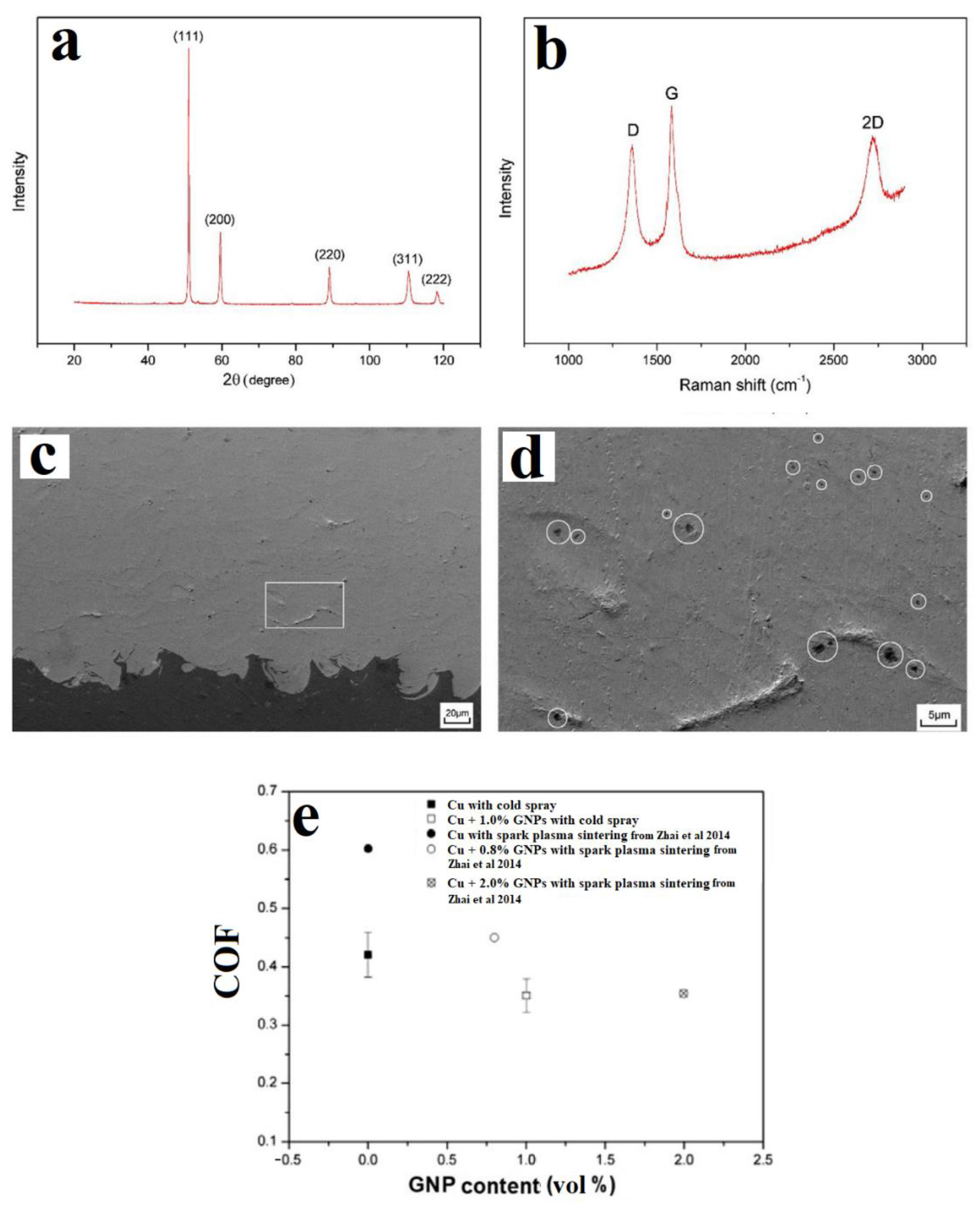
  49. Yin, S.; Zhang, Z.; Ekoi, E.J.; Wang, J.J.; Dowling, D.P.; Nicolosi, V.; Lupoi, R. Novel cold spray for fabricating graphene-reinforced metal matrix composites. Mater. Lett. 2017, 196, 172–175. [Google Scholar] [CrossRef]
  50. Kaniyoor, A.; Ramaprabhu, S. A Raman spectroscopic investigation of graphite oxide derived graphene. AIP Adv. 2012, 2, 032183. [Google Scholar] [CrossRef] [Green Version]
  51. Perumbilavil, S.; Sankar, P.; Rose, T.P.; Philip, R. White light Z-scan measurements of ultrafast optical nonlinearity in reduced graphene oxide nanosheets in the 400–700 nm region. Appl. Phys. Lett. 2015, 107, 051104. [Google Scholar] [CrossRef]
  52. Zhai, W.; Shi, X.; Wang, M.; Xu, Z.; Yao, J.; Song, S.; Wang, Y. Grain refinement: A mechanism for graphene nanoplatelets to reduce friction and wear of Ni3Al matrix self-lubricating composites. Wear 2014, 310, 33–40. [Google Scholar] [CrossRef]
  53. Sun, W.; Tan, A.W.Y.; Bhowmik, A.; Xue, F.; Marinescu, I.; Liu, E. Evaluation of cold sprayed graphene nanoplates–Inconel 718 composite coatings. Surf. Coat. Technol. 2019, 378, 125065. [Google Scholar] [CrossRef]
  54. Zhao, Z.; Meng, F.; Tang, J.; Liu, H.; Liu, H.; Yang, L.; Wang, J.; Xiong, T. A novel method of fabricating an antibacterial aluminum-matrix composite coating doped graphene/silver-nanoparticle. Mater. Lett. 2019, 245, 211–214. [Google Scholar] [CrossRef]
  55. Liu, Y.; Dang, Z.; Wang, Y.; Huang, J.; Li, H. Hydroxyapatite/graphene-nanosheet composite coatings deposited by vacuum cold spraying for biomedical applications: Inherited nanostructures and enhanced properties. Carbon 2014, 67, 250–259. [Google Scholar] [CrossRef]
  56. Liu, Y.; Huang, J.; Li, H. Nanostructural Characteristics of Vacuum Cold-Sprayed Hydroxyapatite/Graphene-Nanosheet Coatings for Biomedical Applications. J. Therm. Spray Technol. 2014, 23, 1149–1156. [Google Scholar] [CrossRef]
  57. Samuel, E.; Lee, J.G.; Joshi, B.; Kim, T.G.; Kim, M.W.; Seong, I.W.; Yoon, W.Y.; Yoon, S.S. Supersonic cold spraying of titania nanoparticles on reduced graphene oxide for lithium ion battery anodes. J. Alloy. Compd. 2017, 715, 161–169. [Google Scholar] [CrossRef]
  58. Aldalbahi, A.; Edmund, S.; Alotaibi, B.S.; El-Hamshary, H.; Yoon, S.S. Reduced graphene oxide supersonically sprayed on wearable fabric and decorated with iron oxide for supercapacitor applications. J. Mater. Sci. Technol. 2021, 82, 47–56. [Google Scholar] [CrossRef]
  59. Lee, J.G.; Joshi, B.N.; Lee, J.H.; Kim, T.G.; Kim, D.Y.; Al-Deyab, S.S.; Seong, I.W.; Swihart, M.T.; Yoon, W.Y.; Yoon, S.S. Stable High-Capacity Lithium Ion Battery Anodes Produced by Supersonic Spray Deposition of Hematite Nanoparticles and Self-Healing Reduced Graphene Oxide. Electrochim. Acta 2017, 228, 604–610. [Google Scholar] [CrossRef]
  60. Samuel, E.; Kim, T.G.; Park, C.W.; Joshi, B.; Swihart, M.T.; Yoon, S.S. Supersonically Sprayed Zn2SnO4/SnO2/CNT Nanocomposites for High-Performance Supercapacitor Electrodes. ACS Sustain. Chem. Eng. 2019, 7, 14031–14040. [Google Scholar] [CrossRef]
  61. Joshi, B.; Lee, J.G.; Samuel, E.; Jo, H.S.; Kim, T.G.; Swihart, M.T.; Yoon, W.Y.; Yoon, S.S. Supersonically blown reduced graphene oxide loaded Fe–Fe3C nanofibers for lithium ion battery anodes. J. Alloy. Compd. 2017, 726, 114–120. [Google Scholar] [CrossRef]
  62. Samuel, E.; Joshi, B.; Park, C.; Aldalbahi, A.; Rahaman, M.; Yoon, S.S. Supersonically sprayed rGO/ZIF8 on nickel nanocone substrate for highly stable supercapacitor electrodes. Electrochim. Acta 2020, 362, 137154. [Google Scholar] [CrossRef]
  63. Zhang, L.; Hou, G.; Zhai, W.; Ai, Q.; Feng, J.; Zhang, L.; Si, P.; Ci, L. Aluminum/graphene composites with enhanced heat-dissipation properties by in-situ reduction of graphene oxide on aluminum particles. J. Alloy. Compd. 2018, 748, 854–860. [Google Scholar] [CrossRef]
  64. Teng, S.; Gao, Y.; Cao, F.; Kong, D.; Zheng, X.; Ma, X.; Zhi, L. Zinc-reduced graphene oxide for enhanced corrosion protection of zinc-rich epoxy coatings. Prog. Org. Coat. 2018, 123, 185–189. [Google Scholar] [CrossRef]
  65. Hidayah, N.M.S.; Liu, W.-W.; Lai, C.-W.; Noriman, N.Z.; Khe, C.-S.; Hashim, U.; Lee, H.C. Comparison on graphite, graphene oxide and reduced graphene oxide: Synthesis and characterization. AIP Conf. Proc. 2017, 1892, 150002. [Google Scholar]
  66. Tkachev, S.V.; Buslaeva, E.Y.; Naumkin, A.V.; Kotova, S.L.; Laure, I.V.; Gubin, S.P. Reduced graphene oxide. Inorg. Mater. 2012, 48, 796–802. [Google Scholar] [CrossRef]
  67. Wu, H.; Zhang, L.; Liu, C.; Mai, Y.; Zhang, Y.; Jie, X. Deposition of Zn-G/Al composite coating with excellent cathodic protection on low-carbon steel by low-pressure cold spraying. J. Alloy. Compd. 2020, 821, 153483. [Google Scholar] [CrossRef]
  68. Zhang, L.; Wang, X.; Wu, H.; Mai, Y.; Liu, C.; Jie, X. High densification and anti-corrosion of graphene-coated aluminum coating deposited on AZ31B magnesium by low-pressure cold spray. Carbon Lett. 2020, 30, 581–584. [Google Scholar] [CrossRef]
  69. Wu, H.; Shen, G.; Li, R.; Zhang, L.; Jie, X.; Liu, G. Influence of embedded reduced graphene oxide on the corrosion-wear performance of cold sprayed Zn-rGO/Al coating in NaCl solution. Surf. Coat. Technol. 2022, 429, 127856. [Google Scholar] [CrossRef]
  70. Wu, H.; Zhang, Y.; Long, S.; Zhang, L.; Jie, X. Tribological behavior of graphene anchored Mg-Al layered double hydroxide film on Mg alloy pre-sprayed Al coating. Appl. Surf. Sci. 2020, 530, 146536. [Google Scholar] [CrossRef]
  71. Wang, X.; Zhang, L.; Zhou, X.; Wu, W.; Jie, X. Corrosion behavior of Al2O3-reinforced graphene encapsulated Al composite coating fabricated by low pressure cold spraying. Surf. Coat. Technol. 2020, 386, 125486. [Google Scholar] [CrossRef]
  72. Wu, H.; Zhang, L.; Zhang, Y.; Long, S.; Jie, X. Corrosion behavior of Mg–Al LDH film in-situ assembled with graphene on Mg alloy pre-sprayed Al layer. J. Alloy. Compd. 2020, 834, 155107. [Google Scholar] [CrossRef]
  73. Prasad, K.; Nikzad, M.; Sbarski, I. Modeling Permeability in Multi-Phase Polymer Composites: A Critical Review of Semi-Empirical Approaches. Polym. Rev. 2021, 61, 194–237. [Google Scholar] [CrossRef]
  74. Kim, T.G.; Park, C.W.; Woo, D.Y.; Choi, J.; Yoon, S.S. Efficient heat spreader using supersonically sprayed graphene and silver nanowire. Appl. Therm. Eng. 2020, 165, 114572. [Google Scholar] [CrossRef]
  75. An, S.; Kim, D.-Y.; Lee, J.-G.; Jo, H.S.; Kim, M.-W.; Al-Deyab, S.S.; Choi, J.; Yoon, S.S. Supersonically sprayed reduced graphene oxide film to enhance critical heat flux in pool boiling. Int. J. Heat Mass Transf. 2016, 98, 124–130. [Google Scholar] [CrossRef]
  76. Choi, J.; Okimura, N.; Yamada, T.; Hirata, Y.; Ohtake, N.; Akasaka, H. Deposition of graphene–copper composite film by cold spray from particles with graphene grown on copper particles. Diam. Relat. Mater. 2021, 116, 108384. [Google Scholar] [CrossRef]
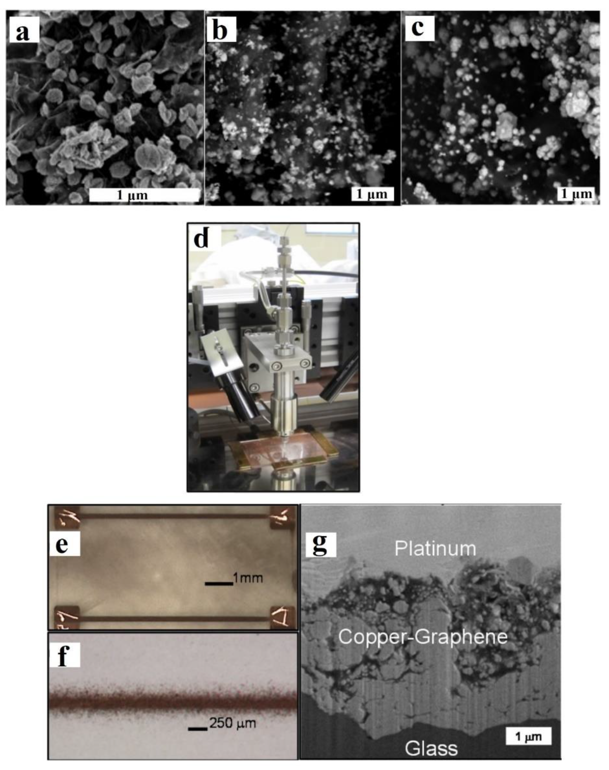
  77. Dardona, S.; Hoey, J.; She, Y.; Schmidt, W.R. Direct write of copper-graphene composite using micro-cold spray. AIP Adv. 2016, 6, 085013. [Google Scholar] [CrossRef]
Figure 1. (a) A typical CS machine consisting of a powder delivery nozzle, a movable robot arm, and a substrate on which deposition is carried out; (b) schematic representation of the typical cold spray process. Presented with permission from [27,33].
Carbon 08 00065 g001
Figure 2. Analysis of milled Cu (1 vol.%)/GNP feedstock: (a) XRD and (b) Raman spectra. (c) SEM image of the CS Cu/GNP coating exhibiting good coating characteristics, (d) high-magnification SEM image showing good inter-particle bonding between Cu and GNP phases, and (e) coefficient of friction (COF) of the coatings. Presented with permission from [49] benchmarked with data from Zhai et al. [52].
Carbon 08 00065 g002
Figure 3. (a) XRD patterns and (b) Raman spectra of the raw materials and the milled and sprayed IN718 GNP composites, surface topologies of CS coatings with different GNP loadings (in wt%): (c) 0%, (d) 0.15%, (e) 0.3%, (f) 1%. (g) DE of the IN718/GNP composite coatings. Presented with permission from [53].
Carbon 08 00065 g003
Figure 4. (a) Raman spectra; (b) XRD patterns of raw GO powders; RGO/Ag composite powders (~80% RGO/20 Ag) and Al/RGO/Ag composite coating (1 wt% RGO/Ag powder); (c) cross-sectional SEM of the substrate, resin and coating; (d) magnified SEM images of the CS coating (e); (f) magnified SEM images of the Al/RGO/Ag composite coating with yellow arrows indicating the presence of Ag nanoparticles. Zones of inhibition against E. coli: (g) Control, (h) Al/RGO/Ag composite coating. Presented with permission from [54].
Carbon 08 00065 g004
Figure 5. (a) XRD patterns of pure Al and GNP/Al powders, (b) Raman spectrum of GNP/Al powder, (c) Raman spectrum of Zn/0.2% GNP/Al CS coating, (d) SEM of GNP/Al powder, (e) SEM image of Zn/Al CS coating, (f) SEM image of Zn/0.2% GNP/Al CS coating. Presented with permission from [67].
Carbon 08 00065 g005
Figure 6. (a) SEM image of GNP/Al powder (0.75 wt% GNP), (b) Raman spectra of pure Al, raw GO, and RGO/Al powder, (c) SEM image of CS pure Al coating, (d) SEM image of CS GNP/Al composite coating, (e) corrosion behaviour (open-circuit potential) and images of corroded pure Al and GNP/Al composite coatings. Presented with permission from [68].
Carbon 08 00065 g006
Figure 7. (a): SEM image of CS Zn/RGO/Al composite coating showing embedding of the RGO within the coating, (b) microhardness trends with varying RGO content, (c) average COF of the CS composite coatings in air, and (d) average COF of the CS composite coatings in NaCl. Presented with permission from [69].
Carbon 08 00065 g007
Figure 8. (a) Raman spectra of pure Al, GO, and RGO coated on Al pre-CS, (b) SEM image of pure Al CS coating, (c) SEM image of GNP/Al CS coating, (d) SEM image of LDH (Layered Double Hydroxide) CS coating, (e) SEM image of GNP/LDH CS coating, (f) COF (coefficient of friction), and (g) wear rate. Presented with permission from [70].
Carbon 08 00065 g008
Figure 9. (a): Schematic of GO in situ reduction and CS, (b) Raman spectra, (c) mechanism of corrosion in pure Al coating, and (d) mechanism of corrosion in GNP/Al composite coating. Presented with permission from [71].
Carbon 08 00065 g009
Figure 10. (a,b) Heat spreader comprising multiple layers of RGO and AgNWs, IR images of (c) bare heat spreader, (d) RGO heat spreader, (e) hybrid RGO/AgNW heat spreader, (f) conductive (R1) and convective (R2) component values for the bare, RGO coating and RGO/AgNW hybrid heat spreaders. Presented with permission from [74].
Carbon 08 00065 g010
Figure 11. (a) Raman spectra of pristine RGO powder and RGO film, (b) effective heat transfer coefficient vs. heat flux of the RGO film and the bare copper plate, (c) schematic of pool boiling on CS RGO film surface. Presented with permission from [75].
Carbon 08 00065 g011
Figure 12. (a) CS Cu film, (b) CS Cu/G (0.019 wt% G) composite film, (c) friction coefficient of Cu and Cu/G composite films and wear tracks of the BoD ball on (d), (f) Cu film, and (e,g) Cu-G composite film. Presented with permission from [76].
Carbon 08 00065 g012
Figure 13. SEM micrographs of electroless plated Cu/GNP for (a) 1.5 h, (b) 3 h, and (c) 4.5 h; (d) image of micro-CS deposition head; (e,f) optical images of micro-CS-printed Cu//GNPs on frosted glass slide; and (g) FIB cross section of micro-CS Cu//GNPs showing GNP-rich areas (near the top) and Cu-rich areas (near the glass substrate). Presented with permission from [77].
Carbon 08 00065 g013
Figure 14. Schematic representing the three research areas to develop metal/GNP cold-sprayed parts.
Carbon 08 00065 g014
Table 1. Electrochemical resistance of Zn/Al and Zn/GNP/Al CS coatings. Rct is the mean charge transfer resistance at the coat/solution interface in parallel with the double-layer constant phase, Rs is the solution resistance; and Rfilm is the resistance of the coating in parallel with a constant phase element. The sum of Rfilm and Rct is used to characterise corrosion resistance. Presented with permission from [67].
SampleRSRfilmRctRfilm + Rct
Zn/Al5.387163.054701215.6
Zn/0.1% GNP/Al8.46192.29485.1494.32
Zn/0.2% GNP/Al2.891183.7184.7
Zn/0.3% GNP/Al4.3191.868538539.868
Table 2. Resistivity measurements of 4 micro-CS-printed Cu//GNP lines. Presented with permission from [77].
SampleResistance (Ω)Cross-Sectional Area (m2)Resistivity (Ω-m)Bulk Resistivity (Ω-m)
Line 133.13.28 × 10−101.09 × 10−665
Line 228.85.65 × 10−101.63 × 10−696.9
Line 351.44.88 × 10−102.51 × 10−6149
Line 439.24.90 × 10−101.92 × 10−6114
Publisher’s Note: MDPI stays neutral with regard to jurisdictional claims in published maps and institutional affiliations.

