Article

Effect of Molybdenum Content on Mechanical and Tribological Properties of Diamond-Like Carbon Coatings over Titanium β-21S Alloy

by
Dilli Babu Padmanaban
1,2,
Loganathan Mohan
1,3,
Preetam Giri
1,
Parthasarathi Bera
1,*,
Chinnasamy Anandan
1,* and
Harish C. Barshilia
1
1
Surface Engineering Division, CSIR–National Aerospace Laboratories, Bengaluru 560017, India
2
School of Engineering, Ulster University-Jordanstown, Belfast BT37 0QB, UK
3
Department of Mechanical Engineering, Toyohashi University of Technology, Toyohashi, Aichi 441-8580, Japan
*
Authors to whom correspondence should be addressed.
Submission received: 6 November 2020 / Revised: 13 December 2020 / Accepted: 16 December 2020 / Published: 22 December 2020
(This article belongs to the Special Issue Carbon-Based Composites for Energy and Biomedical Applications)

Abstract

:
Molybdenum-doped diamond-like carbon (Mo-DLC) coatings have been deposited on titanium β-21S alloy (Ti–15Mo–3Nb–3Al–0.2Si) using plasma-enhanced chemical vapor deposition (PECVD) equipped with pulsed-DC magnetron sputtering. Mo contents in the deposited coatings have been controlled with an applied sputtering pulse duty cycle. Chemical composition, structure, morphology, and topography have been studied using X-ray photoelectron spectroscopy (XPS), X-ray diffraction (XRD), field emission scanning electron microscopy (FESEM), and atomic force microscopy (AFM), respectively. XRD pattern of the coating with highest Mo content shows the presence of carbide phase. Smooth features with low roughness values are observed in low Mo content coating, whereas high Mo content coating shows granular characteristics with a high roughness value. Raman spectra reveal the increased graphitic content for the highest metal concentration in the coatings, wherein the nanohardness is also determined to be highest, at about ~18–19 GPa. Furthermore, the ball-on-disk tribometry test on Mo-DLC coating with highest nanohardness shows a low coefficient of friction (COF) of 0.2 with low wear loss compared to that of the substrate (0.62).

Graphical Abstract

1. Introduction

Diamond-like carbon (DLC) coatings have widespread industrial applications for their low friction coefficient [1,2,3,4], corrosion-resistance [5,6,7], biocompatibility [8], high hardness [9], chemical inertness [10,11,12,13,14,15], surface functionality [16], etc. However, the coatings suffer failures on substrates, mostly due to intrinsic stress [17]. It has been observed that incorporating metal interlayer or metal doping in a carbon matrix significantly improved the coating stability on various substrates [18,19]. In this sense, transition metal-doped diamond-like carbon (M-DLC) coatings have attracted great attention in recent decades for their excellent tribo-mechanical properties. Cu, Ag, Fe, Ti, Cr, W, etc. are some of the metals used as dopants in carbon matrix to enhance the property of the coatings [20,21,22,23,24,25,26]. M-DLC coatings can be tuned with controlled metal inclusion, from a diamond- to a graphite-like nature, which can be used as dry lubrication agents. Metal doping is also likely to induce metallic or carbide nanoclusters that brings good thermal stability [27], superior wear resistance [28], high electrical conductivity [29], good adhesion [30], enhanced optical property [31], better magnetic behavior [32], etc.
Titanium alloys are excellent materials for biomedical research and they have widely been considered as bioimplants for their lightweight, corrosion-resistant, high strength, low modulus properties [33,34,35,36,37,38,39]. Among various phases of titanium alloys, β class-containing elements such as Mo, Sn, Ta, Nb, and Zr [40] are preferred for orthopedic implants because of their non-toxic nature and superior properties [41,42]. Particularly, the β class of Ti-Mo alloys have extensively been reported as biomaterials for their superior mechanical and corrosion properties [42,43,44,45,46,47]. However, titanium alloys have some limitations because of their poor tribological performance, high coefficients of friction, and the absence of mechanical stability due to formation of their native oxides. In this regard, surface modification of titanium alloys is a well-known process to improve their mechanical and tribological properties [48,49]. Surface modification with biocompatible DLC coating is one of the practicable routes for enhanced mechanical and tribological properties of titanium alloys [49].
In this research work, we have investigated the mechanical and tribological behaviors of surface-modified titanium β-21S alloys (Ti–15Mo–3Nb–3Al–0.2Si) using molybdenum-doped DLC coatings. In general, pure DLC and M-DLC coatings are commonly deposited using chemical vapor deposition (CVD) and physical vapour deposition (PVD) methods [50,51,52,53,54,55,56,57]. These coatings are also reported to be deposited on titanium and its alloys to improve their overall properties [58,59,60]. Molybdenum is a common transition metal found to exist in several oxidation states. It readily forms thermally stable alloys and hard carbides [61] and shows enhanced blood compatible [62] and biocompatible [63] properties. The present work has been motivated by these characteristics of Mo metal. Some of the earlier reports on Mo-doped DLC coatings have demonstrated their improved thermal, mechanical, tribological, and biocompatible properties [6,51,64,65,66,67]. However, development of Mo-DLC coatings on the titanium β-21S alloy is limited in the literature [6]. Here, we present the deposition of Mo-DLC coatings on titanium β-21S alloys using plasma-enhanced chemical vapor deposition (PECVD). Deposition of Mo-DLC coatings has been carried out using methane (CH4) as the precursor gas for DLC coating with simultaneous Mo incorporation by magnetron sputtering, employing aMo target. The study includes a variation of Mo content through magnetron sputtering along with chemical vapor deposition of carbon matrix in the coatings. We have extensively studied the properties of the coatings toward tribological application.

2. Materials and Methods

2.1. Substrate Preparation

Titanium β-21S alloy (Ti–15Mo–3Nb–3Al–0.2Si) with a size of 2 cm × 2 cm, and Si(100) wafers with a size of 1 cm × 1 cm, were mainly used as the substrate materials for this study. The surface of each titanium alloy substrate, hereafter called Ti-Mo, was ground and polished to a mirror finish in order to remove any unwanted contamination and/or oxide layers. The Si wafer and polished Ti-Mo substrates were then separately ultrasonically cleaned for 15 min in acetone, dried, and loaded together into deposition chamber of PECVD system.

2.2. Deposition

Figure 1 shows the entire set up of the PECVD system used for this research. Before deposition of coatings, the chamber was evacuated to a base pressure of 5 × 10⁻⁶ mbar through turbo-molecular pump backed with an oil rotary pump. At first, inductively coupled Ar plasma was created by 50 W RF power at 13.56 MHz frequency to clean the substrates for about 10 min at a bias of −200 V. The process was continued with deposition of coatings by introducing CH4 gas with Ar in a mixing ratio of 3:7. At the same time, Mo was sputtered from a 99.9% pure Mo target with a 3 inch diameter through a magnetron gun powered by a symmetric bipolar-pulsed DC power supply from MAGPULS Stromversorgungs Systeme GmbH, Germany. During the deposition, the chamber pressure was maintained at 11 μbar. The substrates were negatively biased with −150 V. Keeping all the process conditions sputtering bias to 300 V and frequency at 10 kHz as the same, Mo content in the coatings were varied through the bipolar pulse on-time and off-time such that the duty cycles are fixed to 10%, 40%, and 85%, where duty cycle = positive pulse on-time/ (total pulse duration). Generally, all the experiments were conducted for a duration of 30 min. However, for wear testing, samples were prepared for 60 min with a pulse duty cycle of 40%.

2.3. Characterization

The chemical compositions and nature elemental species of Mo-DLC coatings were analyzed by X-ray photoelectron spectroscopy (XPS) using an SPECS spectrometer (SPECS Surface Nano Analysis GmbH, Berlin, Germany). Spectra were recorded using non-monochromatic AlKα radiation (1486.6 eV) as an X-ray source operated at 150 W (12 kV, 12.5 mA). The binding energies reported here were referenced with C 1s peak at 284.6 eV. Survey spectra were obtained with pass energy of 70 eV and a step increment of 0.5 eV. All the individual core level spectra of C 1s and Mo 3d were recorded with a pass energy and step increment of 25 and 0.05 eV, respectively. For XPS recording, a coating sample was mounted on the sample holder and placed into a load-lock chamber with an ultrahigh vacuum (UHV) of 8 × 10⁻⁸ mbar for 5 h in order to desorb any volatile species present on its surface. After 5 h, the sample was transferred into the analyzing chamber with UHV of 5 × 10⁻¹⁰ mbar and spectra were recorded. The atomic percentages of Mo in the Mo-DLC coatings were estimated using the areas under the Mo 3d and C 1s core level peaks and the respective XPS relative sensitivity factors (RSF). C 1s and Mo 3d core level spectra were also curve-fitted with Gaussian–Lorentzian peaks to identify various carbon and molybdenum species after Shirley background subtraction. Relative concentrations of different carbon and molybdenum species were evaluated from the area under the respective peak in the curve-fitted spectrum.
XRD patterns of Si substrate and Mo-DLC coatings on the substrate with high and low Mo contents were recorded, employing an X-ray diffractometer (Bruker D8 advance) operated with CuKα radiation (λ = 1.5406 Å) at 35 kV and 10 mA. The samples were scanned over 2θ range of 30–55°.
Surface morphologies of the coatings on Si substrate were obtained by FESEM with Carl Zeiss SUPRA 40VP.
Surface topography was investigated by AFM with Surface Imaging Systems on a 10 µm × 10 µm area on the coatings on Si substrate (CSEM Instruments (Model SSI)) operated in contact mode.
Raman spectra were collected using confocal micro Raman spectrometer with DILOR-JOBIN-YVON SPEX (LABRAM 010A) and a He-Ne laser source at a wavelength of 632.8 nm. Raman spectra were also obtained on the wear tracks of Mo-DLC coatings to understand the change in materials during the friction process.
Optical micrographs of wear tracks of Mo-DLC coatings and substrate were collected using an Olympus microscope to find out the nature of wear that occurred on the coatings and the substrate.

2.4. Properties

Nanohardnesses of the Mo-DLC coatings were tested using a Nano Hardness Tester (CSM Instruments, Peseux, Switzerland) with a Berkovich diamond indenter at a 5 mN load. The values were determined from the indentation curves using the Oliver and Pharr method [68].
Wear studies of bare substrate and Mo-DLC-coated substrate were carried out in a reciprocating wear tester (model CM 9084 DuCom) as per ASTM G133-02 standard [37]. However, these tests are not in full compliance with the provisions of Test Method G 133, Procedure A, because the normal forces in these experiments were 3 and 5 N instead of 25 N as prescribed by the standard. Moreover, the stroke length was 10 mm and an alumina ball of 6 mm diameter was used as the counter surface. Furthermore, the experiments were carried out at a frequency of 100 Hz min−1 for 20 min. Relative humidity during tribology measurements was around 65%. After the experiments, wear profiles of the samples were examined by a 3D-profilometer with Nanomap 500 LS (AEP Technology, Santa Clara, CA, USA). Considering the ASTM G133-02 method, the wear losses were calculated from the cross-sectional areas of the respective wear profiles.

3. Results and Discussion

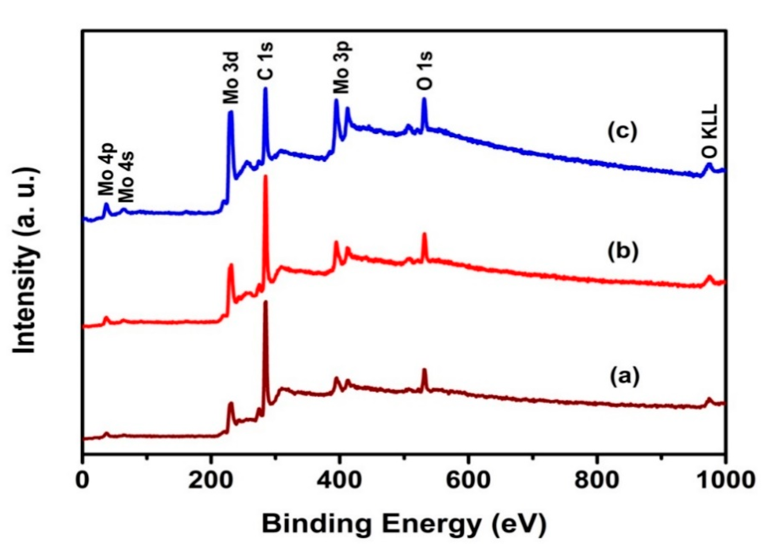
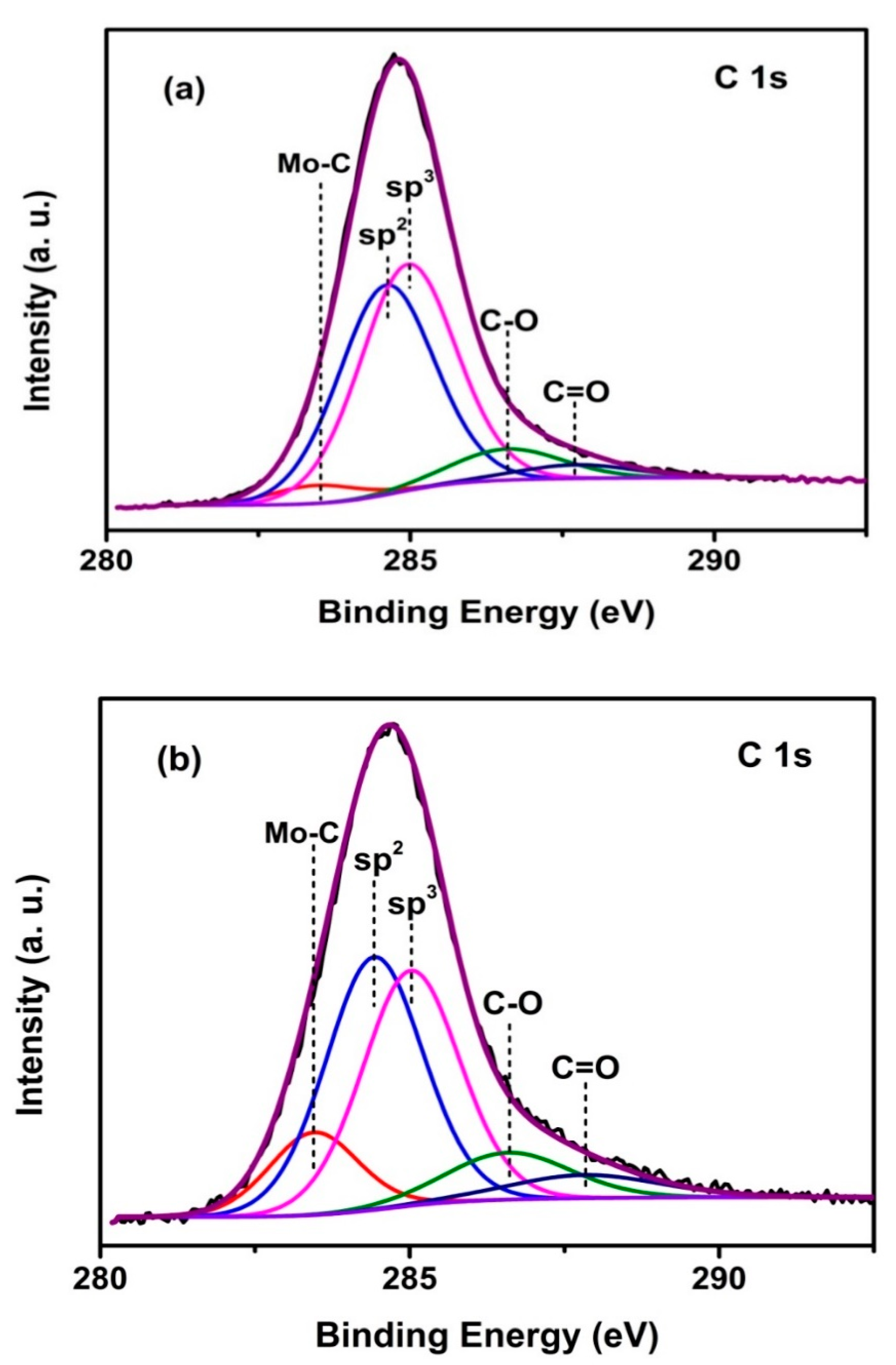
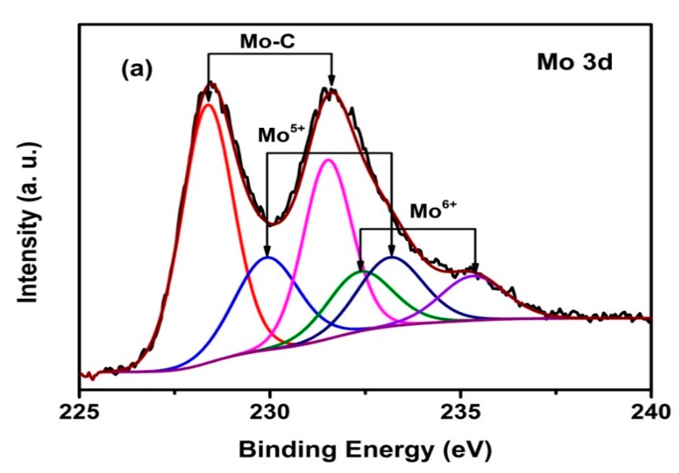
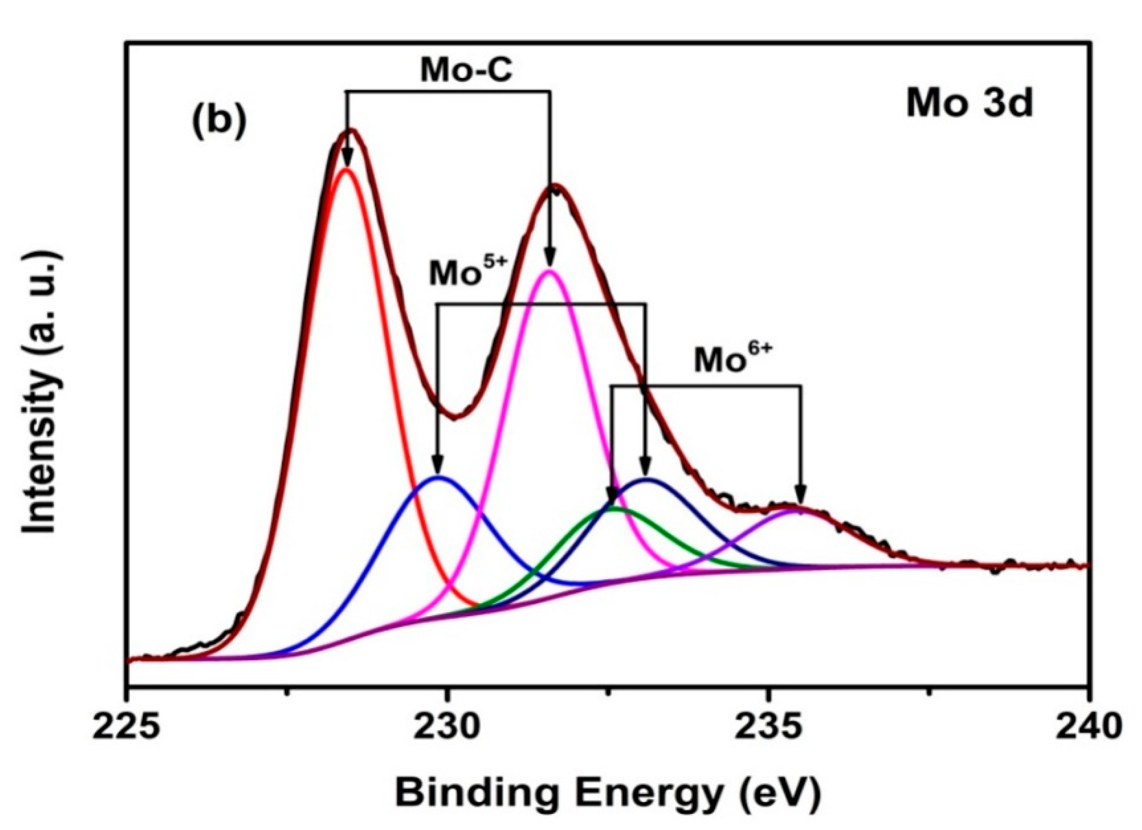
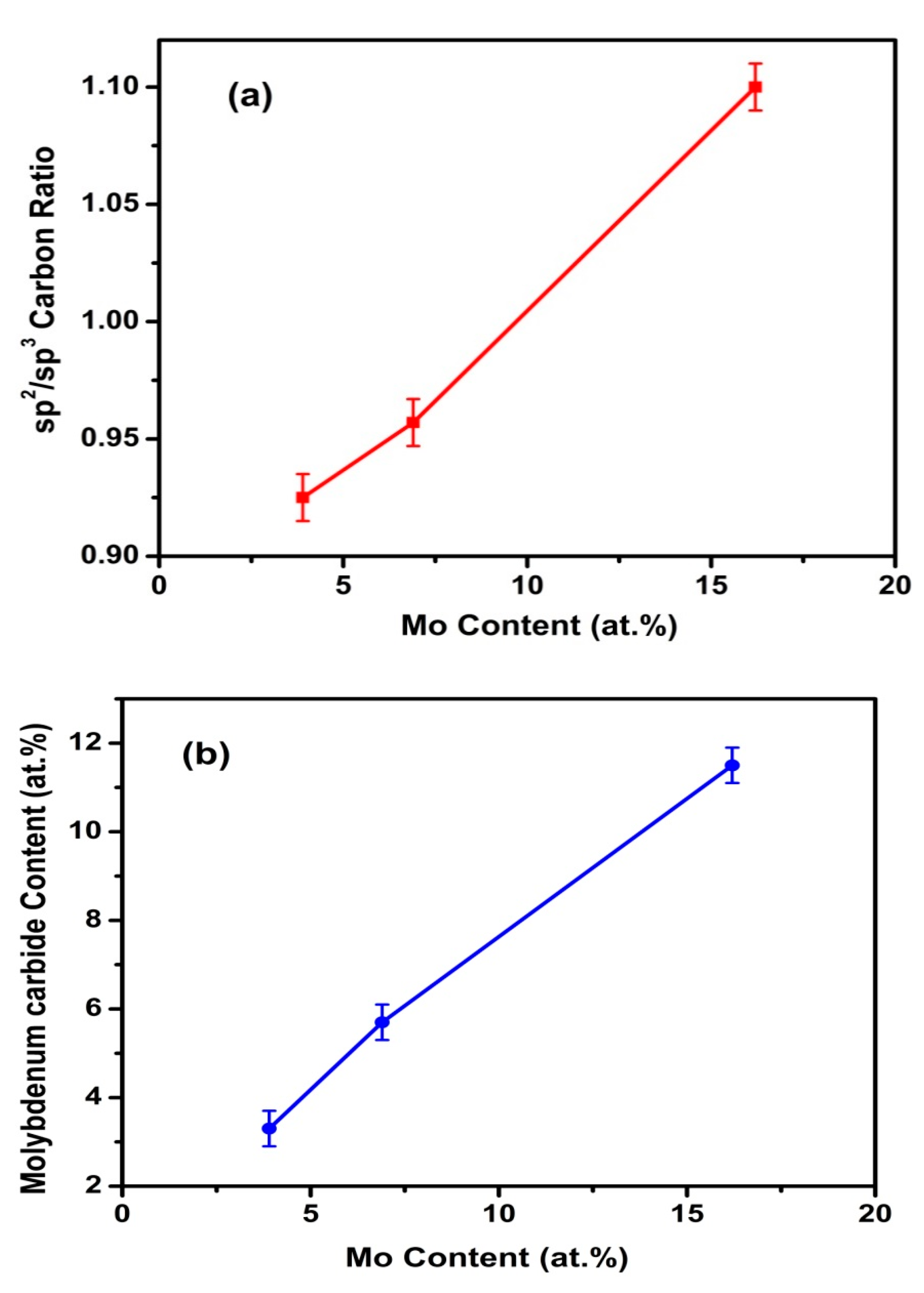
3.1. XPS Studies and Compositions
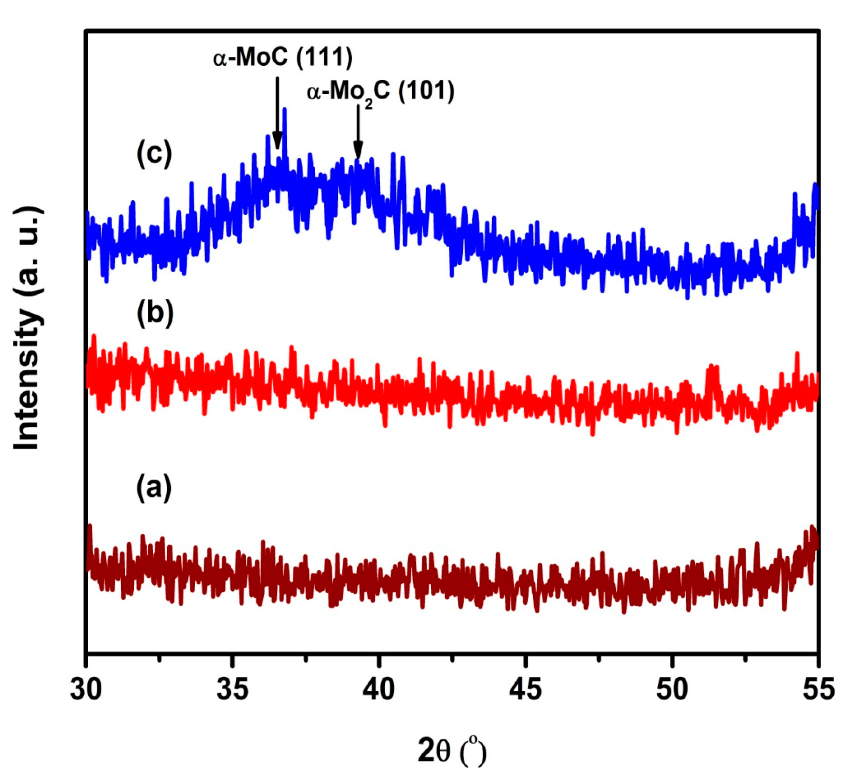
The nature of chemical bonds present in the coatings prepared with different duty cycles and their compositions have been identified using XPS. Survey spectra of Mo-DLC coatings in Figure 2 reveal the peaks related to C 1s, Mo 3d, and O 1s. These peaks confirm the presence of molybdenum and carbon in the coatings. The presence of oxygen could arise because of exposure of coatings to atmosphere prior to XPS measurements. The atomic percentages of Mo in Mo-DLC coatings evaluated from their core level spectra are 3.9%, 6.9%, and 16.2%, respectively. As high-resolution C 1s core level spectra are found to be asymmetric in nature, an in-depth chemical analysis has been carried out to decompose the spectra into various carbon component species using non-linear curve-fitting. Figure 3 presents curve-fitted C 1s core level spectra of Mo-DLC coatings. The component peaks at 284.6 and 285.0 eV are identified to be sp2 hybridized carbon (C=C) and sp3 hybridized carbon (C–C) [69], whereas the peak at lower binding energy of 283.5 eV is related to Mo–C bonds [51]. The peaks at 286.6 and 287.7 eV are attributed to C–O and C=O bonds, respectively [2,4]. The difference in binding energies between sp3 and sp2 carbons is associated with their coordination, hydridization, and core-hole relaxation [70]. Broad Mo 3d core level spectral envelopes indicate the presence of different Mo species in the coatings and are resolved into component peaks by curve-fitting as displayed in Figure 4. Mo 3d5/2,3/2 doublet at 228.4 and 231.5 eV is identified as a molybdenum carbide species containing Mo–C bond. Observed doublet peaks in the curve-fitted spectra at 229.9 and 233.2 eV are assigned for Mo4+ species. Doublet binding energies at 232.4 and 235.3 eV correspond to Mo6+ species in the coatings [6,51]. However, relative concentrations of molybdenum carbide, Mo4+ and Mo6+ species are estimated from areas under the curves in respective Mo 3d core level spectra and are found to be different in the coatings. Binding energies and relative concentrations of carbon and molybdenum species are summarized in Table 1. Overall Mo contents are found to increase with the increase in the pulse duty cycles according to the table. Further, the effect of metal content is also understood through its carbide content and disordered nature. Figure 5 shows the estimated molybdenum carbide contents and sp2 to sp3 carbon ratios for various amounts of molybdenum inclusion in the DLC coatings. It has been found that sp2 carbon concentration gets increased with increase in Mo concentration. Nevertheless, the increase in sp2/sp3 ratio is because of the Mo doping that can be attributed to the catalyst effect of Mo atoms on the formation of sp2 sites. As sp2 carbon has lower binding energy compared to sp3 carbon, it prefers to bond with Mo to form Mo carbide phase. It is clearly observed that molybdenum carbide was found to increase with the increase in molybdenum content in turn to the applied duty cycle. This is also found to influence the disordered nature where graphitic nature improves over the diamond-like behaviour of the coatings.

3.2. XRD Studies

Figure 6 shows the XRD patterns of Mo-DLC coatings on Si substrate for low (3.9 at.%) and high (16.2 at.%) Mo contents along with bare Si substrates for comparison. No well-defined diffraction peak is observed in the diffraction pattern of low Mo-content coating. However, the coating with high Mo doping shows a broad signature containing two less intense peaks in the range of 33° to 40°. The observation of these peaks is associated with the presence of multiple carbide phases. Observed peaks at 36.7° are related to (111) plane of nanocrystalline cubic α-MoC (JCPDS No. 65-0280) [71] and 39.2° corresponds to (101) the plane of hexagonal α-Mo2C (JCPDS No. 35-0787) [72]. Mo2C is known to be an extremely hard ceramic material which can help in improving thermal stability. Thus, the diffraction peaks confirm the presence of molybdenum carbide in the Mo-DLC coating with high Mo content. Nevertheless, this finding is also corroborated with XPS results, wherein the presence of molybdenum carbide is clearly observed with respect to C 1s and Mo 3d core level spectra.

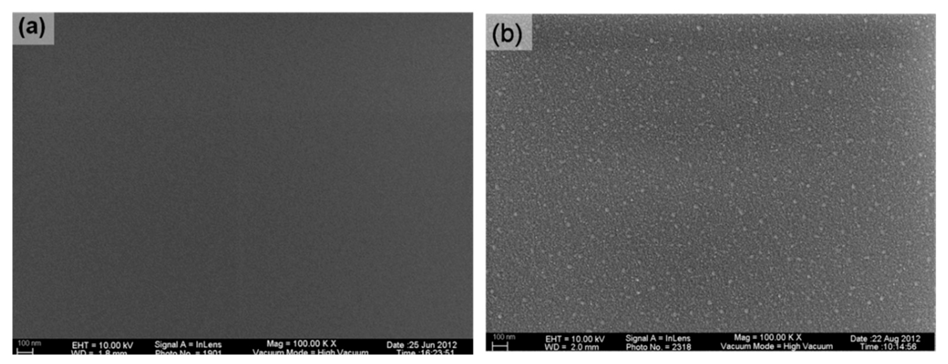
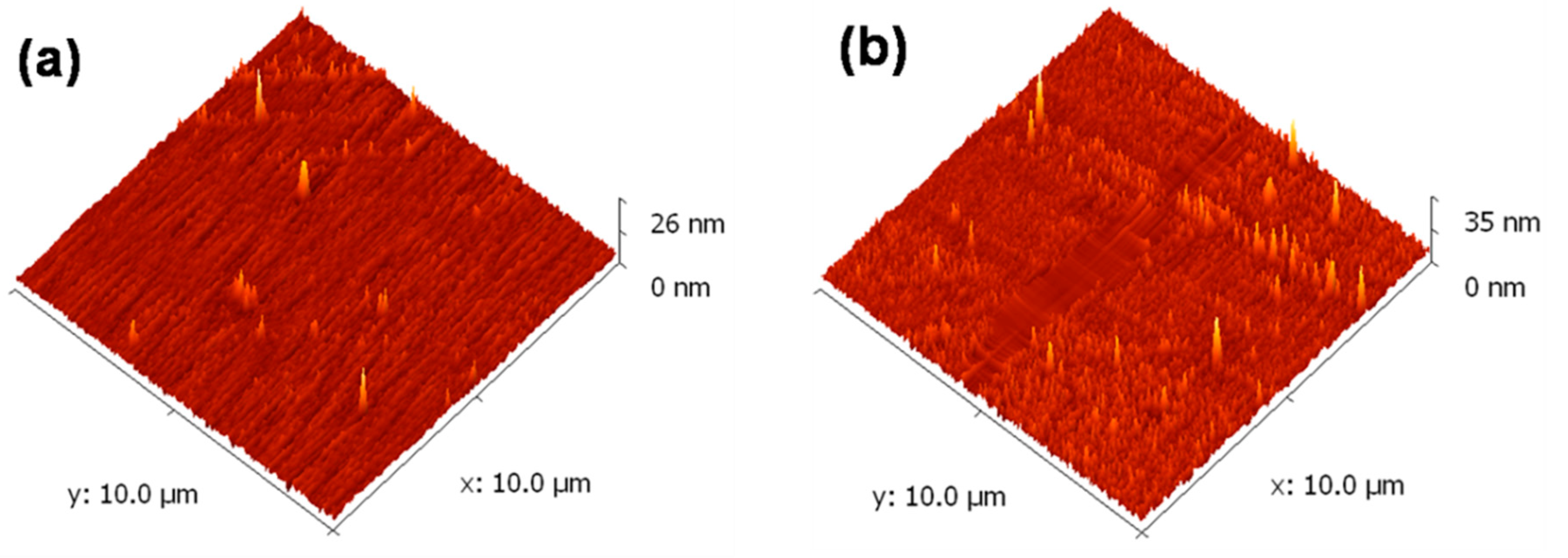
3.3. FESEM and AFM Studies

Surface morphology and topography, including surface roughness of Mo-DLC coatings for highest and lowest molybdenum content, are shown in Figure 7 and Figure 8, respectively. At 3.9 at.% Mo content, coating is found to be smooth, with corresponding surface roughness values of around 0.73 nm and appears as a highly smooth coating, as seen in Figure 7a. However, at higher Mo content of about 16.2 at.%, coating exhibits more granular features, possibly from the formation of nanoaggregate features with an increased roughness value of about 1.2 nm. This could be due to the presence of a higher fraction of molybdenum carbide phase and increased metallicity of the coating. Thus, scanning electron micrographs of the coatings corroborate the observation from atomic force microscopy as shown in Figure 8.

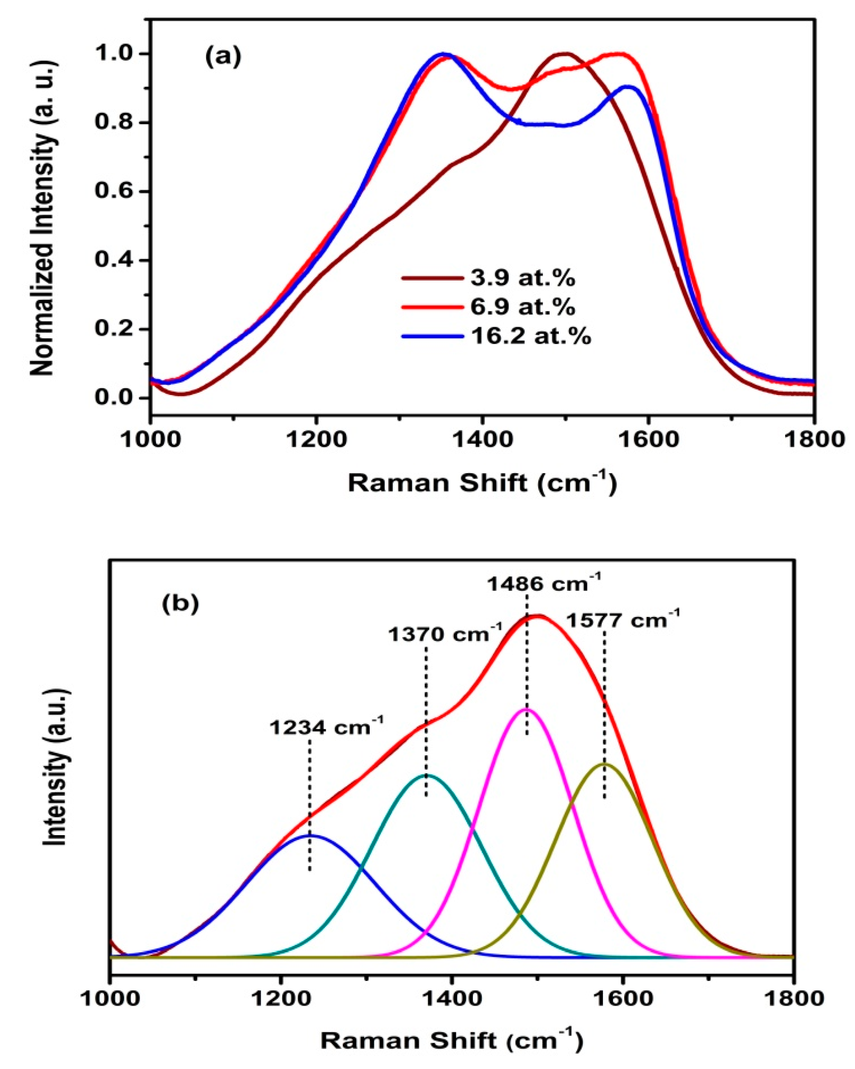
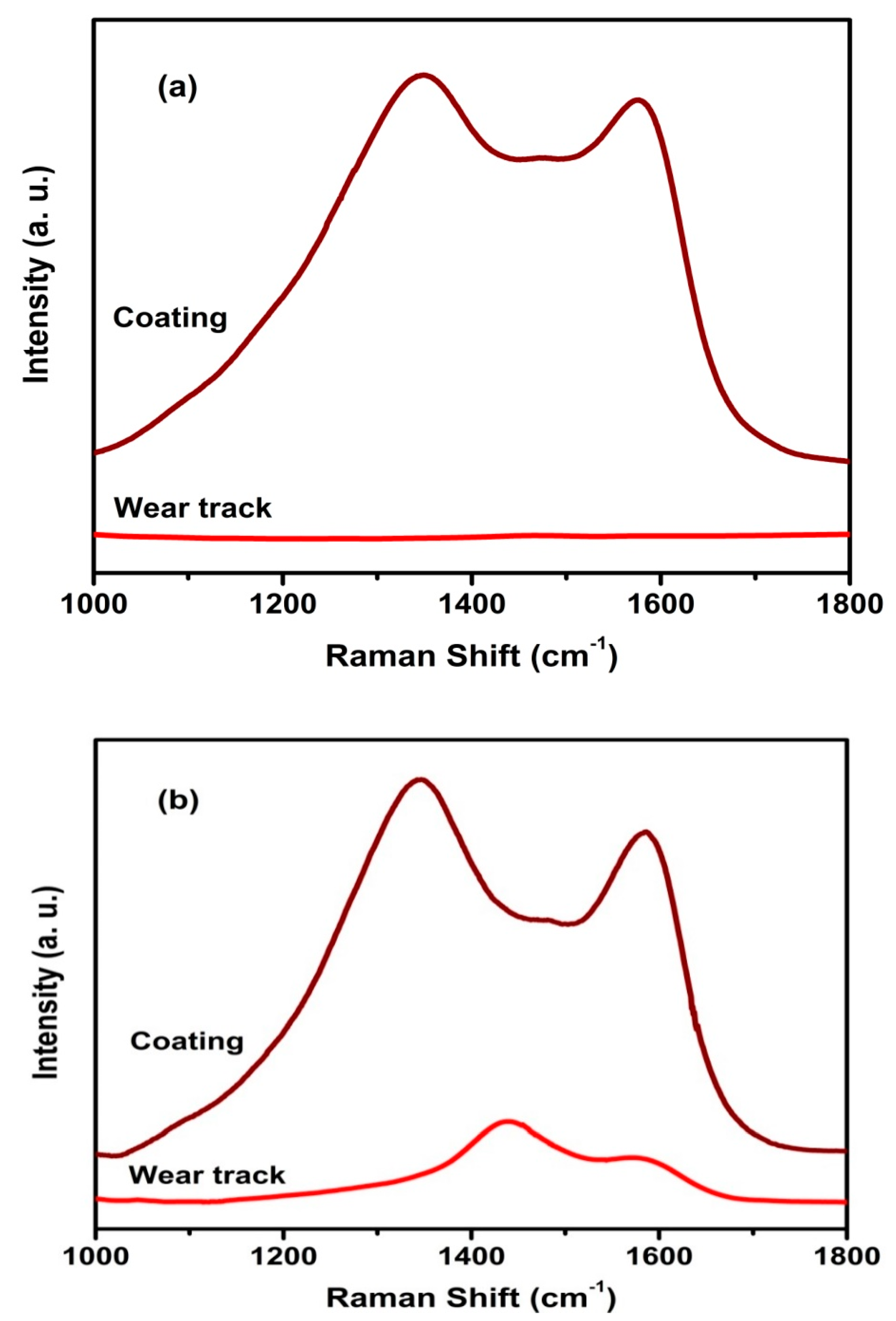
3.4. Raman Spectroscopy Studies

Structural and phase disorder of the coatings have been studied using micro Raman spectroscopy. Figure 9a shows typical Raman spectra of Mo-DLC coatings on Si substrate recorded in the range of 1000 to 1800 cm−1 for various Mo concentrations. The spectra provides information about the microstructural changes due to doping of Mo into the carbon matrix. As spectra are asymmetric, they are curve-fitted into several component peaks using a Gaussian function [73]. A typical curve-fitted Raman spectrum of 3.9 at.% Mo-DLC coating is presented in Figure 9b. The choice of using this function is because Gaussian line profile closely accounts to the nature and chemical disorder of bonds, whereas other fitting functions, such as Lorentzian functions, relate to the photoionization process [73]. Ferrari and Robertson have reported that Gaussian line function is resulted from random distribution of phonon lifetimes in disordered materials [74]. Therefore, the curve fitting using Gaussian function can provide a better insight into the coating. In the present study, all the spectra are curve-fitted into four components. G peak located around 1560–1580 cm−1 occurring due to E2g stretching of sp2 bonds in the ring as well as in chains and D peak at 1360 cm−1 is usually because of the disordered A1g breathing modes of sp2 carbon in the ring [75,76]. Along with these two peaks, two more peaks are found around 1200 cm−1 and 1480 cm−1 related to modes of trans polyacetylene, which are the sum and difference of C=C chain stretching and C–H wagging modes respectively [77]. It is to be noted that Raman spectrum indicate the ordering of sp2 sites and thereby measures the sp3 fraction in the coating.
The intensities of D and G peaks have been estimated from curve-fitted spectra for all three Mo-DLC coatings with different Mo concentrations. The intensity ratio (ID/IG) as a function of Mo content is presented Figure 9c. The ratio gives an insight into the amount of graphitization induced by Mo doping in the coatings. According to Chu et al., the ID/IG ratio represents the size of graphite plane in DLC coatings [78]. Tuinstra and Koenig have proposed that ID/IG is inversely related to the size of graphite cluster [79]. However, in the work of Cho and coworkers [80], when ID/IG value crosses over 1.1, this inverse relationship may no longer hold, and instead the ID/IG values behave proportional to graphitic content in the film. Therefore, in the case of Mo doping, the observed increase in ID/IG ratios from 0.94 to 1.3 can be associated to increased graphitization of the coating. In addition, full-width-at-half-maxima (FWHM) represent the measure of cluster size and structure disorder in the coatings. This occurs due to distortion in bond length and bond angle, particularly in sp2 sites [81,82]. Figure 9c reveals that FWHM of G peaks (FWHMG) decrease with Mo content in the coating. Thus, Mo incorporation induces increased sp2 clusters around the carbon matrix. As reported, increase in metal incorporation substantially reduces the residual stress, and in turn shows a decrease in FWHM of G peak and enhances its tribomechanical properties [83].
The observation on the sp2 clusters formation and ID/IG ratio can be substantiated with XPS analysis, wherein sp2 to sp3 C ratios are noted to increase with Mo contents. In short, as the sp2 to sp3 C decreases, the G peak intensity and ID/IG also decreases [84]. Many earlier works on M-DLC composite films have similarly been accounted for this type of linear behaviour [85]. Ji et al., in their Mo-DLC nanocomposite coating, have observed not only increased sp2 content with higher Mo doping, but also that Mo undergoes preferential bonding to sp2 carbon to form MoC [51]. A similar trend is also observed in the XPS analysis (Figure 5). Thus, these sp2 clusters in the Mo-DLC coatings mostly form chains and dimers undergo larger grain boundaries that lie around MoC [84,86].

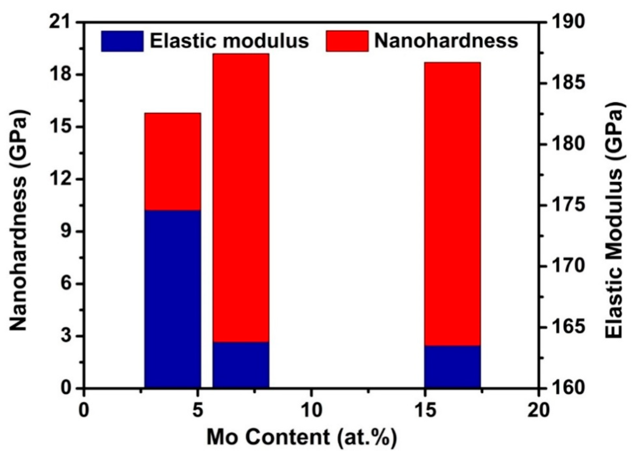
3.5. Mechanical Properties

Nanohardness and elastic modulus values of Mo-DLC coatings for various Mo contents are presented in Figure 10. The coatings show significant variation in nanohardness and elastic modulus values for various Mo contents. A high nanohardness of about 19.2 GPa was observed for the coating with 6.9 at.% Mo content, whereas the higher Mo content (16.2 at.%) coating shows a nanohardness value of 18.7 GPa. This slight variation in nanohardness with significant change in Mo content may possibly be due to variation in thickness of the coatings or distribution of MoC clusters in the carbon matrix. However, both the coatings (6.9 and 16.2 at.%) have same and lowest value of elastic modulus that can be corroborated with a saturated amount of MoC in the coatings as the Mo concentration increases. Thus, the consistency of nanohardness values across different places in the coating can be inferred from Figure 11, which shows series of nanoindentation curves obtained for the highest Mo content (16.2 at.%) coating.

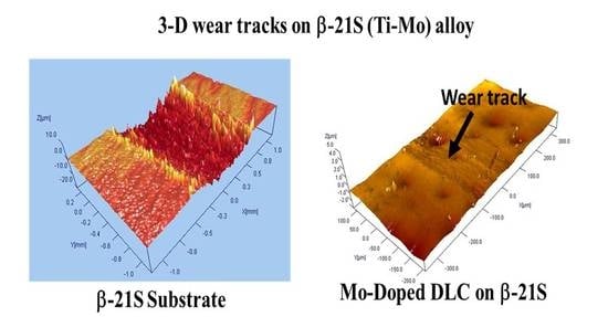
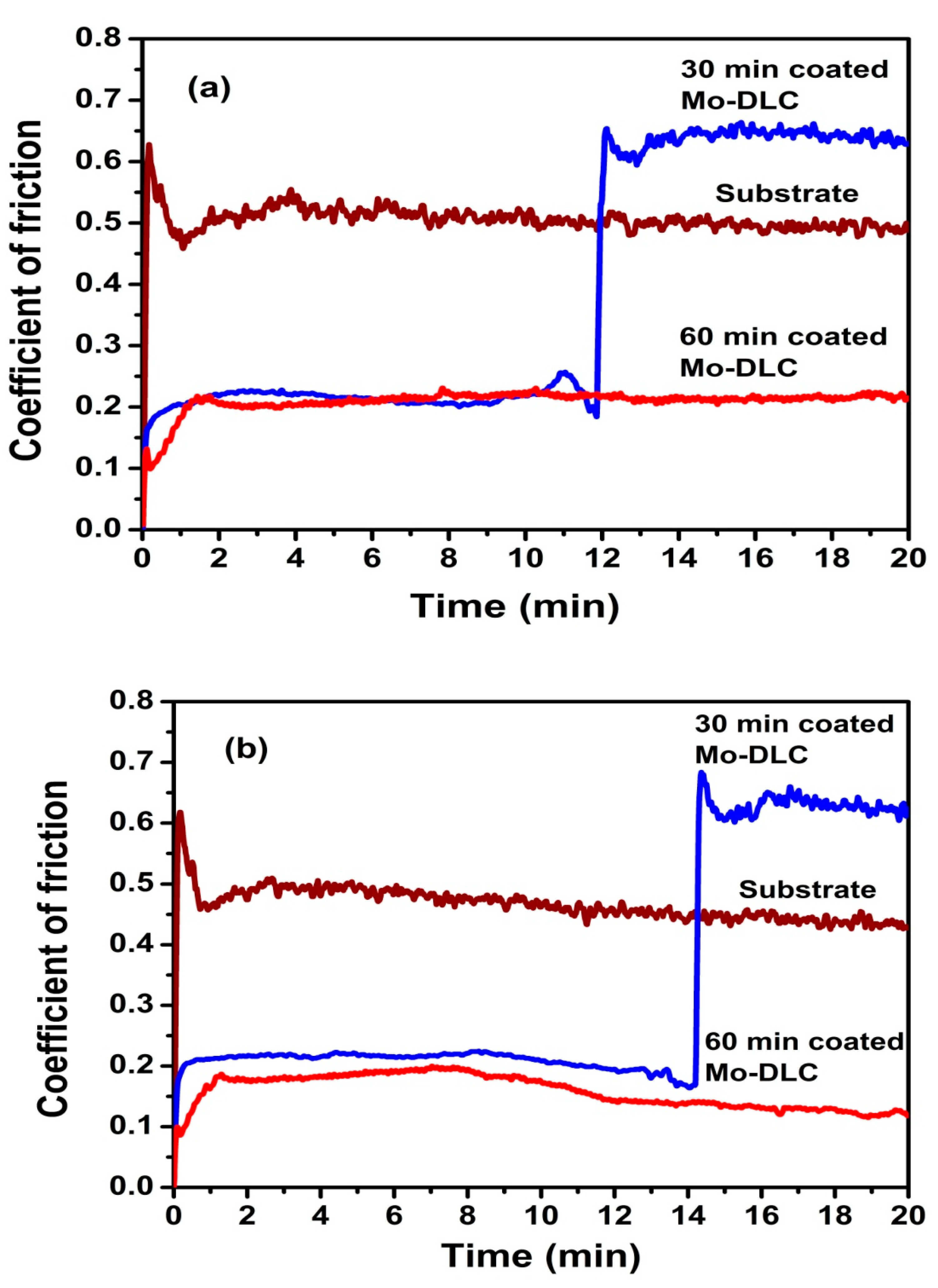
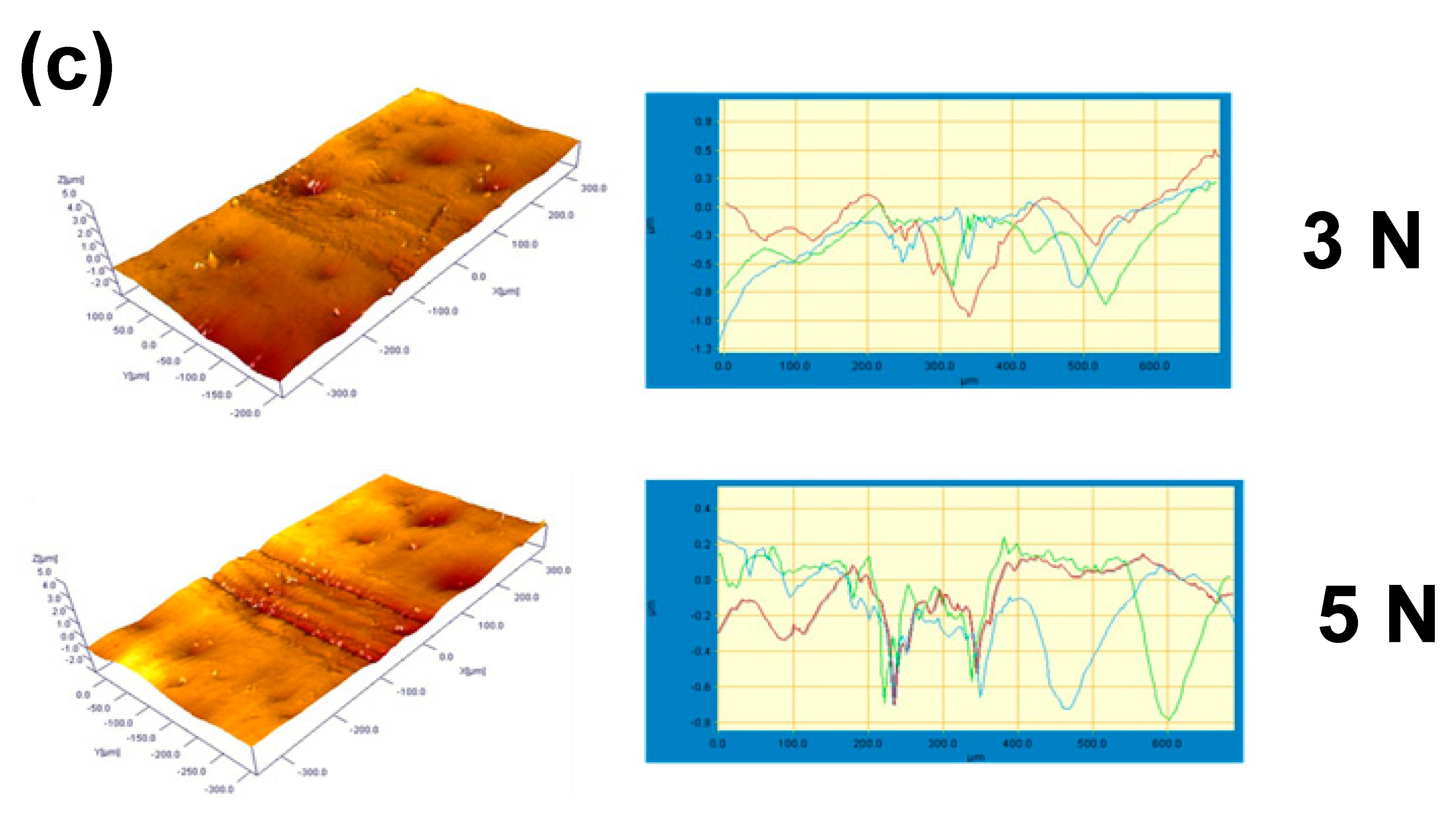
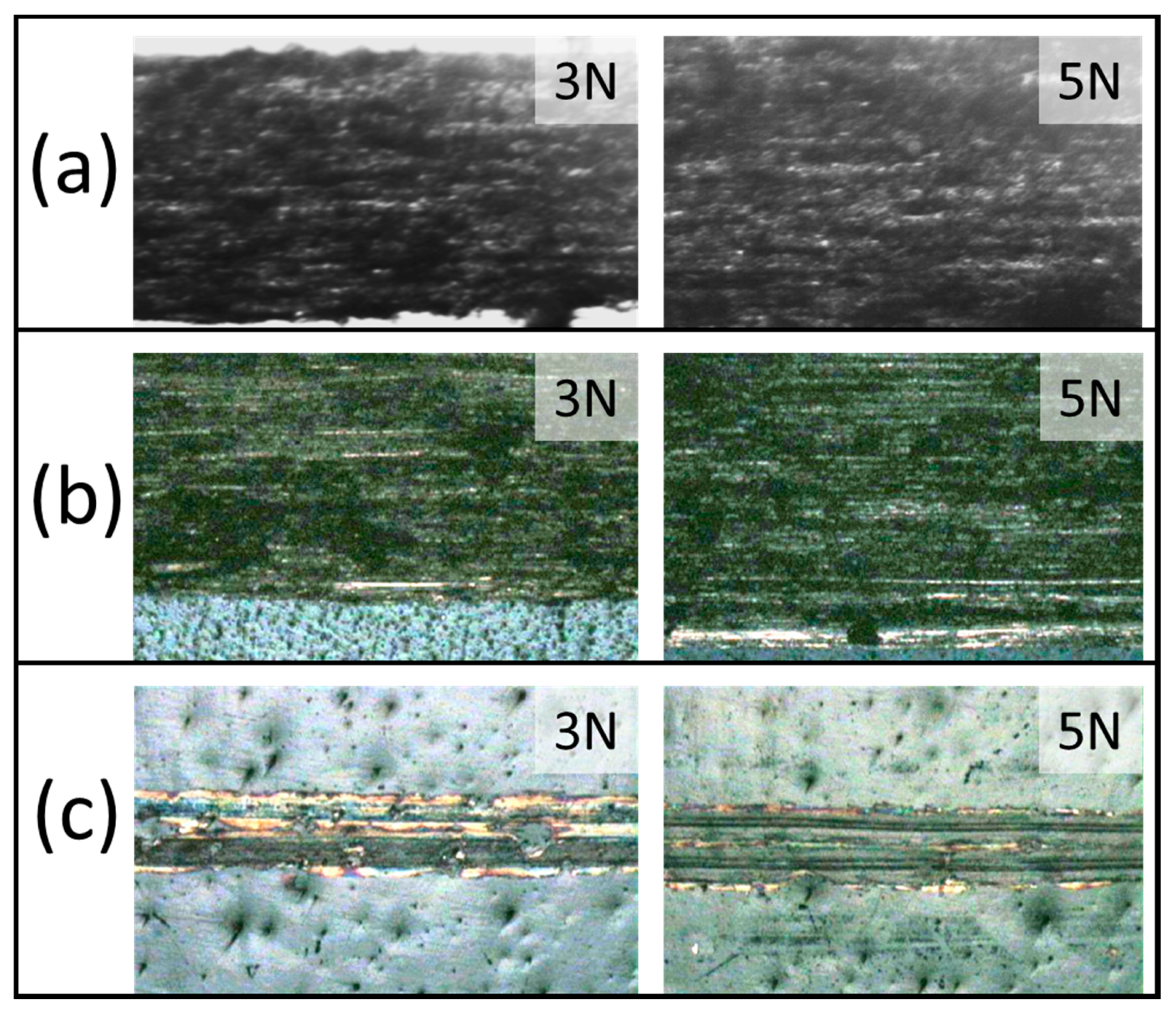
3.6. Tribological Properties

As the Mo-DLC coating deposited at 30 min (Mo content of 6.9 at.%) shows the highest nanohardness, this coating has been tested for tribological behaviour on β-21S Ti-Mo alloy substrate using a ball-on-disk tribometer. Besides, the test has been extended to Mo-DLC coatings deposited for 60 min. Furthermore, friction behaviours of the coatings deposited with 30 and 60 min have been studied at two different stroke loads of 3 and 5 N. Figure 12 shows the evolution of the coefficients of friction of Mo-DLC coatings over time for two different loads. It is observed that the substrate coated for a longer duration of 60 min shows a relatively stable friction-time profile with average coefficients of friction of 0.17 and 0.15, which are lower than 0.62 and 0.43 for bare β-21S Ti-Mo alloy substrate for 3 and 5 N loads, respectively as summarized in Table 2. On the other hand, in the case of coating with a shorter duration of 30 min, the coefficient of friction abruptly increases from a steady state of 0.2 and 0.17 to substrate values of 0.64 and 0.63. The sudden increase in friction coefficient is due to loss and transfer of the coating materials on the counter part (ball) during wear stroke [87]. It is also known that tribochemical reaction at the point of contact between ball and coating can deteriorate the Mo-DLC layer [67]. This chemical reaction can create a third superficial layer called a tribolayer that acts as a wear resistant. Graphitization can also take place that reduces the friction coefficient, which is observed in the case of Ti-doped DLC [88] and Zr-doped DLC coatings [89]. In the present study, Mo-DLC coating obtained with 60 min duration shows a constant friction coefficient, which is probably due to graphitization from tribochemical reactions occurred by transformation of sp3 C to sp2 carbon in the coatings, possibly by thermal process during wear stroke [90].
Figure 13 presents typical 3D micrographs of wear tracks and their corresponding 2D cross-section line profiles of bare β-21S, Mo-DLC-coated substrates at 30 and 60 min duration after friction test. Wear loss has been estimated as per ASTM G 133 standard. Table 3 lists the wear loss values of bare substrate and two Mo-DLC-coated substrates. For the coating with 30 min deposition at 3 N load, it is observed that coated substrate shows a wear loss of about 0.0025 mm3 compared to bare substrate wear loss of 0.00475 mm3, whereas with 5 N load, the wear loss is 0.0095 mm3 that is comparatively less than 0.015 mm3 of the bare substrate.
Figure 14 shows the optical micrographs of wear tracks of Mo-DLC-coated β-21S Ti-Mo alloy substrate and uncoated substrate. The wear track on the bare substrate shows abrasive wear with a highly rough and scratchy surface. On the other hand, wear tracks of coated substrates are found to be smoother than bare substrate, which may be due to adhesive wear. Thus, it can be inferred from the optical images that the wear tracks are an abrasive kind for substrate and an adhesive for coated substrate.
Raman spectroscopic analyses have been carried out on the wear tracks to throw the light on the changes in the characteristics of material during the friction process. Figure 15 displays the Raman spectra of as-deposited coatings and the wear track of the same coatings. The wear track of the substrate with Mo-DLC coating for 30 min deposition shows no carbon signal, which clearly indicates that coating is completely removed during wear stroke. However, substrate coated for 60 min deposition shows low intense carbon peaks, indicating the presence of carbon bonds after frictional testing formed during wear stroke. This is because of graphitization induced from the wear process as observed by Müller et al., in their coating [90]. Thus, Mo-DLC coatings deposited for 60 min duration shows superior tribological performance in terms of wear loss and the lowest coefficient of friction on a titanium β-21S alloy.

4. Conclusions

Molybdenum-doped diamond-like carbon coatings have successfully been deposited using PECVD with pulsed-DC magnetron sputtering of molybdenum target particularly on titanium β-21S alloy (Ti–15Mo–3Nb–3Al–0.2Si). Three different Mo contents (3.9, 6.9, and 16.2 at.%) have been incorporated by varying the pulse duration of sputtering bipolar pulse as determined from chemical analysis through XPS. Mo is present in carbidic form, Mo5+, and Mo6+ oxidation states as observed in XPS studies. The deposited coatings are also found to be more graphitic at a higher Mo content along with the presence of its carbide phase as evidenced through XRD studies. Moreover, surface morphology and topography measurements reveal that the coatings are, in general, smooth, with roughness ranging from 0.7–1.2 nm. Results obtained from Raman spectroscopy studies on Mo-DLC coatings with three Mo contents are complimentary to XPS results revealing that the coatings behave with a more graphite-like nature with increase in Mo content. Furthermore, nanoindentation measurements show a hardness ranging around ~18–19 GPa with no significant increase with higher Mo content. Finally, the ball-on-disk wear testing shows low coefficient of friction of about ~0.15 than β-21S Ti-Mo alloy and coating behaves like adhesive wear on the counter surface with negligible wear loss.

Author Contributions

D.B.P.—Investigation and writing-original draft, L.M.—Formal analysis, validation, and writing-original draft, P.G.—Investigation and formal analysis, P.B.—Formal analysis, validation, and writing-review & editing, C.A.—Conceptualization, funding acquisition, project administration, and supervision, H.C.B.—Funding acquisition, Project administration, and resources. All authors have read and agreed to the published version of the manuscript.

Funding

This work was carried out under CSIR network project (ESC-01-01).

Acknowledgments

The authors would like to thank the Director, CSIR–National Aerospace Laboratories, Bengaluru for his support and permission to publish the work. We thank Head, Surface Engineering Division, CSIR–National Aerospace Laboratories for his constant support and encouragement. The authors would like to thank Siju John, G. Srinivas, N.T. Manikandanath, V. Praveen Kumar, and M. Muniprakash for FESEM, XRD, Raman spectroscopy, 3D profilometry, and wear studies, respectively.

Conflicts of Interest

Authors declare no conflict of interest.

References

  1. Viswanathan, S.; Mohan, L.; Bera, P.; Shanthiswaroop, S.; Muniprakash, M.; Barshilia, H.C.; Anandan, C. Corrosion and wear resistance properties of multilayered diamond-like carbon nanocomposite coating. Surf. Interface Anal. 2018, 50, 265–276. [Google Scholar] [CrossRef]
  2. Viswanathan, S.; Mohan, L.; Bera, P.; Kumar, V.P.; Barshilia, H.C.; Anandan, C. Corrosion and wear behaviors of Cr-doped diamond-like carbon coatings. J. Mater. Eng. Perform. 2017, 26, 3633–3647. [Google Scholar] [CrossRef]
  3. Viswanathan, S.; Mohan, L.; Chakraborty, M.; Mandal, C.; Bera, P.; Aruna, S.T.; Anandan, C. Carbon plasma immersion ion implantation and DLC deposition on Ni−Ti alloy. Mater. Manuf. Process. 2018, 33, 1121–1127. [Google Scholar] [CrossRef]
  4. Viswanathan, S.; Reddy, M.M.; Mohan, L.; Bera, P.; Barshilia, H.C.; Anandan, C. Corrosion and wear properties of Ti/Tetrahedral amorphous carbon multilayered coating. J. Bio Tribo Corros. 2017, 3, 39. [Google Scholar] [CrossRef]
  5. Maerten, T.; Jaoul, C.; Oltra, R.; Duport, P.; Le Niniven, C.; Tristant, P.; Meunier, F.; Jarry, O. Micrometric growth defects of DLC thin films. J. Carbon Res. 2019, 5, 73. [Google Scholar] [CrossRef] [Green Version]
  6. Anandan, C.; Mohan, L.; Babu, P.D. Electrochemical studies and growth of apatite on molybdenum doped DLC coatings on titanium alloy β-21S. Appl. Surf. Sci. 2014, 296, 86–94. [Google Scholar] [CrossRef] [Green Version]
  7. Gnanavel, S.; Ponnusamy, S.; Mohan, L.; Radhika, R.; Muthamizhchelvan, C.; Ramasubramanian, K. Electrochemical behavior of biomedical titanium alloys coated with diamond carbon in Hanks’ solution. J. Mater. Eng. Perform. 2018, 27, 1635–1641. [Google Scholar] [CrossRef]
  8. Mohan, L.; Babu, P.D.; Kumar, P.; Anandan, C. Influence of zirconium doping on the growth of apatite and corrosion behavior of DLC-coated titanium alloy Ti-13Nb-13Zr. Surf. Interface Anal. 2013, 45, 1785–1791. [Google Scholar] [CrossRef]
  9. Mohan, L.; Anandan, C.; Grips, V.K.W. Corrosion behavior of titanium alloy beta-21S coated with diamond like carbon in Hank’s solution. Appl. Surf. Sci. 2012, 258, 6331–6340. [Google Scholar] [CrossRef]
  10. Gachon, Y.; Héau, C. Study of mechanical behavior of diamond-like carbon coatings by several instrumented tribometers. Thin Solid Films 2000, 377–378, 360–365. [Google Scholar] [CrossRef]
  11. Wang, D.; Chang, C.; Ho, W. Characterization of hydrogen-free diamond-like carbon flms deposited by pulsed plasma technology. Thin Solid Films 1999, 355–356, 246–251. [Google Scholar] [CrossRef]
  12. Grill, A. Diamond-like carbon: State of the art. Diam. Relat. Mater. 1999, 8, 428–434. [Google Scholar] [CrossRef]
  13. Roy, R.K.; Lee, K. Biomedical applications of diamond-like carbon coatings: A Review. J. Biomed. Mater. Res. B 2007, 1, 72–84. [Google Scholar] [CrossRef] [PubMed]
  14. Ching, H.A.; Choudhury, D.; Nine, M.J.; Osman, N.A.A. Effects of surface coating on reducing friction and wear of orthopaedic implants. Sci. Technol. Adv. Mater. 2014, 15, 014402. [Google Scholar] [CrossRef] [Green Version]
  15. Wei, Q.; Sharma, A.; Sankar, J.; Narayan, J. Mechanical properties of diamond-like carbon composite thin films prepared by pulsed laser deposition. Compos. B Eng. 1999, 30, 675–684. [Google Scholar] [CrossRef]
  16. Aizawa, T.; Wasa, K.; Nogami, Y. Plasma oxidation printing into DLC and graphite for surface functionalization. J. Carbon Res. 2019, 5, 11. [Google Scholar] [CrossRef] [Green Version]
  17. Racine, B.; Benlahsen, M.; Zellama, K.; Goudeau, P.; Zarrabian, M.; Turban, G. Effect of the hydrogen on the intrinsic stress in hydrogenated amorphous carbon films deposited from an electron cyclotron resonance plasma. Appl. Phys. Lett. 1998, 73, 3226–3228. [Google Scholar] [CrossRef]
  18. Chang, L.C.; Wang, Y.D. Microstructure and adhesion characteristics of diamond-like carbon films deposited on steel substrates. Diam. Relat. Mater. 2001, 10, 1528–1534. [Google Scholar] [CrossRef]
  19. Choy, K.; Felix, E. Functionally graded diamond-like carbon coatings on metallic substrates. Mater. Sci. Eng. A 2000, 278, 162–169. [Google Scholar] [CrossRef]
  20. Khamseh, S.; Alibakhshi, E.; Mahdavian, M.; Saeb, M.R.; Vahabi, H.; Kokanyan, N.; Laheurte, P. Magnetron-sputtered copper/diamond-like carbon composite thin films with super anti-corrosion properties. Surf. Coat. Technol. 2018, 333, 148–157. [Google Scholar] [CrossRef]
  21. Jing, P.P.; Gong, Y.L.; Deng, Q.Y.; Zhang, Y.Z.; Huang, N.; Leng, Y.X. The formation of the “rod-like wear debris” and tribological properties of Ag-doped diamond-like carbon films fabricated by a high-power pulsed plasma vapor deposition technique. Vacuum 2020, 173, 109125. [Google Scholar] [CrossRef]
  22. Ray, S.C.; Pong, W.F.; Papakonstantinou, P. Iron, nitrogen and silicon doped diamond like carbon (DLC) thin films: A comparative study. Thin Solid Films 2016, 610, 42–47. [Google Scholar] [CrossRef]
  23. Wang, P.; Wang, X.; Chen, Y.; Zhang, G.; Liu, W.; Zhang, J. The effect of applied negative bias voltage on the structure of Ti-doped a-C:H films deposited by FCVA. Appl. Surf. Sci. 2007, 253, 3722–3726. [Google Scholar] [CrossRef]
  24. Singh, V.; Palshin, V.; Tittsworth, R.C.; Meletis, E.I. Local structure of composite Cr-containing diamond-like carbon thin films. Carbon 2006, 44, 1280–1286. [Google Scholar] [CrossRef]
  25. Podgornik, B.; Hren, D.; Vižintin, J. Low-friction behaviour of boundary-lubricated diamond-like carbon coatings containing tungsten. Thin Solid Films 2005, 476, 92–100. [Google Scholar] [CrossRef]
  26. Chen, X.; Peng, Z.; Fu, Z.; Wu, S.; Yue, W.; Wang, C. Microstructural, mechanical and tribological properties of tungsten-gradually doped diamond-like carbon films with functionally graded interlayers. Surf. Coat. Technol. 2011, 205, 3631–3638. [Google Scholar] [CrossRef]
  27. Fu, R.K.Y.; Mei, Y.F.; Fu, M.Y.; Liu, X.Y.; Chu, P.K. Thermal stability of metal-doped diamond-like carbon fabricated by dual plasma deposition. Diam. Relat. Mater. 2005, 14, 1489–1493. [Google Scholar] [CrossRef]
  28. Wei, Q.; Narayan, R.J.; Narayan, J.; Sankar, J.; Sharma, A.K. Improvement of wear resistance of pulsed laser deposited diamond-like carbon films through incorporation of metals. Mat. Sci. Eng. B 1998, 53, 262–266. [Google Scholar] [CrossRef]
  29. Khan, M.I.; Rasheed, I.; Naeem, M.A.; Majeed, S.; Mustafa, G.M.; Fatima, M.; Mahmood, A.; Al-Masry, W.; Iqbal, M.; Kattan, N.A.; et al. Structural, electrical and mechanical behavior evaluation of palladium doped diamond like carbon thin films. J. Mater. Res. Technol. 2020, 9, 8289–8295. [Google Scholar] [CrossRef]
  30. Zhang, M.; Xie, T.; Qian, X.; Zhu, Y.; Liu, X. Mechanical properties and biocompatibility of Ti-doped diamond-like carbon films. ACS Omega 2020, 5, 22772–22777. [Google Scholar] [CrossRef]
  31. Chaus, A.S.; Fedosenko, T.N.; Rogachev, A.V.; Čaplovič, Ľ. Surface, microstructure and optical properties of copper-doped diamond-like carbon coating deposited in pulsed cathodic arc plasma. Diam. Relat. Mater. 2014, 42, 64–70. [Google Scholar] [CrossRef]
  32. Santana, J.A.C.; Skomski, R.; Singh, V.; Palshin, V.; Petukhov, A.; Losovyj, Y.B.; Sokolov, A.; Dowben, P.A.; Ketsman, I. Magnetism of Cr-doped diamond-like carbon. J. Appl. Phys. 2009, 105, 07A930. [Google Scholar] [CrossRef] [Green Version]
  33. Gnanavel, S.; Ponnusamy, S.; Mohan, L. Biocompatible response of hydroxyapatite coated on near-β titanium alloys by E-beam evaporation method. Biocatal. Agric. Biotechnol. 2018, 15, 364–369. [Google Scholar] [CrossRef]
  34. Gnanavel, S.; Ponnusamy, S.; Mohan, L.; Muthamizhchelvan, C. In vitro corrosion behaviour of Ti–6Al–4V and 316L stainless steel alloys for biomedical implant applications. J. Bio Tribo Corros. 2018, 4, 1. [Google Scholar] [CrossRef]
  35. Mohan, L.; Chakraborty, M.; Viswanathan, S.; Mandal, C.; Bera, P.; Aruna, S.T.; Anandan, C. Corrosion, wear, and cell culture studies of oxygen ion implanted Ni-Ti alloy. Surf. Interface Anal. 2017, 49, 828–836. [Google Scholar] [CrossRef]
  36. Anandan, C.; Mohan, L. Effect of postnitride annealing on wear and corrosion behavior of titanium alloy Ti-6Al-4V. J. Mater. Eng. Perform. 2016, 25, 4416–4424. [Google Scholar] [CrossRef]
  37. Mohan, L.; Anandan, C. Wear and corrosion behavior of oxygen implanted biomedical titanium alloy Ti-13Nb-13Zr. Appl. Surf. Sci. 2013, 282, 281–290. [Google Scholar] [CrossRef]
  38. Mohan, L.; Durgalakshmi, D.; Geetha, M.; Narayanan, T.S.N.S.; Asokamani, R. Electrophoretic deposition of nanocomposite (HAp + TiO2) on titanium alloy for biomedical applications. Ceram. Int. 2012, 38, 3435–3443. [Google Scholar] [CrossRef]
  39. Anandan, C.; Babu, P.D.; Mohan, L. Effect of gas composition on nitriding and wear behavior of nitrided titanium alloy Ti-15V-3Cr-3Al-3Sn. J. Mater. Eng. Perform. 2013, 22, 2623–2633. [Google Scholar] [CrossRef]
  40. Mohan, L.; Dennis, C.; Padmapriya, N.; Anandan, C.; Rajendran, N. Effect of electrolyte temperature and anodization time on formation of TiO2 nanotubes for biomedical applications. Mater. Today Commun. 2020, 23, 101103. [Google Scholar] [CrossRef]
  41. Niinomi, M.; Kuroda, D.; Fukunaga, K.; Morinaga, M.; Kato, Y.; Yashiro, T.; Suzuki, A. Corrosion wear fracture of new β type biomedical titanium alloys. Mater. Sci. Eng. A 1999, 263, 193–199. [Google Scholar] [CrossRef]
  42. Mohan, L.; Raja, M.D.; Uma, T.S.; Rajendran, N.; Anandan, C. In-vitro biocompatibility studies of plasma-nitrided titanium alloy β-21S using fibroblast cells. J. Mater. Eng. Perform. 2016, 25, 1508–1514. [Google Scholar] [CrossRef]
  43. Oliveira, N.T.C.; Aleixo, G.; Caram, R.; Guastaldi, A.C. Development of Ti–Mo alloys for biomedical applications: Microstructure and electrochemical characterization. Mater. Sci. Eng. A 2007, 452–453, 727–731. [Google Scholar] [CrossRef]
  44. Sung, B.-S.; Park, T.-E.; Yun, Y.-H. Microstructures and electrochemical behavior of Ti-Mo alloys for biomaterials. Adv. Mater. Sci. Eng. 2015, 2015, 872730. [Google Scholar] [CrossRef] [Green Version]
  45. Mohan, L.; Anandan, C. Effect of gas composition on corrosion behavior and growth of apatite on plasma nitrided titanium alloy beta-21S. Appl. Surf. Sci. 2013, 268, 288–296. [Google Scholar] [CrossRef]
  46. Anandan, C.; Mohan, L. In vitro corrosion behavior and apatite growth of oxygen plasma ion implanted titanium alloy β-21S. J. Mater. Eng. Perform. 2013, 22, 3507–3516. [Google Scholar] [CrossRef]
  47. Mohan, L.; Anandan, C.; Grips, V.K.W. Investigation of electrochemical behavior of nitrogen implanted Ti-15Mo-3Nb-3Al alloy in Hank’s solution. J. Mater. Sci. Mater. Med. 2013, 24, 623–633. [Google Scholar] [CrossRef]
  48. Luo, Y.; Ge, S.; Jin, Z.; Fisher, J. Effect of surface modification on surface properties and tribological behaviours of titanium alloys. Proc. Inst. Mech. Eng. Part J J. Eng. Tribol. 2009, 223, 311–316. [Google Scholar] [CrossRef]
  49. Uwais, Z.A.; Hussein, M.A.; Samad, M.A.; Al-Aqeeli, N. Surface modification of metallic biomaterials for better tribological properties: A review. Arab. J. Sci. Eng. 2017, 42, 4493–4512. [Google Scholar] [CrossRef]
  50. Tallant, D.R.; Parmeter, J.E.; Siegal, M.P.; Simpson, R.L. The thermal stability of diamond-like carbon. Diam. Relat. Mater. 1995, 4, 191–199. [Google Scholar] [CrossRef]
  51. Ji, L.; Li, H.; Zhao, F.; Chen, J.; Zhou, H. Microstructure and mechanical properties of Mo/DLC nanocomposite films. Diam. Relat. Mater. 2008, 17, 1949–1954. [Google Scholar] [CrossRef]
  52. Rusli, H.; Yoon, S.F.; Huang, Q.F.; Ahn, J.; Zhang, Q.; Yang, H.; Wu, Y.S.; Teo, E.J.; Osipowicz, T.; Watt, F. Metal-containing amorphous carbon film development using electron cyclotron resonance CVD. Diam. Relat. Mater. 2001, 10, 132–138. [Google Scholar] [CrossRef]
  53. Gwo, J.; Chu, C.L.; Tsai, M.J.; Lee, S. Enhancement of Ti-containing hydrogenated carbon (TiC:H) films by high-power plasma-sputtering. Appl. Surf. Sci. 2012, 258, 3433–3437. [Google Scholar] [CrossRef]
  54. Kumar, P.; Babu, P.D.; Mohan, L.; Anandan, C.; Grips, V.K.W. Wear and corrosion behavior of Zr-Doped DLC on Ti-13Zr-13Nb biomedical alloy. J. Mater. Eng. Perform. 2013, 22, 283–293. [Google Scholar] [CrossRef]
  55. Panda, M.; Krishnan, R.; Krishna, N.G.; Amirthapandian, S.; Magudapathy, P.; Kamruddin, M. Tuning the tribological property of PLD deposited DLC-Au nanocomposite thin films. Cearm. Int. 2019, 45, 8847–8855. [Google Scholar] [CrossRef]
  56. Qi, F.; Leng, Y.X.; Sun, H.; Huang, N. Mechanical properties of DLC/Ti-O bilayer films. IEEE Trans. Plasma Sci. 2009, 37, 1136–1139. [Google Scholar] [CrossRef]
  57. Küttel, O.M.; Martinu, L.; Poitras, D.; Klemberg-Sapieha, J.E.; Wertheimer, M.R. Diamond-like carbon films deposited in a dual microwave-radio-frequency plasma. Mater. Sci. Eng. B 1992, 11, 321–324. [Google Scholar] [CrossRef]
  58. Mazare, A.; Anghel, A.; Surdu-Bob, C.; Totea, G.; Demetrescu, I.; Ionita, D. Silver doped diamond-like carbon antibacterial and corrosion resistance coatings on titanium. Thin Solid Films 2018, 657, 16–23. [Google Scholar] [CrossRef]
  59. Swiatek, L.; Olejnik, A.; Grabarczyk, J.; Jedrzejczak, A.; Sobczyk-Guzenda, A.; Kaminska, M.; Jakubowski, W.; Szymanski, W.; Bociaga, D. Multi-doped diamond like-carbon coatings (DLC-Si/Ag) for biomedical applications fabricated using the modified chemical vapour deposition method. Diam. Relat. Mater. 2016, 67, 54–62. [Google Scholar] [CrossRef]
  60. Bai, W.Q.; Li, L.L.; Xie, Y.J.; Liu, D.G.; Wang, X.L.; Jin, G.; Tu, J.P. Corrosion and tribocorrosion performance of M (M = Ta, Ti) doped amorphous carbon multilayers in Hank’s solution. Surf. Coat. Technol. 2016, 305, 11–22. [Google Scholar] [CrossRef]
  61. Wang, Z.; Zhang, H.; Guo, C.; Liu, W.; Yang, Z.; Sun, X.; Zhang, Z.; Jiang, F. Effect of molybdenum addition on the precipitation of carbides in the austenite matrix of titanium micro-alloyed steels. J. Mater. Sci. 2016, 51, 4996–5007. [Google Scholar] [CrossRef]
  62. Tang, X.S.; Wang, H.J.; Feng, L.; Shao, L.X.; Zou, C.W. Mo doped DLC nanocomposite coatings with improved mechanical and blood compatibility properties. Appl. Surf. Sci. 2014, 311, 758–762. [Google Scholar] [CrossRef]
  63. Ribeiro, A.M.; Flores-Sahagun, T.H.S.; Paredes, R.C. A perspective on molybdenum biocompatibility and antimicrobial activity for applications in implants. J. Mater. Sci. 2016, 51, 2806–2816. [Google Scholar] [CrossRef]
  64. Fu, R.K.Y.; Mei, Y.; Shen, L.; Siu, G.; Chu, P.K.; Cheung, W.; Wong, S. Molybdenum–carbon film fabricated using metal cathodic arc and acetylene dual plasma deposition. Surf. Coat. Technol. 2004, 186, 112–117. [Google Scholar] [CrossRef]
  65. Byon, E.; Kim, J.-K.; Rha, J.-J.; Kwon, S.-C.; Mu, Z.; Liu, C.; Li, G. Effect of metal ion implantation on thermal instability of diamond-like carbon films. Surf. Coat. Technol. 2007, 201, 6670–6673. [Google Scholar] [CrossRef]
  66. Kolawole, F.O.; Ramirez, M.A.; Kolawole, S.K.; Varela, L.B.; Tschiptschin, A.P. Deposition and characterization of molybdenum oxide (MoO3) nanoparticles incorporated diamond-like carbon coatings using pulsed-DC PECVD. Mater. Lett. 2020, 278, 128420. [Google Scholar] [CrossRef]
  67. Wang, L.L.; Wang, R.Y.; Yan, S.J.; Zhang, R.; Yang, B.; Zhang, Z.D.; Huang, Z.H.; Fu, D.J. Structure and properties of Mo containing diamond-like carbon films produced by ion source assisted cathodic arc ion-plating. Appl. Surf. Sci. 2013, 286, 109–114. [Google Scholar] [CrossRef]
  68. Oliver, W.C.; Pharr, G.M. Measurement of hardness and elastic modulus by instrumented indentation: Advances in understanding and refinements to methodology. J. Mater. Res. 2004, 19, 3–20. [Google Scholar] [CrossRef]
  69. Mérel, P.; Tabbal, M.; Chaker, M.; Moisa, S.; Margot, J. Direct evaluation of the sp3 content in diamond-like-carbon films by XPS. Appl. Surf. Sci. 1998, 136, 105–110. [Google Scholar] [CrossRef]
  70. Haerle, R.; Riedo, E.; Pasquarello, A.; Baldereschi, A. sp2/sp3 hybridization ratio in amorphous carbon from C 1s core-level shifts: X-ray photoelectron spectroscopy and first-principles calculation. Phys. Rev. B 2001, 65, 045101. [Google Scholar] [CrossRef]
  71. Zhang, L.; Ball, M.R.; Liu, Y.; Kuech, T.F.; Huber, G.W.; Mavrikakis, M.; Hermans, I.; Dumesic, J.A. Synthesis gas conversion over Rh/Mo catalysts prepared by atomic layer deposition. ACS Catal. 2019, 9, 1810–1819. [Google Scholar] [CrossRef]
  72. Alhajri, N.S.; Anjum, D.H.; Takanabe, K. Molybdenum carbide–carbon nanocomposites synthesized from a reactive template for electrochemical hydrogen evolution. J. Mater. Chem. A 2014, 2, 10548–10556. [Google Scholar] [CrossRef]
  73. Tai, F.C.; Lee, S.C.; Chen, J.; Wei, C.; Chang, S.H. Multipeak fitting analysis of Raman spectra on DLCH film. J. Raman Spectrosc. 2009, 40, 1055–1059. [Google Scholar] [CrossRef]
  74. Ferrari, A.C.; Robertson, J. Interpretation of Raman spectra of disordered and amorphous carbon. Phys. Rev. B 2000, 61, 14095–14107. [Google Scholar] [CrossRef] [Green Version]
  75. Irmer, G.; Dorner-Reisel, A. Mirco-Raman studies on DLC coatings. Adv. Eng. Mater. 2005, 7, 694–705. [Google Scholar] [CrossRef]
  76. Ferrari, A.C.; Robertson, J. Raman spectroscopy of amorphous, nanostructured, diamond-like carbon, and nanodiamond. Phil. Trans. R. Soc. Lond. A 2004, 362, 2477–2512. [Google Scholar] [CrossRef]
  77. Ferrari, A.C.; Robertson, J. Origin of the 1150−cm−1 Raman mode in nanocrystalline diamond. Phys. Rev. B 2001, 63, 121405. [Google Scholar] [CrossRef]
  78. Chu, P.K.; Li, L. Characterization of amorphous and nanocrystalline carbon films. Mater. Chem. Phys. 2006, 96, 253–277. [Google Scholar] [CrossRef]
  79. Tuinstra, F.; Koenig, J.L. Raman spectrum of graphite. J. Chem. Phys. 1970, 53, 1126–1130. [Google Scholar] [CrossRef] [Green Version]
  80. Cho, N.H.; Veirs, D.K.; Ager, J.W.; Rubin, M.D.; Hopper, C.B.; Bogy, D.B. Effects of substrate temperature on chemical structure of amorphous carbon films. J. Appl. Phys. 1992, 71, 2243–2248. [Google Scholar] [CrossRef]
  81. Robertson, J. Diamond-like amorphous carbon. Mater. Sci. Eng. R 2002, 37, 129–281. [Google Scholar] [CrossRef] [Green Version]
  82. Gayathri, S.; Kumar, N.; Krishnan, R.; Ravindran, T.R.; Amirthapandian, S.; Dash, S.; Tyagi, A.K.; Sridharan, M. Influence of transition metal doping on the tribological properties of pulsed laser deposited DLC films. Ceram. Int. 2015, 41, 1797–1805. [Google Scholar] [CrossRef]
  83. Khun, N.W.; Liu, E.; Yang, G.C.; Ma, W.G.; Jiang, S.P. Structure and corrosion behavior of platinum/ruthenium/nitrogen doped diamondlike carbon thin films. J. Appl. Phys. 2009, 106, 013506. [Google Scholar] [CrossRef] [Green Version]
  84. Casiraghi, C.; Ferrari, A.C.; Robertson, J. Raman spectroscopy of hydrogenated amorphous carbons. Phys. Rev. B 2005, 72, 085401. [Google Scholar] [CrossRef] [Green Version]
  85. Dai, W.; Wu, G.; Wang, A. Preparation, characterization and properties of Cr-incorporated DLC films on magnesium alloy. Diam. Relat. Mater. 2010, 19, 1307–1315. [Google Scholar] [CrossRef]
  86. Veres, M.; Tóth, S.; Koós, M. Grain boundary fine structure of ultrananocrystalline diamond thin films measured by Raman scattering. Appl. Phys. Lett. 2007, 91, 031913. [Google Scholar] [CrossRef]
  87. Voevodin, A.A.; O’Neill, J.P.; Zabinski, J.S. Tribological performance and tribochemistry of nanocrystalline WC/amorphous diamond-like carbon composites. Thin Solid Films 1999, 342, 194–200. [Google Scholar] [CrossRef]
  88. Zhao, F.; Li, H.; Ji, L.; Wang, Y.; Liu, X.; Zhou, H.; Chen, J. Effect of microstructural evolution on mechanical and tribological properties of Ti-doped DLC films: How was an ultralow friction obtained? J. Vac. Sci. Technol. A 2016, 34, 031504. [Google Scholar] [CrossRef]
  89. Vitu, T.; Escudeiro, A.; Polcar, T.; Cavaleiro, A. Sliding properties of Zr-DLC coatings: The effect of tribolayer formation. Surf. Coat. Technol. 2014, 258, 734–745. [Google Scholar] [CrossRef]
  90. Müller, I.C.; Sharp, J.; Rainforth, W.M.; Hovsepian, P.; Ehiasarian, A. Tribological response and characterization of Mo–W doped DLC coating. Wear 2017, 376–377, 1622–1629. [Google Scholar] [CrossRef]
Figure 1. Schematic image of PECVD system used for the deposition of Mo-DLC coatings where TMP—Turbomolecular pump, RP—Roughing pump, RV—Roughing valve, BV—Backing valve, HV—High vacuum valve, and MFC—Mass flow controller.
Carbon 07 00001 g001
Figure 2. Survey spectra of Mo-DLC coatings: (a) 3.9 at.% Mo, (b) 6.9 at.% Mo, and (c) 16.2 at.% Mo.
Carbon 07 00001 g002
Figure 3. Curve-fitted C 1s core level spectra of Mo-DLC coatings: (a) 3.9 at.% Mo and (b) 16.2 at.% Mo.
Carbon 07 00001 g003
Figure 4. Curve-fitted Mo 3d core level spectra of Mo-DLC coatings: (a) 3.9 at.% Mo and (b) 16.2 at.% Mo.
Carbon 07 00001 g004aCarbon 07 00001 g004b
Figure 5. Variation of (a) sp2/sp3 ratios and (b) molybdenum carbide concentrations for different Mo contents in the Mo-DLC coatings.
Carbon 07 00001 g005
Figure 6. XRD patterns of Mo-DLC coatings on Si substrate: (a) Si substrate, (b) 3.9 at.% Mo, and (c) 16.2 at.% Mo.
Carbon 07 00001 g006
Figure 7. Surface morphologies of Mo-DLC coatings on Si substrate: (a) 3.9 at.% Mo and (b) 16.2 at.% Mo.
Carbon 07 00001 g007
Figure 8. Surface topographies of Mo-DLC coatings on Si substrate: (a) 3.9 at.% Mo and (b) 16.2 at.% Mo.
Carbon 07 00001 g008
Figure 9. (a) Raman spectra of Mo-DLC coatings for different Mo contents (b) Gaussian fitting of Raman spectrum of 3.9 at.% Mo-DLC coating, and (c) corresponding ID/IG and FWHM of G peak evolution with different Mo concentrations in Mo-DLC coatings.
Carbon 07 00001 g009aCarbon 07 00001 g009b
Figure 10. Nanohardness and elastic modulus values of Mo-DLC coatings with different Mo contents.
Carbon 07 00001 g010
Figure 11. Load-displacement curves of 16.2 at.% Mo-DLC coating at various places.
Carbon 07 00001 g011
Figure 12. Coefficient of friction as a function of time for (a) 3N and (b) 5 N loads on Mo-DLC coatings and bare β-21S Ti-Mo alloy substrate.
Carbon 07 00001 g012
Figure 13. 3D wear track and corresponding 2D line profiles at 3 and 5 N loads: (a) bare β-21S (Ti-Mo) alloy substrate, (b) Mo-DLC coating with 30 min deposition, and (c) Mo-DLC coating with 60 min deposition.
Carbon 07 00001 g013aCarbon 07 00001 g013b
Figure 14. Optical micrographs of wear tracks at 3 and 5 N loads: (a) bare β-21S Ti-Mo alloy substrate, (b) Mo-DLC coating with 30 min deposition, and (c) Mo-DLC coating with 60 min deposition.
Carbon 07 00001 g014
Figure 15. Raman spectra of Mo-DLC coatings deposited for (a) 30 min and (b) 60 min with 40% duty cycle, wherein spectra were recorded on coatings and their wear tracks.
Carbon 07 00001 g015
Table 1. Binding energies and relative peak areas of carbon and molybdenum species in Mo-DLC coatings deposited with different duty cycles.
Duty Cycle (%)CoatingC SpeciesBinding Energy of C 1s (eV)Relative Peak Area (%)Mo SpeciesBinding Energy of Mo 3d5/2 (eV)Relative Peak Area (%)
103.9 at.% Mo-DLCMo–C283.43.3Mo–C228.456.2
sp2284.641.5Mo4+229.926.7
sp328544.7Mo6+232.417.1
C–O286.67.2
C=O287.73.3
406.9 at.% Mo-DLCMo–C283.45.7Mo–C228.463.3
sp2284.540.8Mo4+229.821.5
sp328542.5Mo6+232.415.2
C–O286.77.5
C=O287.83.5
8516.2 at.% Mo-DLCMo–C283.511.5Mo–C228.463.5
sp2284.438.3Mo4+229.823.3
sp328535.6Mo6+232.413.2
C–O286.69.1
C=O287.85.5
Table 2. Coefficient of frictions of Mo-DLC coatings on β-21S Ti-Mo substrate.
SampleCoefficient of Friction
3 N5 N
β-21S Ti-Mo0.620.43
Mo-DLC (30 min)0.20.17
Mo-DLC (60 min)0.170.15
Table 3. Estimated wear losses during tribometric measurements for two different loads.
SampleWear Loss (mm3)
3 N5 N
β-21S Ti-Mo0.004750.015
Mo-DLC (30 min)0.00250.0095
Mo-DLC (60 min)Negligible0.00008
Publisher’s Note: MDPI stays neutral with regard to jurisdictional claims in published maps and institutional affiliations.

