Communication

Investigating the Possible Origin of Raman Bands in Defective sp2/sp3 Carbons below 900 cm−1: Phonon Density of States or Double Resonance Mechanism at Play?

1
Aix Marseille Univ, CNRS, PIIM, 13397 Marseille, France
2
Departamento de Ciencia de los Materiales e Ingeniería Metalúrgica y Química Inorgánica, Facultad de Ciencias, Universidad de Cádiz, Campus Río San Pedro S/N, 11510 Puerto Real, Spain
3
Laboratorio de Microscopias Avanzadas (LMA), Instituto de Nanociencia de Aragon, Universidad de Zaragoza, 50018 Zaragoza, Spain
4
Instituto de Ciencias de Materiales Aragón, CSIC-U. Zaragoza, 50009 Zaragoza, Spain
5
ARAID Foundation, 50018 Zaragoza, Spain
6
Department of Precision and Microsystems Engineering, Research Group of Micro and Nano Engineering, Delft University of Technology, Mekelweg 2, 2628 CD Delft, The Netherlands
*
Author to whom correspondence should be addressed.
Submission received: 25 October 2019 / Revised: 18 November 2019 / Accepted: 22 November 2019 / Published: 29 November 2019
(This article belongs to the Special Issue Characterization of Disorder in Carbons)

Abstract

:
Multiwavelength Raman spectroscopy (325, 514, 633 nm) was used to analyze three different kinds of samples containing sp2 and sp3 carbons: chemical vapor deposited diamond films of varying microstructure, a plasma-enhanced chemical vapor deposited hydrogenated amorphous carbon film heated at 500 °C and highly oriented pyrolytic graphite exposed to a radio-frequent deuterium plasma. We found evidence that the lower part of the phonon density of states (PDOS) spectral region (300–900 cm−1) that rises when defects are introduced in crystals can give more information on the structure than expected. For example, the height of the PDOS, taken at 400 cm−1 and compared to the height of the G band, depends on the sp2 content, estimated by electron energy-loss spectroscopy. This ratio measured with 633 nm laser is more intense than with 514 nm laser. It is also correlated for diamond to the relative intensity ratio between the diamond band at 1332 cm−1 and the G band at ≈1500–1600 cm−1 when using 325 nm laser. Moreover, it is found that the shape of the PDOS of the exposed graphite samples is different when changing the wavelength of the laser used, giving evidence of a double resonance mechanism origin with the rise of the associated D3, D4 and D5 bands, which is not the case for a-C:H samples.

1. Introduction

In material science, Raman spectroscopy is widely used to characterize carbon containing samples. There are several reasons for this. Likely the most important reason is its high distinctiveness for sp2 containing materials. Due to a double resonance mechanism involving Dirac cones of graphene like structures, the corresponding Raman cross-section is high [1]. For sp3 based materials, Raman cross-sections are less intensive (nearly two orders of magnitude lower, depending on the wavelength of the laser used [2]). In the case of polycrystalline diamond thin films, the material is more or less transparent for laser light in the visible range, leading to a high amount of material probed that compensates the lower Raman cross-section. To summarize, graphite without disorder only displays one band (G band) at 1582 cm−1 in the 1000–1800 cm−1 spectral range [3] whereas phase-pure diamond displays only one band at 1332 cm−1 [4]. These bands come from phonons at the center of the Brillouin zones, being due to both total energy and momentum conservations during the scattering process plus quantum selection rules involving the crystal symmetry [1]. When disorder is introduced in graphite, a defect induced band (called the D band, D for defect) rises at 1350 cm−1 with a 514 nm laser, as symmetry is broken and quantum selection rule relaxed. The position of this band, contrary to the one related to phonons of the diamond, varies with the wavelength of the laser used. Other bands, due to double resonance mechanism, appear or are modified when introducing defects [5,6]. When the amount of defects is very large, the material starts to behave as an amorphous one [7,8,9]. In this case, the G band is no more at 1582 cm−1 but shifts, broadens and is overlapped, being still intense. For diamond (if poly- or nanocrystalline in nature), other bands can develop in the 1100–1470 cm−1 spectral range and are attributed to trans-polyacetylene and/or the G band [4,10,11]. A recent study dedicated to detonation nanodiamonds investigated the possible origins of this G band [12]. Broadening and shifting can be also introduced by confining phonons in nanometric crystallites, which leads to the introduction of phonons in the Raman spectrum that are far from the Brillouin zone center [12,13] (and references herein).
As presented above, most of the efforts to interpret Raman spectra of these carbonaceous materials are focused above 1000 cm−1 (except maybe for carbon nanotubes where radial breathing modes are of importance but not discussed here). Nonetheless, some advances up to 3200 cm−1 were reported recently for combination bands [14]. However, some studies point to the fact that the spectral region below 1000 cm−1 could also be important to analyze. For aromatic carbons, there are bands due to the double resonance mechanism [5] (called D3, D4, D5 according to Venezuela et al.), that also disperse with the laser used. There are also hydrogen isotopes bonded to aromatic carbons [15,16,17] and bending modes of sp hybridized linear structures [18]. Finally, there are other bands due to the rise of the phonon density of states (PDOS) that should not disperse [8,19,20,21]. The PDOS of diamond [22] and graphite [23] are different due to their different crystal structures. Vibrations of nanoscale fractional graphitic structures in amorphous carbon also lead to a different shape [24]. Moreover, local constrains can modify the shape of the PDOS of strained graphene [25]. The consequence is that these bands coming from the PDOS could be used systematically to better characterize the structure of the material probed, in addition to bands found in more common spectral ranges (i.e., from 1000 cm−1 upwards, as those signatures are more intense). As an example, the sound velocity in graphene was derived recently with a method involving a combination of acoustic phonons in the range 1650–2150 cm−1 [26], but these acoustic phonons may in principle be also accessible below 1000 cm−1 when the PDOS rises. An in-depth study of this spectral region would allow us to have access to a wealth of information to study, for instance, among many other examples, strain engineering in graphene [27], 3D porous graphene-like structures for supercapacitors [28] and sensing applications [29]. However, the main difficulty to overcome is the low intensity of these bands.
In this short communication, we aim to improve the knowledge about the low-/medium- frequency modes range of carbonaceous materials. For achieving this goal, we will investigate three different kinds of samples containing a mixture of sp2 and sp3 carbons: chemical vapor deposited (CVD) diamond films grown with different CH4/H2 gas precursor flows, plasma-enhanced chemical vapor deposited (PECVD) hydrogenated amorphous carbon film heated at 500 °C for up to 1000 min and highly oriented pyrolytic graphite (HOPG) exposed to a RF deuterium plasma. Energy Electron Loss Spectroscopy (EELS), very useful to obtain sp2/sp3 ratio [30,31], has been used for amorphous carbon and diamond films analyzed in this study. We show that the spectral region below 1000 cm·1 can be used to differentiate one sample from the other and provide more information on their structure. The main goal of this work is to initiate further studies in order to understand completely the link between spectral features and defects.

2. Materials and Methods

2.1. Sample Preparation

2.1.1. CVD Diamond

CVD diamond films with different microstructure but similar nominal layer thickness of about 3.5 μm were grown on seeded silicon substrates in a home-built hot-filament CVD reactor using a systematically varied methane-to-hydrogen gas mixture of 1.0, 2.0 and 3.0 vol.%, respectively, in a total gas flow of 304.5 SCCM (standard cubic centimeters per minute). Seeding of the mirror-polished p-type silicon (100) samples was done in an ultrasonic bath (Ney Dental Inc. model 28X, Bloomfield, CT, USA) using a suspension of diamond micropowder (particle size 1–2.5 μm) in isopropanol following the procedure described in [32]. The following deposition parameters were maintained throughout: substrate temperature of about 800 °C, filament temperature of 2200 °C, system pressure of 15 mbar, filament-to-substrate distance of 10 ± 2 mm. A freshly prepared pre-carburized tantalum filament of 0.5 mm diameter was used for each diamond film growth.

2.1.2. Hydrogenated Amorphous Carbon

A hard amorphous, hydrogenated carbon film (a-C:H), with a thickness around 300 nm and an initial hydrogen content close to 30 at.% was deposited by PECVD on a Si wafer on the driven electrode of a capacitively coupled radio frequency plasma (13.56 MHz) in pure methane at 2 Pa and applying a DC self-bias of −200 V [33,34]. To vary the hydrogen content and microstructure, the grown sample was cut in several smaller pieces that were heated under 1.5 bar argon atmosphere at 500 °C during 15, 120 and 1000 min [31].

2.1.3. Implanted HOPG

Highly Oriented Pyrolytic Graphite (HOPG) samples were disposed on a home made DC biased sample holder and exposed to a deuterium RF plasma (0.2 Pa, 100W) during 15 min using the set up described in [35,36]. Due to the plasma sheath, ions are bombarding the sample perpendicularly. Mass spectrometry measurements revealed that the dominant positive ion was D2+. As ions dissociate at impact on the surface, the ion energy is shared between the fragments. Impact energy of 250 eV/D was obtained by setting the bias voltage at around 500 V, and 400 eV/D impact energy was obtained with a bias voltage around 800 V [17]. The ion flux was estimated by using a Langmuir probe and was found to be φion ~1014 cm−2 s−1. The ion fluence was then about 2 × 10¹⁷ D/cm2. Implantation depths are estimated to be ~10 nm for 250 eV and ~15 nm for 400 eV (see [17] for more details).

2.2. Sample Characterization

2.2.1. Electron Microscopy and EELS Study

TEM samples were prepared in the cross-section geometry; they were mechanically thinned down using a tripod polisher and then ion-milled in a GATAN-PIPS apparatus. The EELS experiments and data analysis for a:C-H materials have been detailed elsewhere [31]. Briefly, EELS spectra were acquired on a FEI Tecnai F30 operating at 300 kV equipped with a Gatan Tridiem 863 spectrometer and liquid nitrogen temperature. Convergence and collection angles were 6.1 and 5.9 mrad, respectively. Background subtraction for the C-K edge was performed by modeling the usual inverse power law function, and the multiple scattering was then removed by Fourier-ratio deconvolution. The π peak was modeled by using a sum of Gaussian functions of equal standard deviation and separated by 0.5 eV as described previously [30]. The R ratio defined by R = Iπ*(ΔE)/I(π*(ΔE)+σ*(ΔE)) was determined by area integration from 282 to 305 eV. The sp2 fraction was then calculated by using the following relation sp2% = R/RREF, where RREF is the R ratio obtained experimentally from a HOPG reference sample and corrected to take into account the variation of R as a function of the tilt angle [31]. EELS experiments on CVD diamond thin films were performed by using a FEI Titan Cube microscope operating at 80 kV, equipped with a Cs image corrector and a Gatan Tridiem spectrometer and at liquid nitrogen temperature to hinder carbon contamination. Convergence and collection angles were 4.6 and 14.5 mrad, respectively. The same procedure was applied to quantify the sp2 fraction. For this purpose, a new value of RREF was determined to take into account the variation of accelerating voltage and experimental geometry.

2.2.2. Raman Spectroscopy

Raman spectra were obtained by using a HR800 setup from the Horiba Jobin Yvon company. Lasers with 633, 514 and 325 nm wavelength were used. For the 633 and 514 nm wavelengths, a ×100 objective was used whereas for the 325 nm wavelength, a ×40 objective was used. The spectra were recorded after adjusting carefully the power so that the samples did not evolve under the laser beam. The maximum power used was ≈1 mW/μm2 but for some spectra it was 10 times lower. For the 325 nm wavelength, we took an extra care by using Raman maps, recording on several places and diminishing the acquisition time per spectrum at a given place and then making an average.

3. Results

3.1. Multiwavelength Analysis in the 1000–1800 cm−1 Spectral Region

The three differently prepared diamond thin films display a very different microstructure and surface morphology as a result of the gas mixture-dependent re-nucleation processes during the CVD growth, which is not investigated here but was shown previously in [37]. The use of 1.0 vol.% CH4/H2 gas mixture resulted in strongly faceted and rough microcrystalline diamond (MCD) with surface grain sizes up to few μm. Faceted NCD with a surface nanograin size of about 30–60 nm was formed using 2.0 vol. % CH4/H2. Non-faceted diamond exhibiting a rounded (‘ballas’) morphology, often called ‘cauliflower’ diamond [38], was obtained using 3.0 vol. % CH4/H2. Samples are labelled D (3%), D (2%) and D (1%). Spectra, displayed in Figure 1, have been normalized to the G band height. For sample D (3%) (see Figure 1a), D and G bands are observed respectively at 1321 and 1583 cm−1, with a very weak kink at 1332 cm−1. For 514 nm and 325 nm, the G band does not shift, neither the band at 1332 cm−1. However, the D band shifts, due to defects related to sp2 domains (the evolution with the laser energy is given in Figure S1 of the Supplementary Information). The D band intensity diminishes relatively to the G band intensity when decreasing the wavelength, according to the behavior known for disordered nanocrystalline graphite [39]. Same trends are observed for the D (2%) sample (Figure 1b) but with a higher diamond band intensity relatively to sp2 carbons. Other bands may be related to transpolyacethylene bands, or to D”, but this is not discussed here [4,14]. The band intensity related to diamond, at 1332 cm−1, increases relatively to the G band when decreasing the wavelength of the laser used, as is known [2,40]. Same trends are much more pronounced for the D (1%) sample (Figure 1c) where the diamond band is 25 times higher than the G band when 325 nm laser light is used. Then, from the qualitative Raman analysis, sample D (1%) contains less sp2 carbons than sample D (2%) which itself contains less sp2 carbons than sample D (3%).
Hydrogenated amorphous carbons have been studied for a long time as well as their thermal evolution. In particular, we showed before how to combine Raman analyses focused on the interpretation of the 1000–1800 cm−1 spectral range together with other techniques in order to reveal refined information related to structure, local chemical environment and composition [11,16,31,41,42,43,44,45]. Doing isotherms at 500 °C for up to 1000 min in argon atmosphere shows that the structure evolves with time. Figure 2 displays the Raman spectra recorded at the three excitation wavelengths for the as deposited sample (Figure 2a), after 15 min (Figure 2b), after 120 min (Figure 2c) and after 1000 min (Figure 2d). For the as deposited sample, the D and G bands are broad and do overlap, and the G band disperses as it is expected for amorphous carbons. Bands become narrower with increasing time and less overlapped. For each given excitation wavelength, the D band becomes more intense relatively to the G band. Finally, the Raman spectra of the aCH (1000′) sample resemble those of sample D (3%), except they do not contain a diamond band. From this, one can conclude that the aromatic sp2 carbons present in these samples should be close in structure, slightly less disordered for aCH (1000′) than for D (3%) according to the D/G ratio. G and D band dispersions are given in Figure S1 of the Supporting Information.
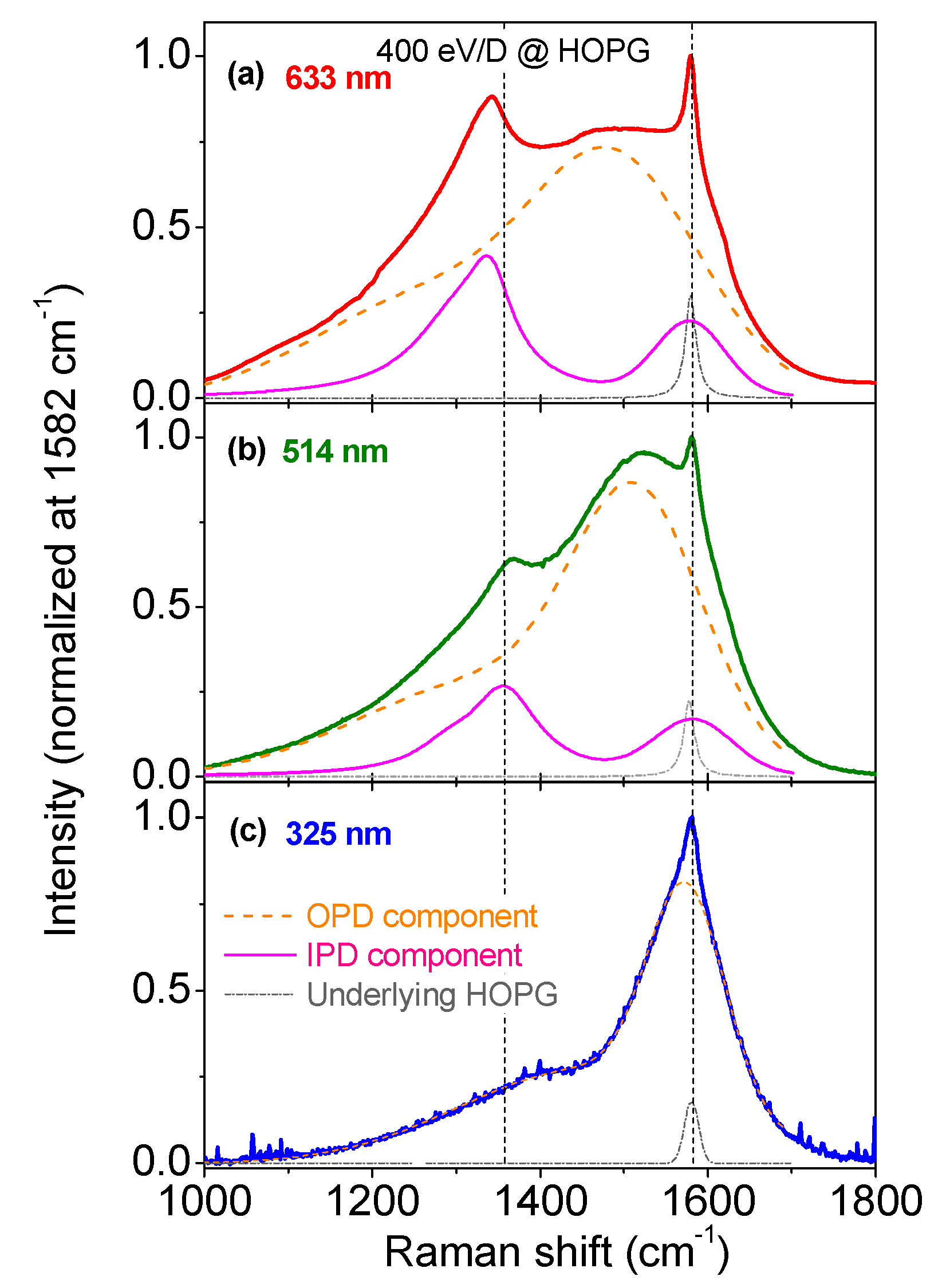
HOPG was implanted by 250 and 400 eV deuterium ions. As it was shown in a previous study, two kinds of coexisting defects were created subsequently to the collision cascade at ion impact (see [17] for details). To give some details, multi-wavelength Raman spectra, displayed in Figure 3, are composed of two broad bands at ≈1250 and 1500 cm−1, plus two other less broad bands 1350 and 1580 cm−1) and a very narrow band at 1582 cm−1. This last band is due to the underlying graphite band that has not been modified by the collision cascade. It means that, as it is seen with all the excitation wavelengths, the overall collision cascade is probed in this measurement and the Raman spectrum gives an integrated view along the depth. We previously showed that these spectra are composed of three main contributions: an unmodified G band from underlying HOPG, two broad D and G overlapping bands coming from “out of plane defects” (OPD) and two thinner D and G bands coming from “in plane defects” (IPD). OPD behaves like amorphous carbon as the broad D and G bands forming the OPD component in the Raman spectrum are overlapping, with a G band dispersion (see [17] for more details). On the contrary, IPD behaves like nanographitic carbon, based on width and dispersion criteria. Note that for the 325 nm data, it was not possible to disentangle the OPD and IPD components because of the proximity between Raman spectral features of nanographites and amorphous carbon [39].

3.2. Multiwavelength Analysis in the PDOS Spectral Region

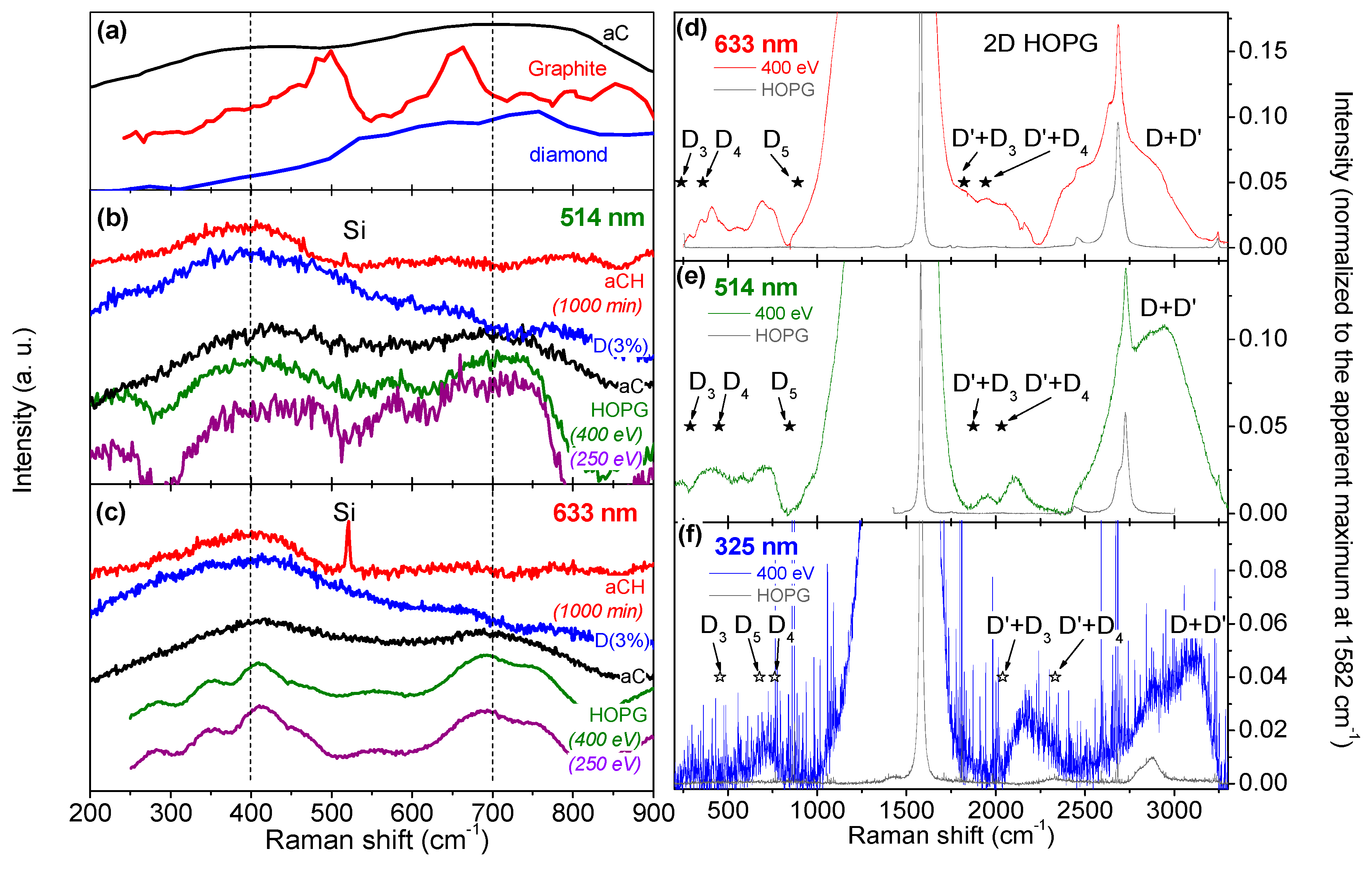
We now turn to the PDOS spectral region. In Figure 4a we have displayed PDOS reference data for graphite [23], diamond [22] and a calculated amorphous carbon [24] up to 900 cm−1. In that spectral window, diamond gives a broad contribution from ≈500 to 800 cm−1, graphite gives two well marked contributions at 500 and 650 cm−1 plus few minor ones (especially one at 850 cm−1), and the simulated amorphous carbon gives two broad and overlapping contributions at 380 and 705 cm−1, respectively. The contribution of graphite at 500 cm−1 is due to out of plane acoustic phonons at the M point of the Brillouin zone whereas the bump close to 850 cm−1 is due to out of plane optical branch at the gamma point, and the one at 650 cm−1 involves both out of plane optical and transverse acoustical phonons at the M point [23]. Note that depending on the method of calculation, some shifts could exist (for example, see in [25] for the case of graphite, where the band at 650 cm−1 could be found at higher wavenumber without introducing strain). In Figure 4b,c we display measurement data obtained from aCH (1000′), D (3%), HOPG implanted at 250 and at 400 eV, and an amorphous carbon that does not contain hydrogen isotopes (see [42]), when excited at respectively 514 and 633 nm. The experimental spectrum corresponding to aC is not varying with the excitation wavelength, and is close to the one simulated and displayed in Figure 4a, being composed of two broad overlapping bands at 400 and 700 cm−1 (the spectrum at 325 nm, not shown, has exactly the same shape in that spectral window). Due to spectral vicinity, it is likely that the broad band at 400 cm−1 has the same origin as the sharp contribution of graphite at 500 cm−1, involving some internal strain that downshifts its position [25].
The experimental spectrum corresponding to aCH (1000′) is similar for the two excitation wavelengths and composed of one broad band at 400 cm−1 plus weaker ripples at higher wavenumber. Note that a sharp silicon band originating from the underlying wafer substrate is present in the spectrum but is less intense for 514 nm than for 633 nm due to the higher absorption coefficient of the aCH layer at 514 nm [42]. The spectrum corresponding to the D (3%) sample is similar with both excitation wavelengths and close to the one of aCH (1000′), as it is primarily composed of a broad band at 400 cm−1. As theoretically diamond should mainly give signatures higher than 500 cm−1, this broad band at 400 cm−1 observed for both aCH (1000′) and D (3%) cannot be attributed to the PDOS of diamond. However, it is close to the large contribution of the PDOS of graphite at 500 cm−1. One then could conclude that this broad band at 400 cm−1 is due to out of plane acoustic phonons at the M point of the Brillouin zone.

3.3. Multiwavelength Analysis of the Exposed HOPG Samples: Double Resonance Mechanism Evidenced

For exposed HOPG, this broad band is present at 400 cm−1 when using the 514 nm excitation wavelength for both the 250 and 400 eV impinging deuterium ions. The band close to 700 cm−1 is also present. In fact, the spectra obtained from exposed HOPG are similar to the spectra of aC. This is consistent with what is observed in the 1000–1800 cm−1 spectral range: an OPD component, behaving as an aC, is observed. If one would stop the analysis at this point, one should conclude that the bands observed below 900 cm−1 are due to the PDOS of graphite, as observed for aC. However, when using a 633 nm excitation wavelength, the broad bands observed at 400 and 700 cm−1 with the 514 nm excitation wavelength are split in two narrower contributions: the 400 cm−1 band is split into two components at 350 cm−1 and 410 cm−1, respectively, and the 700 cm−1 band is split into two contributions at 690 cm−1 and 750 cm−1. This laser excitation dependency was not expected as for all the other samples, the spectral shapes were the same for 514 and 633 nm. A wavelength dependency could suggest in-depth inhomogeneity, but this explanation has to be ruled out as we know that we probe the same (i.e., entire) volume of exposed HOPG with all the wavelengths, as discussed in Section 3.1. As we know the double resonance mechanism effect is at play with graphenic materials, the hypothesis of a double resonance mechanism for ion-exposed HOPG should be investigated as well.
In Figure 4d–f we show a zoom on the spectral data obtained from the 400 eV exposed HOPG sample for excitation wavelengths of 633, 514 and 325 nm, respectively. We also report the position of the D3, D4 and D5 dispersive bands introduced in [5], and their combination bands with D’, D’ involving intravalley double resonance mechanism close to the Dirac cone [5]. Their positions are in the range expected: for excitation at 633 nm, D3 is at 240 cm−1, D4 is at 360 cm−1 and D5 is at 891 cm−1. For 514 nm, it becomes 290, 450 and 845 cm−1 for the same bands, respectively. By doing a linear extrapolation of the data from [5] for 325 nm, the D3 band now falls at 457 cm−1, the D4 band is at 762 cm−1 and the D5 band at 678 cm−1. The spectral interval, defined as the difference between the highest and the lowest of these values is 651 cm−1 for 633 nm, 555 cm−1 for 514 nm and 305 cm−1 for 325 nm. This interval spectrum thus increases with the excitation wavelength. This could explain qualitatively why in our experimental spectrum the bands appear split at 633 nm, but not split at 514 nm. This is confirmed by analyzing the results obtained with the 325 nm laser. Even though the signal to noise ratio is not as good as the ones presented for the other wavelengths, one can see in Figure 4f that there is only one broad band centered at 720 cm−1, as expected if the band below 900 cm−1 for exposed HOPG is due to the double resonance mechanism. Compared to the apparent maximum, normalized at 1, the band’s heights observed below 900 cm−1 are in the range 2% to 3%, which is one to two orders of magnitude higher than what was previously reported [5]. This argument alone could have ruled out the attribution of these bands to D3, D4 and D5, but there is another experimental fact to take into account. We observe strongly overlapping bands between 1820 and 2063 cm−1 using 633 nm excitation laser. When using 514 nm laser excitation, these bands become two non-overlapping bands at 1948 and 2112 cm−1. There is only one asymmetric and very broad band at 2170 cm−1 using 325 nm excitation laser (meaning two overlapped contributions could be present). The spectral interval between the combination D’ + D3 and D’ + D4 bands is 120 cm−1 for 633 nm excitation and 160 cm−1 for 514 nm excitation, according to [5]. If the bands observed are due to the double resonance mechanism, then the band overlap observed at 633 nm and the presence of two separated bands observed at 514 nm could also be explained. Moreover, the height of these bands is in the same range of height as the bands found below 900 cm−1: few % of the height of the apparent maximum. According to [5], combination bands of D’ with D3, D4 and D5 bands and the D3, D4 and D5 bands themselves are supposed to be the same order of magnitude in intensity, which makes another strong argument in favor of the double resonance mechanism in order to explain the origin of these bands. Worth noting, we do not comment on the bands that are in the range 2500–3200 cm−1 as those signals are coming from the underlying HOPG signal (the 2D line) and from both the OPD and IPD components leading to 2D bands, D + D’ bands, etc.

3.4. Should We Consider the 400 cm−1 Band Height as a New Analysis Tool?

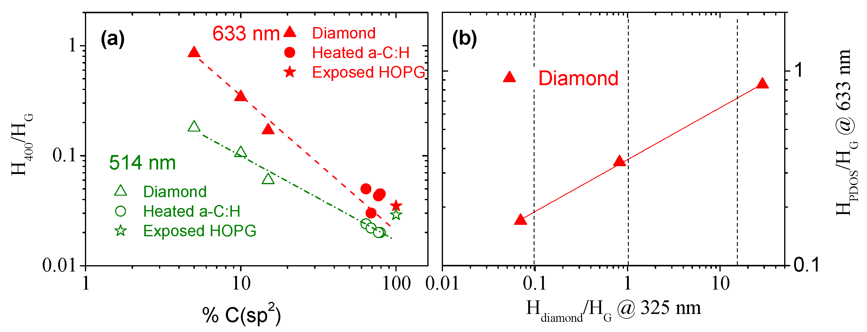
The 400 cm−1 band height of the diamond samples, attributed to graphitic PDOS rising, has been plotted relatively to the G band in Figure 5a as a function of the sp2 content obtained by EELS analysis. The full procedure is described in detail elsewhere [31] and has already been applied successfully to amorphous carbons and to oxidized-graphenic nanoplatelets [31,46]. One can see that for these samples, the less the amount of sp2, the higher this band is, down to 5% of sp2. Plotting of the 633 and 514 nm data reveals that the H400/HG ratio is much more intense using 633 nm excitation laser for lower sp2 contents, and the difference is less pronounced when increasing the amount of sp2 carbons. We also notice that H400/HG data from heated aCH are well in line when extrapolated, for both 633 and 514 nm. Data are difficult to extract with 325 nm and will not be presented here, due to the low signal to noise ratio. For exposed HOPG (put arbitrarily at 100% sp2), for which the band close to 400 cm−1 has been attributed to the double resonance mechanism, the H400/HG ratio is close to the one of heated a-C:H. This may be a coincidence, but the question remains open. In Figure 5b, we have displayed the H400/HG ratio of the different diamond samples D (1%), D (2%) and D (3%) recorded at 633 nm as a function of Hdiamond/HG recorded at 325 nm and show, as a trend, they are correlated. Hdiamond/HG is related to the relative amount of sp3 carbons found in diamond crystallites and can be quantified with standard 633 nm laser. As it does not require UV laser to reveal this diamond band, our correlation could help to estimate the amount of sp3 carbons involved in diamond crystallites by recording a spectrum with a more standard 633 nm laser. This is however qualitative as band heights are obtained after background subtraction, which could introduce error bars if this operation is not well done when backgrounds are very sloppy (see Figure S2b for example). Last comment about the use of this band: One should take care about systematically using its intensity as for sp rich materials, a band was found lying at the same frequency [18].

4. Conclusions

Comparing defective sp2 and sp3 containing samples allowed us to investigate the Raman spectral region between 300 and 900 cm−1. It is usually thought that defects lead to a PDOS rise in that region. We confirm, by using three excitation wavelengths, that for amorphous carbon this is true, with two broad bands lying at 400 and 700 cm−1. For diamonds containing a large amount of sp2 aromatic carbons as well as for heated a-C:H, this is also true but with only one band at 400 cm−1 due to out of plane acoustic phonons at the M point of the Brillouin zone of a graphitic structure. However, for deuterium exposed HOPG, we have shown that bands appearing in this spectral window are not due to PDOS of graphite but are due to the so-called double resonance mechanism leading to D3, D4 and D5 bands, plus their combination mode with D’ close to 1900 cm−1. We evidenced that these bands are one to two orders of magnitude higher in intensity than what they are supposed to be according to the seminal work on graphene by Venezuela et al. [5], but the number of defects and nature of our samples may be very different. This observation could be used in a future work to better characterize the nature and quantity of these defects in defective graphite samples.

Supplementary Materials

The following are available online at https://www.mdpi.com/2311-5629/5/4/79/s1, Figure S1: D and G band dispersion, Figure S2: Multi-wavelength Raman spectra without base line subtraction. Figure S3: EELS spectra of as deposited a-C:H sample, and as-grown diamond film.

Author Contributions

C.P. recorded and interpreted Raman spectra of all the samples. He also obtained amorphous samples. L.L. acquired and analyzed TEM/EELS data under the supervision of R.A.; J.G.B. deposited and analyzed diamond samples. G.C. exposed HOPG samples. All authors contributed to the writing and editing of the manuscript.

Funding

This research received no external funding.

Acknowledgments

CP wants to acknowledge his son and wife for giving him energy to write this manuscript during heatwave time. The TEM and EELS measurements were performed at the Laboratorio de Microscopias Avanzadas (LMA), Instituto de Nanociencia de Aragon (INA), Universidad de Zaragoza (Spain). R.A. gratefully acknowledges the support from the Spanish Ministerio de Economia y Competitividad (MAT2016-79776-P) and from the European Union H2020 program “ESTEEM3” (823717).".

Conflicts of Interest

The authors declare no conflict of interest.

References

  1. Merlen, A.; Buijnsters, J.G.; Pardanaud, C. A Guide to and Review of the Use of Multiwavelength Raman Spectroscopy for Characterizing Defective Aromatic Carbon Solids: From Graphene to Amorphous Carbons. Coatings 2017, 7, 153. [Google Scholar] [CrossRef]
  2. Piscanec, S.; Mauri, F.; Ferrari, A.; Lazzeri, M.; Robertson, J. Ab initio resonant Raman spectra of diamond-like carbons. Diam. Relat. Mater. 2005, 14, 1078–1083. [Google Scholar] [CrossRef]
  3. Reich, S.; Thomsen, C. Raman spectroscopy of graphite. Philos. Trans. R. Soc. Lond. A 2004, 362, 2271–2288. [Google Scholar] [CrossRef] [PubMed]
  4. Prawer, S.; Nemanich, R.J. Raman spectroscopy of diamond and doped diamond. Philos. Trans. R. Soc. A Math. Phys. Eng. Sci. 2004, 362, 2537–2565. [Google Scholar] [CrossRef]
  5. Venezuela, P.; Lazzeri, M.; Mauri, F. Theory of double-resonant Raman spectra in graphene: Intensity and line shape of defect-induced and two-phonon bands. Phys. Rev. B 2011, 84, 035433. [Google Scholar] [CrossRef]
  6. Meunier, V.; Filho, A.G.S.; Barros, E.B.; Dresselhaus, M.S. Physical properties of low-dimensional sp2-based carbon nanostructures. Rev. Mod. Phys. 2016, 88, 025005. [Google Scholar] [CrossRef]
  7. Ferrari, A.C.; Robertson, J. Interpretation of Raman spectra of disordered and amorphous carbon. Phys. Rev. B 2000, 61, 14095. [Google Scholar] [CrossRef]
  8. Ferrari, A.C.; Robertson, J. Resonant Raman spectroscopy of disordered, amorphous, and diamondlike carbon. Phys. Rev. B 2001, 64, 075414. [Google Scholar] [CrossRef]
  9. Ferrari, A.C.; Robertson, J. Raman spectroscopy of amorphous, nanostructured, diamond-like carbon, and nanodiamon. Philos. Trans. R. Soc. Lond. A 2004, 362, 2477. [Google Scholar] [CrossRef]
  10. Kuzmany, H.; Pfeiffer, R.; Salk, N.; Günther, B. The mystery of the 1140 cm−1 Raman line in nanocrystalline diamond films. Carbon 2004, 42, 911–917. [Google Scholar] [CrossRef]
  11. Arenal, R.; Montagnac, G.; Bruno, P.; Gruen, D.M. Multiwavelength Raman spectroscopy of diamond nanowires present in n-type ultrananocrystalline films. Phys. Rev. B 2007, 76, 245316. [Google Scholar] [CrossRef]
  12. Mermoux, M.; Chang, S.; Girard, H.A.; Arnault, J.-C. Raman spectroscopy study of detonation nanodiamond. Diam. Relat. Mater. 2018, 87, 248–260. [Google Scholar] [CrossRef]
  13. Puech, P.; Plewa, J.-M.; Mallet-Ladeira, P.; Monthioux, M. Spatial confinement model applied to phonons in disordered graphene-based carbons. Carbon 2016, 105, 275–281. [Google Scholar] [CrossRef]
  14. Couzi, M.; Bruneel, J.-L.; Talaga, D.; Bokobza, L. A multi wavelength Raman scattering study of defective graphitic carbon materials: The first order Raman spectra revisited. Carbon 2016, 107, 388–394. [Google Scholar] [CrossRef]
  15. Arenal, R.; Liu, A.C.Y. Clustering of aromatic rings in near-frictionless hydrogenated amorphous carbon films probed using multiwavelength Raman spectroscopy. Appl. Phys. Lett. 2007, 91, 211903. [Google Scholar] [CrossRef]
  16. Pardanaud, C.; Martin, C.; Roubin, P.; Giacometti, G.; Hopf, C.; Schwarz-Selinger, T.; Jacob, W. Raman spectroscopy investigation of the H content of heated hard amorphous carbon layers. Diam. Relat. Mater. 2013, 34, 100–104. [Google Scholar] [CrossRef]
  17. Pardanaud, C.; Martin, C.; Cartry, G.; Ahmad, A.; Schiesko, L.; Giacometti, G.; Carrere, M.; Roubin, P. In-plane and out-of-plane defects of graphite bombarded by H, D and He investigated by atomic force and Raman microscopies. J. Raman Spectrosc. 2015, 46, 256–265. [Google Scholar] [CrossRef]
  18. Casari, C.S.; Bassi, A.L.; Baserga, A.; Ravagnan, L.; Piseri, P.; Lenardi, C.; Tommasini, M.; Milani, A.; Fazzi, D.; Bottani, C.E.; et al. Low-frequency modes in the Raman spectrum of sp-sp2 nanostructured carbon. Phys. Rev. B 2008, 77, 195444. [Google Scholar] [CrossRef]
  19. Merkulov, V.I.; Lannin, J.S.; Munro, C.H.; Asher, S.A.; Veerasamy, V.S.; Milne, W.I. uv studies of tetrahedral bonding in diamondlike amorphous carbon. Phys. Rev. Lett. 1997, 78, 4869–4872. [Google Scholar] [CrossRef]
  20. Gilkes, K.W.R.; Prawer, S.; Nugent, K.W.; Robertson, J.; Sands, H.S.; Lifshitz, Y.; Shi, X. Direct quantitative detection of the sp3 bonding in diamond-like carbon films using ultraviolet and visible Raman spectroscopy. J. Appl. Phys. 2000, 87, 7283–7289. [Google Scholar] [CrossRef]
  21. Chen, Z.Y.; Zhao, J.P.; Yano, T.; Ooie, T.; Yoneda, M.; Sakakibara, J. Observation of sp3 bonding in tetrahedral amorphous carbon using visible Raman spectroscopy. J. Appl. Phys. 2000, 88, 2305–2308. [Google Scholar] [CrossRef]
  22. Bosak, A.; Krisch, M. Phonon density of states probed by inelastic X-ray scattering. Phys. Rev. B 2005, 72, 224305. [Google Scholar] [CrossRef]
  23. Wirtz, L.; Rubio, A. The phonon dispersion of graphite revisited. Solid State Commun. 2004, 131, 141–152. [Google Scholar] [CrossRef]
  24. Kumagai, T.; Choi, J.; Izumi, S.; Kato, T. Structures and phonon properties of nanoscale fractional graphitic structures in amorphous carbon determined by molecular simulations. J. Appl. Phys. 2010, 107, 104307. [Google Scholar] [CrossRef]
  25. Dmitriev, S.V.; Baimova, J.A.; Savin, A.V.; Kivshar, Y.S. Ultimate strength, ripples, sound velocities, and density of phonon states of strained graphene. Comput. Mater. Sci. 2012, 53, 194–203. [Google Scholar] [CrossRef]
  26. Cong, X.; Li, Q.-Q.; Zhang, X.; Lin, M.-L.; Wu, J.-B.; Liu, X.-L.; Venezuela, P.; Tan, P.-H. Probing the acoustic phonon dispersion and sound velocity of graphene by Raman spectroscopy. Carbon 2019, 149, 19–24. [Google Scholar] [CrossRef]
  27. Si, C.; Sun, Z.; Liu, F. Strain engineering of graphene: A review. Nanoscale 2016, 8, 3207–3217. [Google Scholar] [CrossRef]
  28. Li, Y.; Li, Z.; Shen, P.K. Simultaneous Formation of Ultrahigh Surface Area and Three-Dimensional Hierarchical Porous Graphene-Like Networks for Fast and Highly Stable Supercapacitors. Adv. Mater. 2013, 25, 2474–2480. [Google Scholar] [CrossRef]
  29. Baig, N.; Saleh, T.A. Electrodes modified with 3D graphene composites: A review on methods for preparation, properties and sensing applications. Microchim. Acta 2018, 185, 283. [Google Scholar] [CrossRef]
  30. Ferrari, A.C.; Bassi, A.L.; Tanner, B.K.; Stolojan, V.; Yuan, J.; Brown, L.M.; Rodil, S.E.; Kleinsorge, B.; Robertson, J. Density, sp3fraction, and cross-sectional structure of amorphous carbon films determined by X-ray reflectivity and electron energy-loss spectroscopy. Phys. Rev. B 2000, 62, 11089–11103. [Google Scholar] [CrossRef]
  31. Lajaunie, L.; Pardanaud, C.; Martin, C.; Puech, P.; Hu, C.; Biggs, M.; Arenal, R. Advanced spectroscopic analyses on a:C-H materials: Revisiting the EELS characterization and its coupling with multi-wavelength Raman spectroscopy. Carbon 2017, 112, 149–161. [Google Scholar] [CrossRef] [Green Version]
  32. Buijnsters, J.; Vázquez, L.; Ter Meulen, J. Substrate pre-treatment by ultrasonication with diamond powder mixtures for nucleation enhancement in diamond film growth. Diam. Relat. Mater. 2009, 18, 1239–1246. [Google Scholar] [CrossRef]
  33. Hopf, C.; Von Keudell, A.; Jacob, W. The influence of hydrogen ion bombardment on plasma-assisted hydrocarbon film growth. Diam. Relat. Mater. 2003, 12, 85–89. [Google Scholar] [CrossRef]
  34. Hopf, C.; Angot, T.; Aréou, E.; Dürbeck, T.; Jacob, W.; Martin, C.; Pardanaud, C.; Roubin, P.; Schwarz-Selinger, T. Characterization of temperature-induced changes in amorphous hydrogenated carbon thin films. Diam. Relat. Mater. 2013, 37, 97–103. [Google Scholar] [CrossRef] [Green Version]
  35. Ahmad, A.; Dubois, J.; Pasquet, T.; Carrere, M.; Layet, J.M.; Faure, J.B.; Cartry, G.; Kumar, P.; Minea, T.; Mochalskyy, S.; et al. Negative-ion surface production in hydrogen plasmas: Modeling of negative-ion energy distribution functions and comparison with experiments. Plasma Sources Sci. Technol. 2013, 22, 25006. [Google Scholar] [CrossRef] [Green Version]
  36. Schiesko, L.; Carrere, M.; Cartry, G.; Layet, J.M. H—Production on a graphite surface in a hydrogen plasma. Plasma Sources Sci. Technol. 2008, 17, 35023. [Google Scholar] [CrossRef]
  37. Buijnsters, J.G.; Vázquez, L. Growth Dynamics of Nanocrystalline Diamond Thin Films Deposited by Hot Filament Chemical Vapor Deposition: Influence of Low Sticking and Renucleation Processes. J. Phys. Chem. C 2011, 115, 9681–9691. [Google Scholar] [CrossRef]
  38. Castro, M.; Cuerno, R.; Nicoli, M.; Vazquez, L.; Buijnsters, J.G. Universality of cauliflower-like fronts: From nanoscale thin films to macroscopic plants. N. J. Phys. 2012, 14, 103039. [Google Scholar] [CrossRef] [Green Version]
  39. Pardanaud, C.; Martin, C.; Roubin, P. Multiwavelength Raman spectroscopy analysis of a large sampling of disordered carbons extracted from the Tore Supra tokamak. Vib. Spectrosc. 2014, 70, 187–192. [Google Scholar] [CrossRef] [Green Version]
  40. Popov, M.; Churkin, V.; Kirichenko, A.; Denisov, V.; Ovsyannikov, D.; Kulnitskiy, B.; Perezhogin, I.; Aksenenkov, V.; Blank, V. Raman Spectra and Bulk Modulus of Nanodiamond in a Size Interval of 2–5 nm. Nanoscale Res. Lett. 2017, 12, 561. [Google Scholar] [CrossRef] [Green Version]
  41. Pardanaud, C.; Aréou, E.; Martin, C.; Ruffe, R.; Angot, T.; Roubin, P.; Hopf, C.; Schwarz-Selinger, T.; Jacob, W. Raman micro-spectroscopy as a tool to measure the absorption coefficient and the erosion rate of hydrogenated amorphous carbon films heat-treated under hydrogen bombardment. Diam. Relat. Mater. 2012, 22, 92–95. [Google Scholar] [CrossRef] [Green Version]
  42. Pardanaud, C.; Martin, C.; Giacometti, G.; Mellet, N.; Pégourié, B.; Roubin, P. Thermal stability and long term hydrogen/deuterium release from soft to hard amorphous carbon layers analyzed using in-situ Raman spectroscopy. Comparison with Tore Supra deposits. Thin Solid Films 2015, 581, 92–98. [Google Scholar] [CrossRef] [Green Version]
  43. Levshov, D.; Than, T.X.; Arenal, R.; Popov, V.N.; Parret, R.; Paillet, M.; Jourdain, V.; Zahab, A.A.; Michel, T.; Yuzyuk, Y.I.; et al. Experimental Evidence of a Mechanical Coupling between Layers in an Individual Double-Walled Carbon Nanotube. Nano Lett. 2011, 11, 4800–4804. [Google Scholar] [CrossRef]
  44. Picher, M.; Anglaret, E.; Arenal, R.; Jourdain, V. Processes Controlling the Diameter Distribution of Single-Walled Carbon Nanotubes during Catalytic Chemical Vapor Deposition. ACS Nano 2011, 5, 2118–2125. [Google Scholar] [CrossRef]
  45. Arenal, R.; Ferrari, A.C.; Reich, S.; Wirtz, L.; Mevellec, J.-Y.; Lefrant, S.; Rubio, A.; Loiseau, A. Raman Spectroscopy of Single-Wall Boron Nitride Nanotubes. Nano Lett. 2006, 6, 1812–1816. [Google Scholar] [CrossRef]
  46. Gross, K.; Barragán, J.J.P.; Sangiao, S.; De Teresa, J.M.; Lajaunie, L.; Arenal, R.; Calderón, H.A.; Prieto, P. Electrical conductivity of oxidized-graphenic nanoplatelets obtained from bamboo: Effect of the oxygen content. Nanotechnology 2016, 27, 365708. [Google Scholar] [CrossRef] [Green Version]
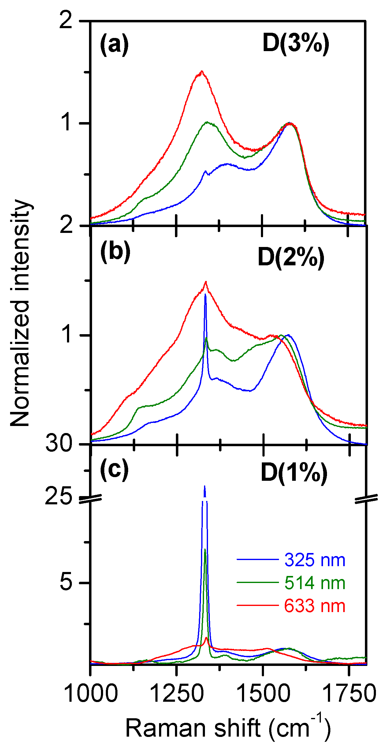
Figure 1. Diamond multi-wavelength Raman spectra (325, 514 and 633 nm). Methane content during CVD diamond growth was varied from 3% down to 1% from (ac), respectively.
Carbon 05 00079 g001
Figure 2. Multi-wavelength Raman spectra (325, 514 and 633 nm, same color code as in Figure 1) of a-C:H post heated at 500 °C. Isothermal heating time is varied from 0 min up to 1000 min from (ad), respectively. A base line has been subtracted. Non-modified Raman spectra are given for 514 nm wavelength in Figure S2 (see Supporting Information). Blue, green and red lines are for 325, 514 and 633 nm lasers, respectively.
Carbon 05 00079 g002
Figure 3. Multi-wavelength Raman spectra of deuterium implanted HOPG for wavelengths of (a) 633 nm, (b) 514 nm, and (c) 325 nm. The indicated OPD and IPD components are, respectively, the out of plane and in plane defects evidenced in [17].
Carbon 05 00079 g003
Figure 4. PDOS spectral region (300–900 cm−1) for diamond, a-C:H post heated at 500 °C, a-C (taken from [24] and [42]) and deuterium implanted HOPG. (a) PDOS references (see text for details). Experimental data for (b) 514 nm and (c) 633 nm wavelength excitation. The sharp band at 520 cm−1 is due to the underlying silicon wafer. (df) zoom of the low intensity modes for exposed HOPG probed with 633, 514 and 325 nm, respectively. Note that the 2D band (near 2700 cm−1) coming from the underlying unmodified HOPG can be seen, as the ion implantation depth is lower than the laser photon penetration depth. The spectral data in (df) corresponding to the HOPG implanted with 400 eV deuterium ions have been rescaled for better visualization.
Carbon 05 00079 g004
Figure 5. 400 cm−1 intensity variation with sp2/sp3 content. (a) H400/HG as function of sp2 content determined by EELS. (b) H400/HG recorded at 633 nm as function of Hdiamond/HG recorded at 325 nm.
Carbon 05 00079 g005