Article

Electrodeposition of Cu–SWCNT Composites

1
Department of Chemistry, Rice University, Houston, TX 77005, USA
2
Energy Safety Research Institute, Swansea University, Bay Campus, Swansea SA1 8EN, UK
3
Shared Equipment Authority, Rice University, Houston, TX 77005, USA
4
Department of Materials Science and Nanoengineering, Rice University, Houston, TX 77005, USA
*
Author to whom correspondence should be addressed.
Submission received: 23 May 2019 / Revised: 25 June 2019 / Accepted: 11 July 2019 / Published: 13 July 2019

Abstract

:
Single walled carbon nanotubes (SWCNTs) are used as a component of a plating solution of CuSO4 for direct current electrodeposition of Cu–SWCNT composites with varying nanotube proportions without the use of either a surfactant, a dispersing agent, or functionalization of the SWCNTs. The Cu–SWCNT composites are characterized by scanning electron microscopy (SEM), energy dispersive X-ray analysis (EDX), X-ray photoelectron spectroscopy (XPS), X-ray diffraction (XRD), and Raman spectroscopy. The composites are comprised of metallic Cu and SWCNTs with minor oxide impurities, as well as the residual (Fe) catalyst from the unpurified SWCNTs, in addition to displaying nanotube-mediated morphological differences. EDX analysis of carbon (wt%) is close to quantitative with respect to the wt% of SWCNTs added to the electrolysis solution. The presence of SWCNTs decreases the oxidation of the copper, as well as changing the identity of the oxide from CuO, for electrolysis of Cu, to Cu2O. Hard adherent Cu–SWCNT coatings are prepared by the addition of Cu powder to the electrolysis solution. The approach described in this paper will enable controlled synthesis of metal-nanomaterial composites that can potentially be processed further into high ampacity electrical conductors.

Graphical Abstract

1. Introduction

The potential of carbon nanotubes (CNTs), especially single walled carbon nanotubes (SWCNTs), for high-ampacity, low weight, electrically conducting cables, as a replacement to traditional copper wires, has garnered significant research attention [1]. Unfortunately, despite much hype, the realization of CNT-based transmission cables has to overcome significant technical hurdles. One stopgap solution involves the admixing of small amounts of CNTs to enhance the electrical properties of copper [2,3,4,5]. The fabrication of such Cu–CNT composite material, termed “ultra-conductive copper”, can be achieved by a variety of different methods, including electrolytic co-deposition [6,7], electroless plating [8,9], and powder metallurgy [10]. Being malleable, copper offers an excellent composite matrix, which can be processed into a desired shape, with potential orientation of the fillers, through extrusion, densification, and hot-pressing. Thus, routes to prepare precursor composites with a controlled Cu–CNT composition could provide potential precursors to extruded wires.
Prior studies have evaluated electrodeposition of copper–carbon material composites under various experimental conditions. One of the challenges pertains to improving the interface between copper and the highly hydrophobic surface of carbon substrates [11]. Arai et al. have reported the fabrication and characterization of Cu–CNT composite films using an electrodeposition technique [12,13]. In particular, they have reported the synthesis of copper–multiwalled carbon nanofiber and multi walled carbon nanotube (MWCNT) composite powder materials [7,14]. Such studies give impetus to progress further in terms of obtaining a deeper understanding of the interface between copper and carbon nanotubes. In this regard the electrodeposition of copper single walled carbon nanotube (SWCNT) coatings in an ultrasonic field [15], and the synthesis of Cu–MWCNT and Cu–SWCNT composite films via electrodeposition where a dispersing agent was used to homogenize the hydrophobic CNTs have been reported [16,17]. Fen et al. have reported the use of nano diamond as dispersing/seed agents [18]. However, there is a paucity of studies focused on Cu–SWCNT composite formation in electroplating bath conditions free of dispersing agents, which will likely contribute to contamination of the resulting composites and will be hard to eliminate.
We have previously reported the electromigration behavior of raw and acid purified SWCNTs in dilute aqueous systems, in the absence of surfactant, with the addition of either acetic acid or CuSO4 [19]. The results showed that the electromigration of raw SWCNTs (with catalyst residue) in the presence of CuSO4 resulted in the formation of a Cu–SWCNT composite material at the cathode. In contrast, acid purified SWCNTs were observed to diffuse to the anode, creating fibrils agglomerates [19]. With the addition of CuSO4 the direction of electromigration reversed back towards the cathode resulting in the co-deposition of SWCNTs and Cu metal on the cathode. In this study, we report the effects of reaction conditions and varying the proportion of added SWCNTs studied in relation to characteristic properties of the related composites in terms of morphology and composition. The electroplating process (using two electrodes) was kept the same as in our prior paper on electromigration [19] for the sake of simplicity and consistency, and keeping practical applications in mind. Further experiments utilizing reference electrodes are reported elsewhere [20]. A control study based on admixing copper microparticles into the electroplating bath and the resulting composite morphologies will also be presented in this report.

2. Materials and Methods

Commercial grade copper (16 or 18 gauge) and platinum (18 gauge) wire (Sigma Aldrich, St Louis, MO, USA) were cleaned by wiping their surfaces with acetone, to remove any loosely bound or dissolvable surface impurities. Unpurified raw HiPCO SWCNTs (SWCNTs) were obtained from Tubes@Rice (Houston, TX, USA) batch 09-HiPco-0093 (batch No. 188.4) and used without further purification. Aqueous acetic acid (0.8 M) was used as supplied. CuSO4.5H2O, concentrated sulfuric acid, acetone, and ethanol were obtained from Fisher Scientific (St. Louis, MO, USA) and used as is.
The electroplating bath was comprised of 0.1 M copper sulfate solution fortified with 5% by volume dilute acetic acid solution (0.8 M) to improve the bath’s electrical conductivity. Raw CNTs were added to the 0.1 M CuSO4 baths (with 5% 0.8 M acetic acid added) and sonicated for 10 min before commencement of the electroplating reactions. The plating baths were initially heated to 60 °C over 10 min with 700 rpm stirring in the case of CNT-containing baths. No stirring was conducted for CNT-free control. Then heat was turned off after 10 min of reaction, as the bath heated up due to the externally supplied current, and the reactions were continued without further heating. The anode was a 1.25 cm section of 18-gauge platinum wire (Sigma Aldrich, St Louis, MO, USA) and the cathode was a 5 cm section of 18-gauge copper wire (Sigma). All baths were subjected to 14.7 V DC (Elenco Precision Inc. (Wheeling, IL, USA) Model XP-85 variable DC power supply) during the electroplating reaction. No surfactants were used. The Cu–CNT composite was deposited on the copper cathode and sloughed off the cathode frequently. After the reactions, the deposit from each sample was collected on 0.2 μm polyvinylidene difluoride (PVDF) membranes (Millipore), washed thoroughly in DI water, followed by acetone (to remove water), and air-dried over 3 days to obtain porous, powdery deposits. The samples were weighed and saved for characterization. Table 1 summarizes the reaction conditions used to obtain the various Cu–SWCNT electroplated samples (and SWCNT-free control).
Visual evidence for SWCNT entrapment in copper-based composite matrix was obtained by the dispersion of 230 mg of the sample with 2.3% SWCNTs, in a mixture of concentrated H2SO4 (3 mL) and DI water (5 mL) heated to 200 °C for 1 h with 350 rpm stirring. The sulfuric acid was added to dissolve some of the copper and release embedded CNT aggregates. The dispersion was allowed to cool and the particles were allowed to settle overnight. The association of the black aggregates with the magnetic stir bar visually indicated the presence of the SWCNTs incorporating iron catalyst impurities (Figure S1).
In a parallel experiment, micron-sized copper powder (3.2 g, Sigma, St. Louis, MO, USA) was added to 0.1 M CuSO4 (400 mL) in a 500-mL plating bath incorporating acetic acid (5 mL), with SWCNTs (17 mg, 0.004 wt%), to yield a combination of hard coatings on four 10 cm copper cathodes. The bath was sonicated 20 min before commencement of the electroplating reaction. The bath was stirred at all times at 1000–1200 rpm to facilitate thorough mixing of dispersed fillers in the bath, and the reaction was allowed to proceed for 8.5 h. Temperature was maintained at 70 °C. Care was taken to ensure that the cathode and anode (1.25 cm platinum wire electrode, Sigma Aldrich, St Louis, MO, USA) were fully immersed at the periphery of the mixing vortex in the bath. If needed, DI water was added to the bath to sustain plating bath volume at the starting level, to account for water evaporation during the plating process. After the reaction, the copper wire cathode with hardened copper/composite coating was thoroughly washed under running DI water before being further washed in ethanol or acetone (to accelerate the sample drying process) and air-dried overnight. In addition, sludge was collected from the bath and washed over a 0.2 μm PVDF filter membrane (Millipore) using copious amounts of water followed by acetone or ethanol to quickly dry out moisture. The filter cake was air-dried overnight and subsequently stored in closed containers. The coated copper wires were stored in Ziploc bags for further characterization, alongside corresponding powdery dried deposit obtained on the filter membrane. The fraction of SWCNTs in the composite material was estimated approximately by assuming that SWCNTs had distributed themselves proportionally between the hard coatings, and the powdery deposit.
All raw materials and composite samples were characterized using a variety of material characterization techniques to obtain a detailed understanding of their composition and morphology. X-ray photoelectron spectroscopy (XPS) measurements were obtained over a 700 μm × 300 μm sample area using a Kratos Axis Supra system with an Al-Kα X-ray source (1486.7 eV) operated at emission current 15.00 mA and pass energy 20 eV, with charge neutralization applied to each sample using a filament bias of 1 V, filament current 0.4 A and charge balance 3.3 V. Spectra were recorded using a dwell time of 250 ms over a single sweep. Data was analyzed with CasaXPS software (Version 2.3.12.8). A spectrum energy calibration was performed with respect to the C 1s peak with binding energy set to 284.8 eV (NIST XPS database). The speciation and composition variation were obtained by recording the multiplex spectra for C 1s, O 1s, and Cu 2p elemental energy levels. X-ray diffraction (XRD) measurements were conducted on a Rigaku D/MAX 2100 diffractometer with Cu-Kα radiation and a graphite monochromator. Zero-background sample holders made of (511) Silicon single crystal wafers were used for all samples. Data analysis was performed using Rigaku PDXL2 data analysis software. The amount of Cu (PDF 04-009-2090), Cu2O (PDF 04-002-3214) or CuO (PDF 04-007-1375) in the samples was determined by Rietveld refinement of the measured XRD patterns. Scanning electron microscopy (SEM) was carried out using a FEI Quanta 400 ESEM FEG equipped with an EDS detector (FEI, Hillsboro, OR, USA). Images were acquired by placing samples on double-sided carbon tape that is fixed to aluminum SEM stubs, used as received. Images were acquired with a typical operating voltage of 20 kV, with a working distance of 10 mm, spot size 3, under high vacuum. Energy dispersive X-ray (EDX) analysis was performed and analyzed using EDAX TEAM™ software using 3 sample areas. Thermogravimetric analyses (TGA) were conducted using a TA instruments (New Castle, DE, USA) Q-600 simultaneous TGA/DSC with air as a carrier medium. Samples (5–10 mg) were then placed in alumina pans and heated with a ramp rate of 3 °C/min under 70 mL/min of the carrier gas. Raman spectra were obtained using Renishaw inVia Raman Microscope (Wotton-under-Edge, UK), at 514.5 nm wavelength, using a 50× LWD lens, data was acquired with 3 or more accumulations between 100 cm−1 and 3300 cm−1 with cosmic-ray background removal applied.

3. Results and Discussion

SEM analysis of the raw HiPCO SWCNTs indicates a highly bundled fibrous structure. The associated EDX data indicates iron catalyst impurity of ~47 wt%, while TGA data coupled with EDX analysis of the residue revealed a ~20 wt% iron impurity [21]. This discrepancy is due to local variations of iron content in the sample [22]. SEM analysis of the copper wire cathode showed scratches due to handling, while EDX surprisingly revealed ~4 wt% iron content by weight probably due to native impurities, since the material was commercial grade.

3.1. Electrolysis of SWCNTs in CuSO4 Solution

Several copper composite formulations bearing a range of calculated SWCNT percentages were prepared using the electroplating method by varying the SWCNT concentration in the electroplating bath, while maintaining a [CuSO4] of 0.1 M. Based upon our previous work it is likely that a fraction of the copper ions from the bath were complexed to the SWCNT [9,19], forming nuclei for growth of electroplated copper grains among the bundles [23]. Prior studies have reported on the benefits of seeding copper moieties among SWCNT aggregates via chemical deposition methods, especially via organic media that exfoliate nanomaterial aggregates to promote improved adhesion of electroplated copper coatings on CNT surfaces [3]. Vortexing in the bath, caused by rapid stirring, and the applied potential difference between the electrodes likely caused migration of copper ions along with SWCNT aggregates (and their metallic catalyst impurities) toward the cathode. This was also observed in our prior study on electromigration [19].
The mixed deposit of copper and SWCNT grew as a layer on the surface of the copper cathode until it visually reached a thickness of 2–3 mm, at which point it sloughed off and fell to the bottom of the bath. This process was repeated for the durations stated in Table 1 for each sample. The contents of the plating bath, and any remaining deposit adhering loosely to the copper cathode were collected, washed in DI water and acetone, and air-dried (Figure S4). This deposit could be easily removed from the electrode surface, washed with DI water and acetone, and dried for further characterization. Literature reports that higher voltages can speed up electrochemical reactions [24]. Hence, the choice of 14.7 V, which was the highest setting in the DC voltage apparatus used for the study. The enhanced rate of reaction coupled with agitation used to disperse the hydrophobic nanotubes in the plating bath also likely resulted in non-adherent coatings on the cathode, but this was not of major concern as the intention was to first collect any cathodic deposits for subsequent analysis and processing. The cathodic sludge can be collected and processed further into compacts through compression and/or extrusion. Ongoing experiments in our group are attempting to optimize the electroplating process wherein copper is deposited as a smooth layer onto the CNT fiber/cable surfaces directly, rather than onto individual CNT bundles dispersed in the plating bath. Several approaches to preparing copper–nanotube composites are possible and the approach outlined in this paper is one of them, with the uniqueness centered on the avoidance of surfactants despite the fact that the nanotubes are hydrophobic.
Figure 1 shows representative SEM images (at two magnifications) of Cu–SCWNT composites containing varying proportions of SWCNTs produced by direct current electroplating using the chosen constant voltage (14 V) power supply. Based on calculations, composites containing 0, 2.3, 3.8, and 6.2% SWCNTs were obtained. In the absence of SWCNTs (Figure 1a) the Cu deposited as a dendritic (“fern-like”) structure comprising of individual crystallites of 0.25–0.5 μm in size (Figure 1b). A similar morphology has been observed previously for Cu electrolysis under conditions of high concentration and high overpotential [25].
With the addition of 2.3 wt% SWCNTs to the electrolysis solution, the dendritic nature appeared to visually decline while the structure became more porous (Figure 1c). At this concentration the SWCNT bundles appear to be coating the Cu crystallites in a highly heterogeneous manner (Figure 1d). The approach postulated previously, where CNT aggregates are first exfoliated in an organic medium followed by reacting with copper species, can potentially be used to overcome the problem of heterogeneous nature of Cu–CNT composites [3]. Further increasing the SWCNT concentration results in the complete loss of the dendritic structure (Figure 1e,g), and the resulting material is heterogeneous but uniform mix of Cu particles and SWCNTs (Figure 1f). Finally, at the highest concentrations studied herein, the individual Cu crystallites have SWCNTs encapsulating them (Figure 1h). A similar morphology was observed in the electrodeposition of Cu and surfactant dispersed MWCNTs [26,27]. Irrespectively, it is clear that the SWCNTs have altered the nucleation of copper particles during the electroplating process. Unfortunately, as in previous work, it is clear that without subsequent densification the resulting composites will remain heterogeneous [27].
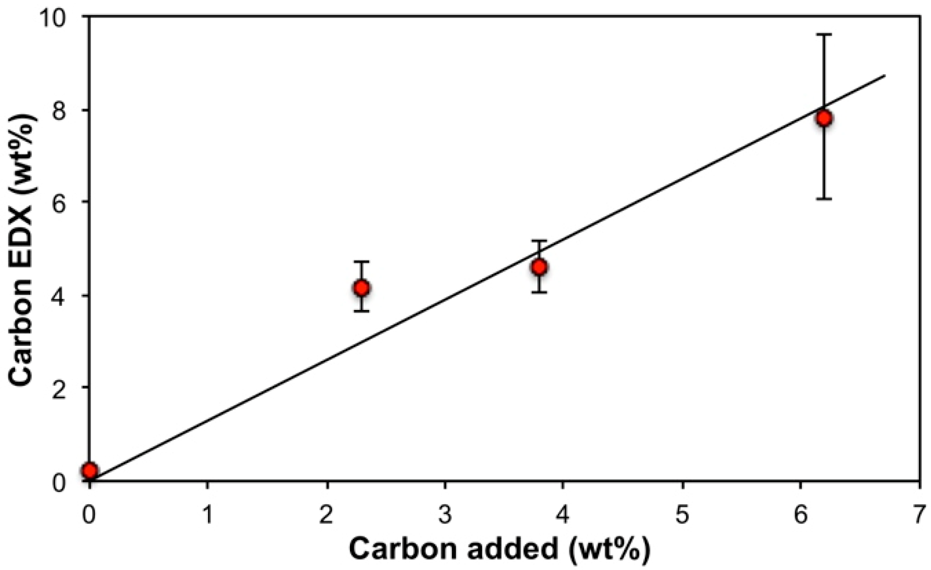
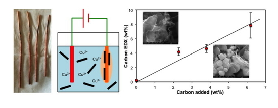
The EDX elemental analysis of the Cu–SWCNT composites is shown in Table 2. Table 2 is intended to show a trend in terms of carbon content for the sake of discussion only, and not to present a statistically validated observation. As would be expected the copper composition is inversely proportional to carbon content (Figure S5), and the EDX analysis of carbon (wt%) is close to quantitative with respect to the wt% of SWCNTs added (Figure 2) suggesting that all the SWCNTs are incorporated into the composite. This is possible considering that all dispersed solids (including any CNTs unbound to the copper during the plating process) in the plating bath were collected (after physical mixing) onto a filter membrane and dried. The presence of oxygen can be due to native oxide layers on the copper formed by self-passivation, along with oxygen-containing defect groups on nanotube surfaces [28]. It is also likely that copper oxides may have formed in the plating bath prior to deposition in the cathode, and prior researchers have reported on the electrodeposition of copper oxides [29,30]. It is interesting to note, however, that the oxygen content decreases dramatically with addition of SWCNT (Table 2), suggesting that the presence of the hydrophobic SWCNTs decreases the oxidation of Cu (see below). However, increased SWCNT content beyond 2.3 wt% did not result in further decrease in oxygen content. The observed trends could likely be due to passivation [31,32], increased corrosion potential [33], or reduction [20] of the Cu; however, we note that under non-electolysis conditions CuO is the preferred composition when copper is deposited on CNTs [34].
The presence of Fe is associated with the catalyst residue present in the SWCNTs [22,35], and hence the iron content is generally proportional to carbon (Figure S6). Surprisingly, even the SWCNT-free control copper deposit was found to contain iron. EDX characterization of copper wire electrode material confirmed the presence of up to 4 wt% of iron. It is likely that some of this iron could have leached into the deposit during the electroplating process.
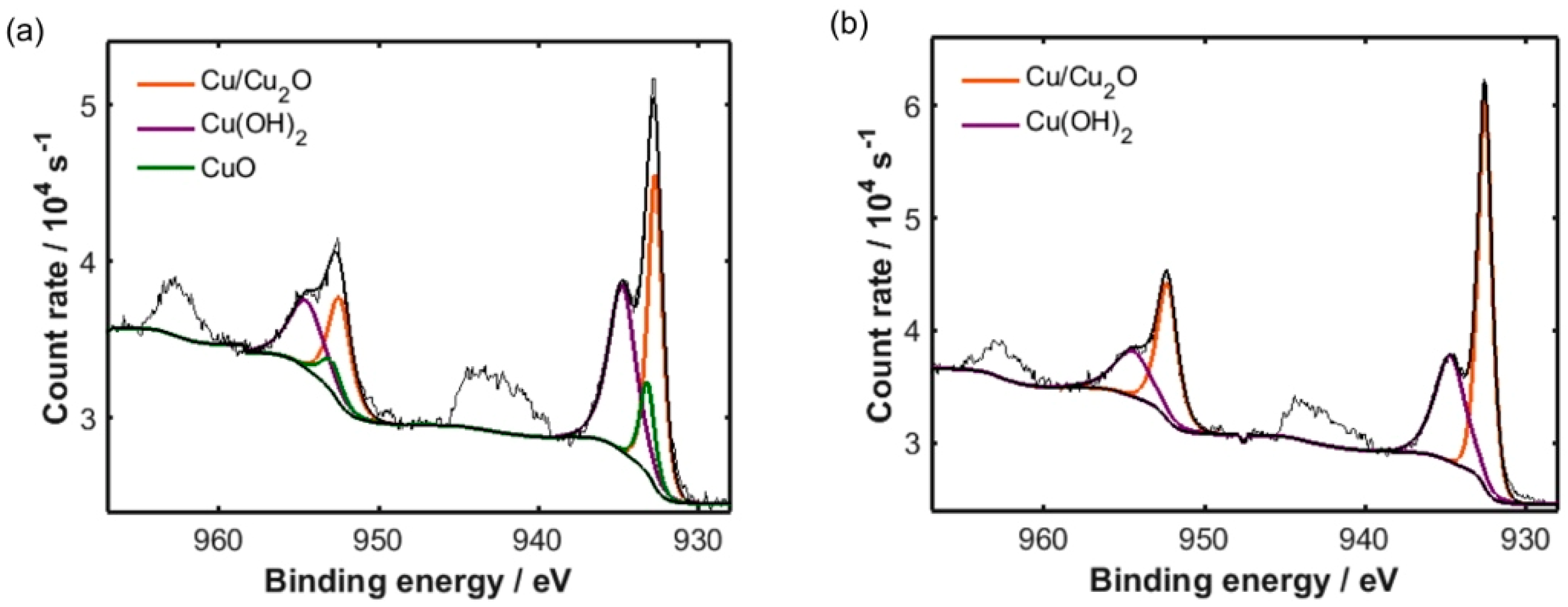
The surface composition of the composites may be verified by XPS analysis (Table 3); Cu 2p spectra corresponding to electrodeposited copper and Cu–SWCNT composite deposited with 4 wt% SWCNTs are displayed in Figure 3a,b, respectively. Whilst it is difficult to separate the contributions from Cu2O and metallic Cu due to the close proximity of their components, each of which appear at a binding energy of ca. 932.7 eV, the presence of a component at ca. 933.2 eV in Figure 3a is consistent with the CuO chemical environment [36,37,38]. Conversely, no CuO component was observed in the case of the Cu–SWCNT composite, indicating that co-deposition with SWCNTs yielded a higher degree of copper reduction than electrodeposition of copper alone. Our hypothesizes is that the possible inhibition of oxidation of copper in the presence of the SWCNTs due to their acting as potential reducing agents or redox catalysts [39,40]. The presence of hydroxides in the samples was likely due to the partial reaction of copper oxide with water from either the bath, or from atmospheric humidity. In both cases, a large component measured at a binding energy of ca. 934.7 eV may be attributed to the presence of Cu(OH)2 in the samples [36,38]. It should be noted that due to small chemical shifts between the Cu/Cu2O and CuO environments, it is difficult to accurately determine the position and relative area of the CuO component in Figure 3a; for this reason, the estimated atomic percentage of CuO given in Table 3 should be treated as approximate.
X-ray diffraction (XRD) of all the electroplated samples (Table 4) reveals crystalline Cu as the major component in all cases. As is suggested by EDX and XPS there is a minor component of oxide in each sample; however, the percentage of oxide was not proportional to percentage of SWCNT added (consistent with EDX measurements, see Table 2), it is possibly due changes in the morphology (Figure 1) and hence surface area of the samples. Alternatively, Liu et al. have shown that during electrodeposition, the thicker the copper plated layer, the thicker was the oxide film [41]. An alternative explanation would be that the presence of SWCNTs alters the plating current density, that is known to affect the concentrations of impurities [42]. We note that unlike XPS (Figure 3) no Cu(OH)2 is observed in the XRD (Figure 4) [43]; however, given the surface nature of XPS, this would suggest that the Cu(OH)2 is formed by surface hydrolysis rather than as a bulk material.
The most interesting observation is that, as suggested by XPS, the identity of the oxide is dependent on the presence of the SWCNTs. The SWCNT-free control displayed the presence of CuO (ICDD #04-007-1375), but the oxide in all the samples containing SWCNTs is Cu2O (ICDD #04-002-3214), see Figure 4. This change suggests that the presence of added SWCNTs modifies the nature of the native oxide layers formed. Additives such as water and acids promote the rate of formation of Cu2O by the oxidation of Cu metal, as well as the further oxidation to CuO. So presumably, under the present conditions the SWCNTs inhibit the subsequent conversion of Cu2O to CuO; however, we have previously observed the opposite under higher energy conditions [34]. An alternative explanation could involve the thickness of the Cu coating.
It was observed previously [42] that when Cu coating is less than 0.165 μm the oxide is CuO (with a Cu2O interface to Cu); however, when the coating is thicker than 0.165 μm the oxide is Cu2O. Based upon this observation, it would suggest that the presence of the SWCNTs acts as a seed for Cu growth. Seeding usually occurs at native or induced defect sites on the nanotube surfaces [44,45]. The crystal grain size for the Cu and the oxides showed no correlation between crystallite size and SWCNT content (Table 4).
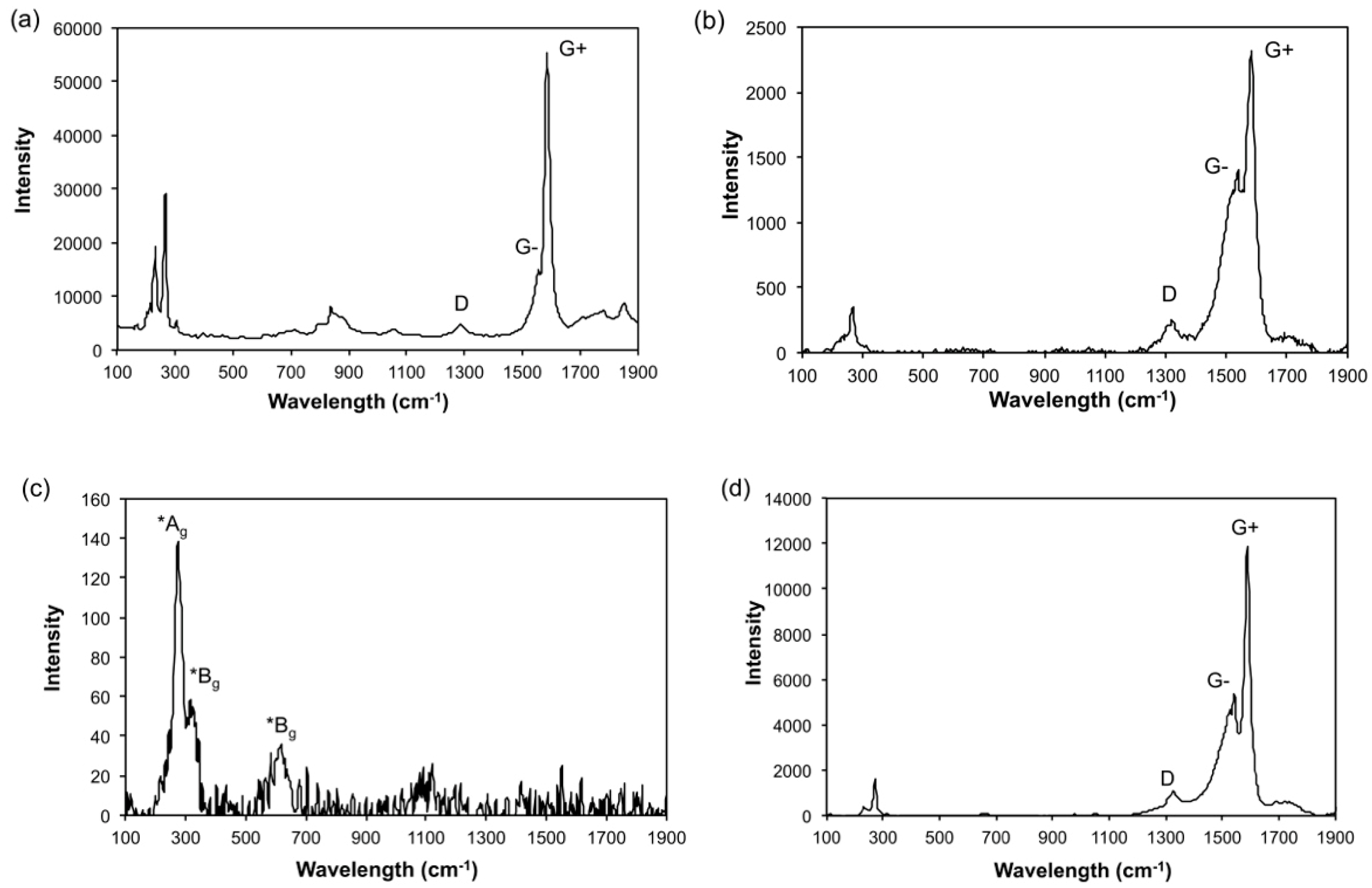
The Raman spectra of the Cu–SWCNTs composites show the presence D and G bands and the radial breathing modes associated with SWCNTs (e.g., Figure 5a). The D band represents the presence of sp3 carbon centers (as opposed to sp2 carbon of a pristine SWCNT), thus, the IG:ID ratio is often used as a good indicator of quality in bulk samples [46]. As seen in Table 5, the IG:ID ratios appeared consistent in the samples containing added SWCNTs, but were lower than for the SWCNTs before electrolysis (IG:ID = 15.52 ± 1.52, Figure 5b). This observation suggests that the structure of the SWCNTs underwent a consistent change during the electroplating process, possibly due to the presence of acetic acid in the plating bath. Prior research has suggested that nanotubes with low diameters and initial IG:ID > 1 are significantly susceptible to structural modification during acid treatment [47].

3.2. Electrolysis in the Presence of Cu Micropowder

The Cu–SWCNT composites generated consisted of porous deposit that sloughed off the cathode into the bath, and had to be filtered, washed, and dried, yielding a powdery residue. In an attempt to induce harder, adherent coatings on the cathode surface, microscale copper particles were suspended in the bath in addition to SWCNTs. Addition of such metal particles has been found to promote the formation of hard coatings through a combination of mechanisms: impact adhesion on electrode surface, followed by nucleation of electroplated coatings on the surfaces of the impacted particles, cementing them onto the electrode surface [48,49]. Hence the addition of Cu powder (<425 μm) was investigated in an attempt to create denser, more adherent coatings.
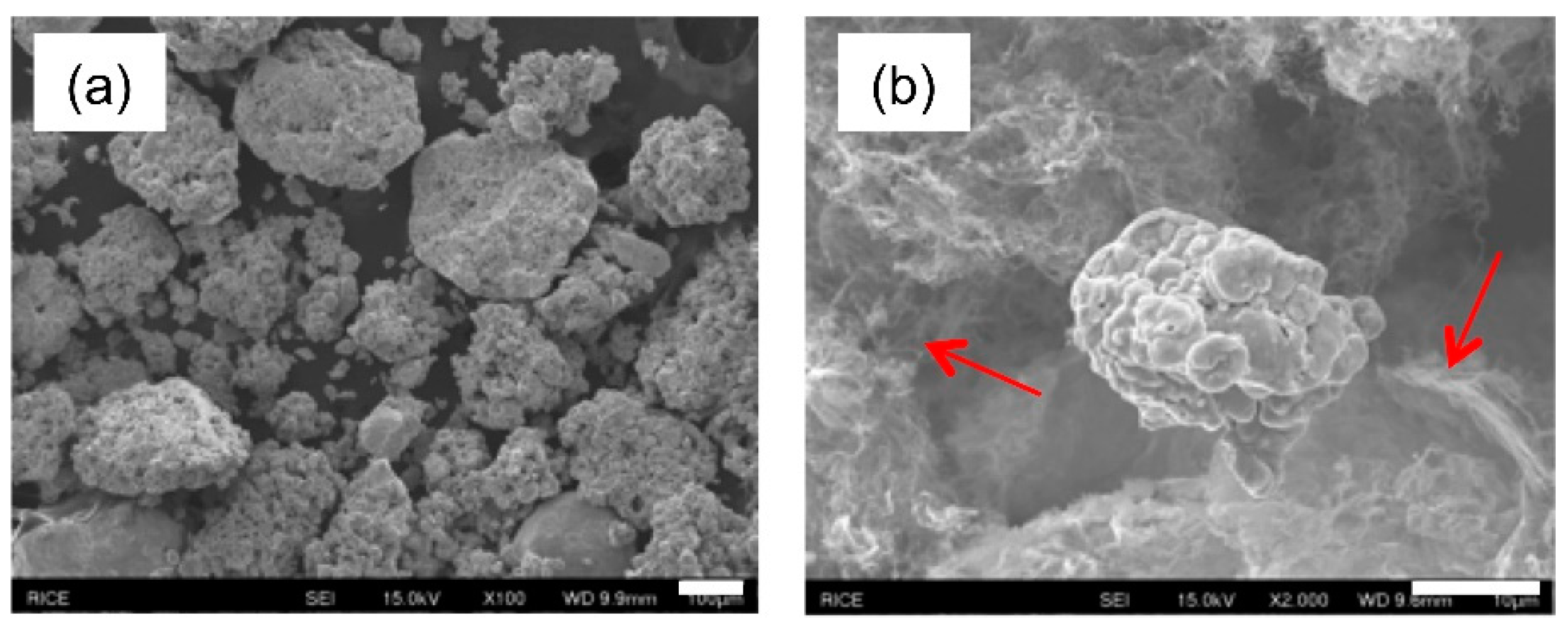
Figure 6 illustrates an SEM image of Cu micropowder (Sigma Aldrich, St Louis, MO, USA) and a physical mixture with SWCNTs. The Cu micropowder comprises aggregates (50–300 μm) of individual crystallites (263 (14) Å), while in the physically mixed sample, the SWCNTs are highly bundled and existed as physically separate domains surrounded by copper particles (Figure 6a,b).
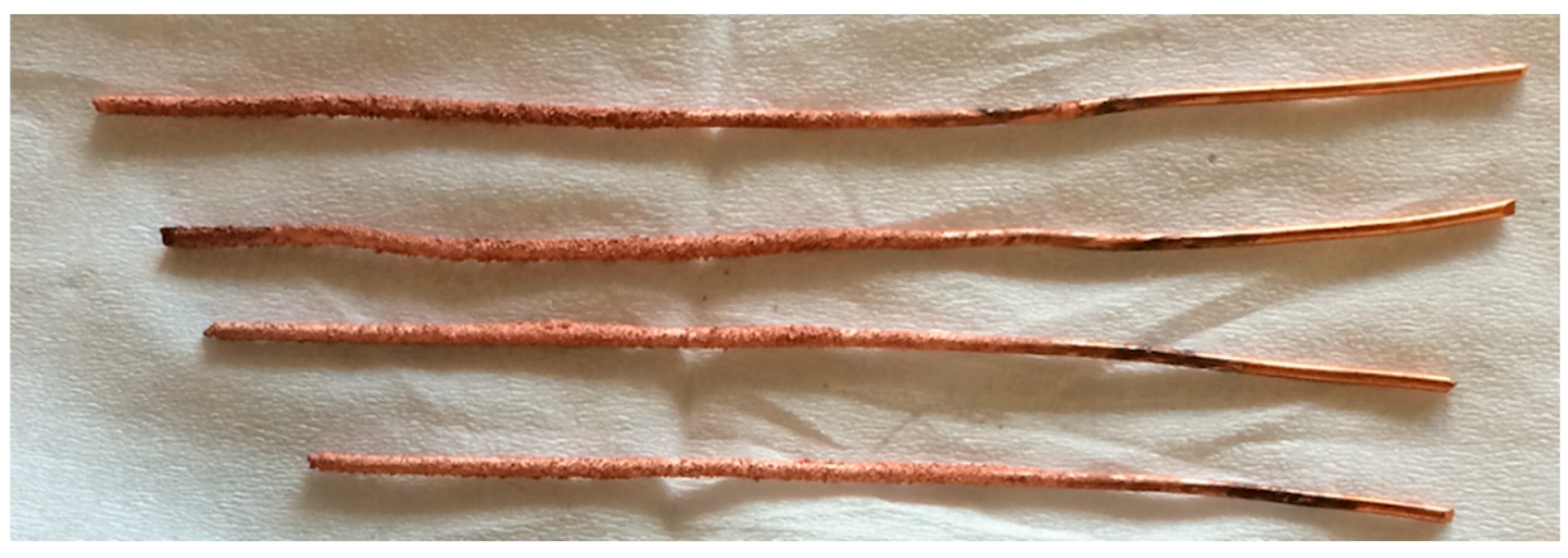
Electrolysis of SWCNTs/CuSO4 was performed in the presence of microscale copper powder dispersed in the stirring plating bath. A hard adherent coating thickness of 0.20 ± 0.05 mm was achieved over 2.75” coated lengths of the 16-gauge copper wire cathode (Figure 7). This is likely due to grain stabilization and dispersion hardening of copper grains by dispersed copper microparticles [48,49]. The adherent coatings held on to the electrode surface despite manual abrasion between fingers, or mild abrasion using tissue paper. Multiple cathodes were coated simultaneously (Figure S7), and on average, 0.11 ± 0.03 g of coating was deposited per wire cathode, translating to a total hard deposit of about 0.444 g over 27.5 cm of cathode surface (for the 4 copper wire cathodes combined). In addition, a porous deposit was also obtained, which appeared to contain the majority of the Cu micro powder.
SEM images of the hard coatings (Figure 8a) revealed large features formed from fused particles (10–50 μm), on which were smaller (1–2 μm) particles (Figure 8b). It is unclear from the SEM images if the SWCNTs are incorporated; however, the fine deposit obtained during the plating process was comprised more of fibrous bundles of SWCNTs (Figure 8c). The associated EDX data (Table 6) confirms the presence of C (and the Fe associated with the catalyst residue in the SWCNTs) in both samples. The carbon content (12.3 ± 7.4 at%) for the hard coating is higher than in samples prepared by electrolysis in the absence of added Cu micropowder. However, the porous deposit has significantly greater oxygen content than previously observed (c.f., Table 2; Table 6).

4. Conclusions

Copper–carbon nanotube composites possess several interesting mechanical and electrical properties and can be prepared through numerous techniques. Electroplating is one such technique and was used to generate both soft deposits containing controllable amounts of SWCNTs, and hard/adherent coatings of Cu–SWCNTs composites on copper wire cathodes. The morphology of the composites appeared to demonstrate a dependence on SWCNT content: the higher the SWCNT content, the less the dendritic nature of the electrodeposited copper. The presence of SWCNTs alters the nature of the native oxide on copper from CuO to Cu2O, while the presence of copper microparticles in the plating bath promoted the deposition of hard copper composite coatings on cathode surfaces. Importantly, despite their low dispersion, it is not necessary to employ a surfactant, a dispersing agent, or functionalization of the SWCNTs. This is a preliminary study aimed at generating composite sludge comprising mainly copper and added SWCNTs. Further follow-up studies are being planned in our research group with respect to optimizing the process, and subsequent steps to produce high ampacity electrical conductors.

Supplementary Materials

The following are available online at https://www.mdpi.com/2311-5629/5/3/38/s1: Figure S1: Image showing the association of the aggregates with the magnetic stir bar indicating the presence of the SWCNTs containing iron catalyst impurities; Figure S2: SEM images of HiPCO SWCNTs; Figure S3: SEM of copper wire cathode showing scratches likely produced during manufacture and subsequent handling; Figure S4. Photographic image of Cu–SWCNT composite deposited on the surface of the copper cathode after electrolysis using constant voltage (14 V) power supply: [Cu2+] = ~0.095 M, [SWCNT] = 2.3 wt%; Figure S5. Plot of copper (at%) versus carbon (at%) composition as determined by EDX analysis (R2 = 0.98). EDX shown as an average of 5 independent measurements per sample; Figure S6. Plot of iron (at%) versus carbon (at%) composition as determined by EDX analysis (R2 = 0.92). EDX shown as an average of 5 independent measurements per sample; Figure S7. Copper wire cathodes with hard coatings (Cu–SWCNT) before rinsing and drying.

Author Contributions

P.M.V.R. and A.R.B. conceptualized the study and developed the related methodology. Both authors co-wrote, reviewed, and edited the manuscript. C.E.G. and D.R.J. contributed in terms of XPS characterization and discussion of data. P.M.V.R. performed all electroplating experiments and all sample preparations for material characterization studies. SEM and EDX and related analyses were performed by G.L.E. and B.B. TGA and Raman analysis were performed by P.M.V.R. XRD analysis was conducted by J.L. A.R.B. contributed in terms of funding acquisition, project management, supervision, and overall guidance in the study.

Funding

Funding for this work was provided by the Office of Naval Research (N00014-15-2717), the Robert A Welch Foundation (C-0002), the Sêr Cymru National Research Network in Advanced Engineering and Materials (NRN-150) (A.R.B.), a Sêr Cymru II Welsh Fellowship (C.E.G.) part-funded by the European Regional Development Fund (ERDF), and Flexible Integrated Energy Systems (FLEXIS) operations funded by the Welsh European Funding Office (WEFO) through the Welsh Government.

Acknowledgments

The authors would like to acknowledge the assistance provided by Swansea University College of Engineering AIM Facility, which was funded in part by the EPSRC (EP/M028267/1), and the European Regional Development Fund through the Welsh Government (80708). Ewa Kazimierska of Swansea University is acknowledged for her insights into the theory of electroplating. Thanks are extended to John Marsh of Rice University for administration support and help with project management.

Conflicts of Interest

The authors declare no conflict of interest.

References

  1. Jarosz, P.; Schauerman, C.; Alvarenga, J.; Moses, B.; Mastrangelo, T.; Raffaelle, R.; Ridgley, R.; Landi, B. Carbon nanotube wires and cables: Near-term applications and future. Nanoscale 2011, 3, 4542–4553. [Google Scholar] [CrossRef] [PubMed]
  2. Hjortstam, O.; Isberg, P.; Soderholm, S.; Dai, H. Can we achieve ultra-low resistivity in carbon nanotube-based metal composites? Appl. Phys. A Mater. Sci. Process 2004, 78, 1175–1179. [Google Scholar] [CrossRef]
  3. Janas, D.; Liszka, B. Copper matrix nanocomposites based on carbon nanotubes or graphene. Mater. Chem. Front. 2018, 2, 22–35. [Google Scholar] [CrossRef]
  4. Jordan, M.B.; Feng, Y.; Burkett, S.L. Development of seed layer for electrodeposition of copper on carbon nanotube bundles. J. Vac. Sci. Technol. B Nanotechnol. Microelectron. 2015, 33, 02120201–02120208. [Google Scholar] [CrossRef]
  5. Subramaniam, C.; Sekiguchi, A.; Yamada, T.; Futaba, D.N.; Hata, K. Nano-scale, planar and multi-tiered current pathways from a carbon nanotube–copper composite with high conductivity, ampacity and stability. Nanoscale 2016, 8, 3888–3894. [Google Scholar] [CrossRef] [PubMed]
  6. Chai, G.; Sun, Y.; Sun, J.J.; Chen, Q. Mechanical properties of carbon nanotube–copper nanocomposites. J. Micromech. Microeng. 2008, 18, 0350131–0350134. [Google Scholar] [CrossRef]
  7. Arai, S.; Saito, T.; Endo, M. Cu–MWCNT composite films fabricated by electrodeposition. J. Electrochem. Soc. 2010, 157, D147–D153. [Google Scholar] [CrossRef]
  8. Daoush, W.M.; Lim, B.K.; Mo, C.B.; Nam, D.H.; Hong, S.H. Electrical and mechanical properties of carbon nanotube reinforced copper nanocomposites fabricated by electroless deposition process. Mater. Sci. Eng. A 2009, 513, 247–253. [Google Scholar] [CrossRef]
  9. Wright, K.D.; Gowenlock, C.E.; Bear, J.C.; Barron, A.R. Understanding the effect of functional groups on the seeded growth of copper on carbon nanotubes for optimizing electrical transmission. ACS Appl. Mater. Interfaces 2017, 9, 27202–27212. [Google Scholar] [CrossRef]
  10. Uddin, S.M.; Mahmud, T.; Wolf, C.; Glanz, C.; Kolaric, I.; Volkmer, C.; Höller, H.; Wienecke, U.; Roth, S.; Fecht, H.-J. Effect of size and shape of metal particles to improve hardness and electrical properties of carbon nanotube reinforced copper and copper alloy composites. Compos. Sci. Technol. 2010, 70, 2253–2257. [Google Scholar] [CrossRef] [Green Version]
  11. Varentsova, V.I.; Varenstov, V.K.; Bataev, I.A.; Yusin, S.I. Effect of surface state of carbon fiber electrode on copper electroplating from sulfate solutions. Prot. Met. Phys. Chem. 2017, 47, 43–47. [Google Scholar] [CrossRef]
  12. Arai, S.; Endo, M. Carbon nanofiber-copper composites fabricated by electroplating. Electrochem. Solid-State Lett. 2004, 7, C25–C26. [Google Scholar] [CrossRef]
  13. Arai, S.; Endo, M. Various carbon nanofiber–copper composite films prepared by electrodeposition. Electrochem. Commun. 2005, 7, 19–22. [Google Scholar] [CrossRef]
  14. Arai, S.; Endo, M. Carbon nanofiber–copper composite powder prepared by electrodeposition. Electrochem. Commun. 2003, 5, 797–799. [Google Scholar] [CrossRef]
  15. Yang, Y.L.; Wang, Y.D.; Ren, Y.; He, C.S.; Deng, J.N.; Nan, J.; Chen, J.G.; Zuo, L. Single-walled carbon nanotube-reinforced copper composite coatings prepared by electrodeposition under ultrasonic field. Mater. Lett. 2008, 62, 47–50. [Google Scholar] [CrossRef]
  16. Arai, S.; Saito, T.; Endo, M. Metal-fixed multiwalled carbon nanotube patterned emitters using photolithography and electrodeposition technique. Electrochem. Solid-State Lett. 2008, 11, D72–D74. [Google Scholar] [CrossRef]
  17. Arai, S.; Kirihata, K.; Shimizu, M.; Ueda, M.; Katada, A.; Uejima, M. Fabrication of Copper/Single-Walled Carbon Nanotube Composites by Electrodeposition Using Free-Standing Nanotube Film. J. Electrochem. Soc. 2017, 164, D922–D929. [Google Scholar] [CrossRef] [Green Version]
  18. Feng, Y.; McGuire, G.E.; Shenderova, O.A.; Ke, H.; Burkett, S.L. Fabrication of copper/carbon nanotube composite thin films by periodic pulse reverse electroplating using nanodiamond as a dispersing agent. Thin Solid Films 2016, 615, 116–121. [Google Scholar] [CrossRef]
  19. Raja, P.M.V.; Esquenazi, G.L.; Wright, K.D.; Gowenlock, C.E.; Brinson, B.E.; Alexander, S.; Jones, D.R.; Gangoli, V.S.; Barron, A.R. Aqueous electromigration of single-walled carbon nanotubes and co-electromigration with copper ions. Nanoscale 2018, 10, 19628–19637. [Google Scholar] [CrossRef] [Green Version]
  20. Kazimierska, E.; Andreoli, E.; Barron, A.R. Understanding the effect of carbon nanotube functionalization on copper electrodeposition. J. Appl. Electrochem. 2019, 49, 1–11. [Google Scholar] [CrossRef]
  21. Lee, S.M.; Raja, P.M.V.; Esquenazi, G.L.; Barron, A.R. Effect of raw and purified carbon nanotubes and iron oxide nanoparticles on the growth of wheatgrass prepared from the cotyledons of common wheat (triticum aestivum). Environ. Sci. Nano 2018, 5, 103–114. [Google Scholar] [CrossRef]
  22. Zhang, K.S.; Pham, D.; Lawal, O.; Ghosh, S.; Gangoli, V.S.; Smalley, P.; Kennedy, K.; Brinson, B.E.; Billups, W.E.; Hauge, R.H.; et al. Overcoming Catalyst Residue Inhibition of the Functionalization of Single-Walled Carbon Nanotubes via the Billups–Birch Reduction. ACS Appl. Mater. Interfaces 2017, 9, 37972–37980. [Google Scholar] [CrossRef] [PubMed]
  23. Moradi, O.; Zare, K.; Yari, M. Interaction of some heavy metal ions with single walled carbon nanotube. Int. J. Nano Dimens. 2011, 1, 203–220. [Google Scholar]
  24. Peng, C.; Liu, Y.; Bi, J.; Xu, H.; Ahmed, A.S. Recovery of copper and water from copper-electroplating wastewater by the combination process of electrolysis and electrodialysis. J. Haz. Mater. 2011, 189, 814–820. [Google Scholar] [CrossRef]
  25. Zhao, J.; Sun, L.; Canepa, S.; Sun, H.; Yesibolati, M.N.; Sherburne, M.; Xu, R.; Sritharan, T.; Loo, J.S.C.; Ager, J.W., III; et al. Phosphate tuned copper electrodeposition and promoted formic acid selectivity for carbon dioxide reduction. J. Mater. Chem. A 2017, 5, 11905–11916. [Google Scholar] [CrossRef] [Green Version]
  26. Zhou, H.; Liu, P.; Chen, X.; Li, W.; Liu, X. The influence of electro-deposition parameters on conductivity and morphology of structurally uniform MWCNTs/Cu composite films. Mater. Res. Express 2018, 5, 06560401–065660411. [Google Scholar] [CrossRef]
  27. Zhou, M.; Mai, Y.; Ling, H.; Chen, F.; Lian, W.; Jie, X. Electrodeposition of CNTs/copper composite coatings with enhanced tribological performance from a low concentration CNTs colloidal solution. Mat. Res. Bull. 2018, 97, 537–543. [Google Scholar] [CrossRef]
  28. Ogrin, D.; Chattopadhyay, J.; Sadana, A.K.; Billups, E.; Barron, A.R. Epoxidation and deoxygenation of single-walled carbon nanotubes: Quantification of epoxide defects. J. Am. Chem. Soc. 2006, 128, 11322–11323. [Google Scholar] [CrossRef]
  29. Nia, P.M.; Meng, W.P.; Lorestani, F.; Mahmoudian, M.R.; Alias, Y. Electrodeposition of copper oxide/polypyrrole/reduced graphene oxide as a nonenzymatic glucose biosensor. Sens. Actuators B Chem. 2015, 209, 100–108. [Google Scholar]
  30. Wang, L.C.; De Tacconi, N.R.; Chenthamarakshan, C.R.; Rajeshwar, K.; Tao, M. Electrodeposited copper oxide films: Effect of bath pH on grain orientation and orientation-dependent interfacial behavior. Thin Solid Film. 2007, 515, 3090–3095. [Google Scholar] [CrossRef]
  31. Chen, S.; Brown, L.; Levendorf, M.; Cai, W.; Ju, S.-Y.; Edgeworth, J.; Li, X.; Magnuson, C.W.; Velamakanni, A.; Piner, R.D.; et al. Oxidation resistance of graphene-coated Cu and Cu/Ni alloy. ACS Nano 2011, 5, 1321–1327. [Google Scholar] [CrossRef]
  32. Prasai, D.; Tuberquia, J.C.; Harl, R.R.; Jennings, G.K.; Bolotin, K.I. Graphene: Corrosion-inhibiting coating. ACS Nano 2012, 6, 1102–1108. [Google Scholar] [CrossRef] [PubMed]
  33. Chen, X.H.; Chen, C.S.; Xiao, H.N.; Cheng, F.Q.; Zhang, G.; Yi, G.J. Corrosion behavior of carbon nanotubes–Ni composite coating. Surf. Coat. Technol. 2005, 191, 351–356. [Google Scholar] [CrossRef]
  34. Rudd, J.A.; Gowenlock, C.E.; Gomez, V.; Kazimierska, E.; Al-Enizi, A.M.; Andreoli, E.; Barron, A.R. Solvent-free microwave-assisted synthesis of tenorite nanoparticle-decorated multi-walled carbon nanotubes. J. Mater. Sci. Technol. 2019, 35, 1121–1127. [Google Scholar] [CrossRef] [Green Version]
  35. Gomez, V.; Irusta, S.; Adams, W.W.; Hauge, R.H.; Dunnill, C.W.; Barron, A.R. Enhanced carbon nanotubes purification by physic-chemical treatment with microwave and Cl2. RSC Adv. 2016, 6, 11895–11902. [Google Scholar] [CrossRef]
  36. Biesinger, M.C. Advanced analysis of copper X-ray photoelectron spectra. Surf. Interface Anal. 2017, 49, 1325–1334. [Google Scholar] [CrossRef]
  37. Galtayries, A.; Bonnelle, J.-P. XPS and ISS studies on the interaction of H2S with polycrystalline Cu, Cu2O and CuO surfaces. Surf. Interface Anal. 1995, 23, 171–179. [Google Scholar] [CrossRef]
  38. Skinner, W.M.; Prestidge, C.A.; Smart, R.S.C. Irradiation effects during XPS studies of Cu (II) activation of zinc sulphide. Surf. Interface Anal. 1996, 24, 620–626. [Google Scholar] [CrossRef]
  39. Zheng, M.; Diner, B.A. Solution redox chemistry of carbon nanotubes. J. Am. Chem. Soc. 2004, 126, 15490–15494. [Google Scholar] [CrossRef]
  40. Hsieh, H.-S. Carbon Nanotube Mediated Redox Reactions in Water. Ph.D. Thesis, Purdue University West Lafayette, West Lafayette, IN, USA, 2015. [Google Scholar]
  41. Liu, Y.; Hu, J.; Hu, A.; Li, M.; Mao, D. Oxidation of the copper alloy with pure copper plating. J. Adhes. Sci. Technol. 2012, 26, 2653–2660. [Google Scholar] [CrossRef]
  42. Liu, C.-W.; Wang, Y.-L.; Tsai, M.-S.; Feng, H.-P.; Chang, S.-C.; Hwang, G.-J. Effect of plating current density and annealing on impurities in electroplated Cu film. J. Vac. Sci. Technol. A 2005, 23, 658–662. [Google Scholar] [CrossRef]
  43. Wu, C.-W.; Harroun, S.G.; Lien, C.-W.; Chang, H.-T.; Unnikrishnan, B.; Lai, I.P.-J.; Chang, J.-Y.; Huang, C.-C. Self-templated formation of aptamer-functionalized copper oxide nanorods with intrinsic peroxidase catalytic activity for protein and tumor cell detection. Sens. Actuators B Chem. 2016, 227, 100–107. [Google Scholar] [CrossRef]
  44. Kim, K.; Johnson, R.W.; Tanskanen, J.T.; Liu, N.; Kim, M.G.; Pang, C.; Ahn, C.; Bent, S.F.; Bao, Z. Selective metal deposition at graphene line defects by atomic layer deposition. Nat. Comm. 2014, 5, 4781. [Google Scholar] [CrossRef] [PubMed] [Green Version]
  45. Hussain, S.; Pal, A.K. Incorporation of nanocrystalline silver on carbon nanotubes by electrodeposition technique. AIP Conf. Proc. 2008, 1063, 98–104. [Google Scholar]
  46. Dresselhaus, M.S.; Pimenta, M.A.; Ecklund, P.C.; Dresselhaus, G. Raman Scattering in Materials Science; Springer: Berlin, Germany, 2000. [Google Scholar]
  47. Schönfelder, R.; Avilés, F.; Knupfer, M.; Azamar-Barrios, J.A.; González-Chi, P.I.; Rümmeli, M.H. Influence of architecture on the Raman spectra of acid-treated carbon nanostructures. J. Exp. Nanosci. 2014, 9, 931–941. [Google Scholar] [CrossRef]
  48. Ferkel, H.; Müller, B.; Riehemann, W. Electrodeposition of particle-strengthened nickel films. Mater. Sci. Environ. A 1997, 234, 474–476. [Google Scholar] [CrossRef]
  49. Low, C.T.J.; Walsh, F.C. Multifunctional Materials for Tribological Applications; Wood, R.J.K., Ed.; Pan Stanford: Singapore, 2015. [Google Scholar]
Figure 1. Representative SEM images of electroplated copper single walled carbon nanotube (Cu–SWCNT) composites electrodeposited (at a bath temperature of 60 °C) using 0 wt% SWCNT (a,b), 2.3 wt% SWCNT (c,d), 3.8 wt% SWCNT (e,f), and 6.2 wt% SWCNT (g,h). Scale bar = 100 μm (a,c,e,g) and 1 μm (b,d,f,h).
Carbon 05 00038 g001
Figure 2. Plot of carbon (wt%) determined by EDX analysis versus carbon (wt%) added in the form of SWCNTs to the electrolysis (R2 = 0.95). EDX shown as an average of 5 independent measurements per sample.
Carbon 05 00038 g002
Figure 3. High resolution Cu 2p XPS showing the presence of copper oxidation states in (a) electrodeposited copper and (b) Cu–SWCNT composite deposited with 3.8 wt% SWCNTs in CuSO4 (0.1 M) solution at a bath temperature of 60 °C.
Carbon 05 00038 g003
Figure 4. XRD of (a) electrodeposited copper and (b) Cu–SWCNT composite deposited with 4.0 wt% SWCNTs in CuSO4 solution at a bath temperature of 60 °C, showing the presence of Cu (ICDD #04-009-2090), CuO (ICDD #04-007-1375), and Cu2O (ICDD #04-002-3214).
Carbon 05 00038 g004
Figure 5. Raman spectra (514 nm) of (a) HiPCO SWCNTs before electrolysis, (b) Cu–SWCNT composite deposited with 6.2 wt% SWCNTs in CuSO4 solution at a bath temperature of 60 °C, (c) Cu deposited from CuSO4 solution at a bath temperature of 60 °C showing the peak for CuO, and (d) the hard adherent Cu–SWCNT coatings formed from electrolysis in the presence of Cu micropowder.
Carbon 05 00038 g005
Figure 6. SEM images of (a) copper micropowder and (b) a physical mixture of copper micropowder with HiPCO SWCNTs. SWCNTs are seen in (b) as highly bundled species segregated into domains (indicated by the arrows) among the copper particles suggesting poor mixing. Scale bar = 100 μm (a) and 10 μm (b).
Carbon 05 00038 g006
Figure 7. Examples of dried copper wire cathodes with a hard adherent Cu–SWCNT composite coating.
Carbon 05 00038 g007
Figure 8. SEM images of hard adherent coatings (a,b) and related porous deposit (c) as obtained through the modified electrochemical plating process on copper wire cathodes.
Carbon 05 00038 g008
Table 1. Composition of electrolysis bath, electrodeposition time, and yield of products.
Reaction Volume (mL)SWCNT (mg)Electrodeposition Time (min)Air-Dried Product (mg)SWCNT (wt%)
750903500.0
150172107532.3
10017904503.8
6017902746.2
Table 2. EDX analysis of electroplated Cu–SWCNT composites electrodeposited at a bath temperature of 60 °C.
SWCNT (wt%)C (at%)O (at%)Cu (at%)Fe (at%)
0.01.1 ± 0.48.4 ± 0.690.0 ± 1.70.7 ± 0.7
2.318.3 ± 2.31.3 ± 0.377.6 ± 4.01.5 ± 0.5
3.820.0 ± 2.42.0 ± 0.276.5 ± 2.51.3 ± 0.5
6.230.6 ± 7.01.5 ± 0.365.7 ± 7.22.2 ± 0.1
Table 3. Chemical composition of copper estimated from the relative areas of components within the Cu 2p XPS spectra of Cu–SWCNT composites electrodeposited at a bath temperature of 60 °C. 1.
SWCNT (wt%)Cu and Cu2O (at%)CuO (at%)Cu(OH)2 (at%)
0.043.912.943.2
3.862.737.3
1 Contributions from Cu and Cu2O are not easily distinguished from each other due to the close proximity of the associated components.
Table 4. Chemical composition and crystal grain size as determined by XRD of Cu–SWCNT composites electrodeposited at a bath temperature of 60 °C. 1.
CompositionCrystal Grain Size
SWCNT (wt%)Cu (wt%)Cu2O (wt%)CuO (wt%)Cu (Å)Cu2O (Å)CuO (Å)
0.070.0 (4)30.0(4)244 (15)64 (11)
2.398.7 (2)1.3 (2)201 (3)117
3.897.5 (2)2.5 (2)254 (17)306
6.299.2 (2)0.8 (2)202 (10)145
1 Error values given in parentheses. Weak signals pertaining to Cu2O enabled to the analytics software to yield only singular data without error determination.
Table 5. The IG:ID ratio determined from the Raman spectrum (514 nm) of Cu–SWCNT composites electrodeposited at a bath temperature of 60 °C.
SWCNT (wt%)IG:ID 1
0.0N/A
2.311.43 (0.75)
3.812.43 (1.46)
6.210.18 (1.93)
1 All samples averaged from 3 regions of the sample and standard deviations are given in parenthesis.
Table 6. EDX analysis of electroplated Cu–SWCNT composites electrodeposited at a bath temperature of 60 °C in the presence of micropowder copper.
SWCNT (wt%)C (at%)O (at%)Cu (at%)Fe (at%)
Hard coating12.3 ± 7.47.7 ± 4.076 ± 123.7 ± 0.5
Porous deposit10.1 ± 2.520.6 ± 7.965.7 ± 4.43.4 ± 1.0