1. Introduction
The rapid expansion of the global market for consumer electronic and electric vehicles requires high performance energy storage units, especially with high energy density and high power density, while still retaining good cyclability [
1,
2,
3]. Lithium-ion battery (LIB) and electrochemical capacitor (EC) are the most widely used energy storage technology in these electronic products, but they occupy opposite ends of performance spectrum [
4,
5]. Typically, LIBs exhibit high energy density due to their faradaic energy storage processes, but they deliver low power density, slow charge and discharge rate, and limited cyclability. On the other hand, ECs are based on non-faradaic electrochemical double layer capacitance (EDLC) storage mechanism or pseudocapacitive faradaic reactions, thus enabling higher power density, fast charge, and discharge rate, as well as longer cyclability than LIBs, although they exhibit relatively lower energy density. Lithium ion capacitor (LIC) represents a stand-alone energy storage system that is capable of combining the positive attributes of LIB and EC to provide relatively high energy density, high power density, and good cyclability [
6,
7]. LICs are typically constructed using an LIB electrode as battery-type anode and an EC electrode as capacitor-type cathode. Capacitor-type electrode that is capable of fast charge-discharge kinetics and high surface area, high specific capacity is a key requirement for the high energy performance of LICs [
3,
8,
9]. Moreover, the energy density of the system is usually constrained by the specific capacity of battery-type graphite electrodes. It is expected that LIC energy density can be improved by utilizing electrodes that are capable of offering higher specific capacity in place of traditional activated carbon and graphite.
Owing to the advantageous properties of graphene in terms of specific capacity, specific surface area (SSA), chemical stability, and electrical conductivity, many studies have demonstrated high performance LIC using graphene-based electrodes [
3,
8,
10,
11,
12,
13,
14,
15,
16,
17]. In recent years, more efforts are being made to fine-tune the material to further enhance its properties to advance the electrochemical performance of LICs. Some of the efforts include carrying out activation procedures to achieve improved SSA [
8], doping [
16], compositing with other materials [
14], and functionalization [
17], using various approaches. However, most of the graphene-based electrode fabrication approaches present challenges, such as cumbersome processes, high-temperature heating in inert atmospheres, and utilization of toxic chemicals, which raises convenience and environmental concerns.
Photoreduction of graphene oxide (GO) has been demonstrated in literature as a simple and environmentally benign approach of preparing graphene-based capacitor electrode [
18,
19,
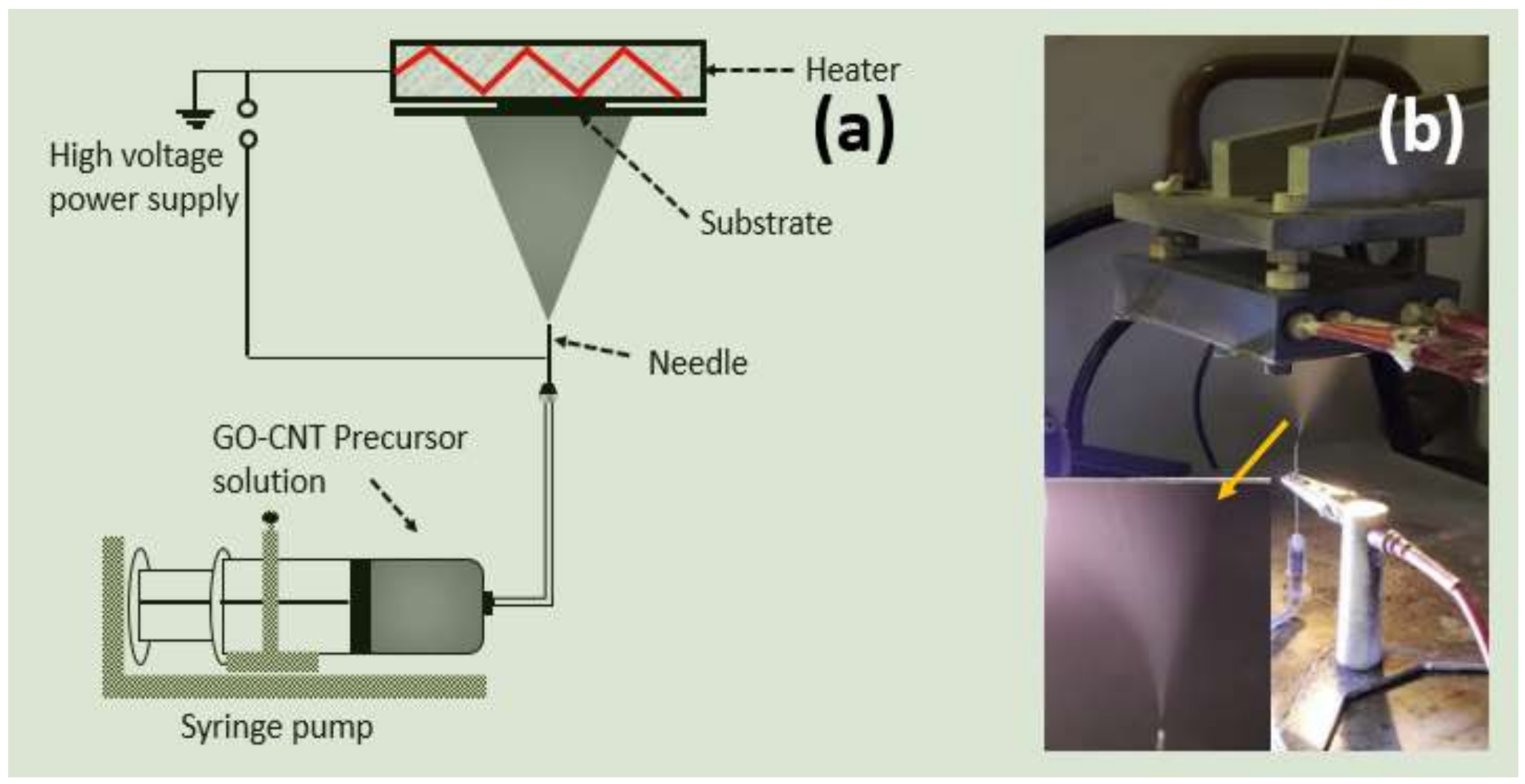
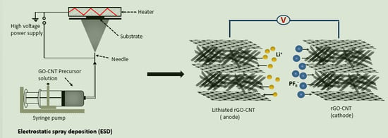
20]. Electrostatic spray deposition (ESD) is another interesting approach in which the graphene-based electrode may be obtained by simply spraying GO precursor solution electrostatically on a heated current collector. Schematic illustration and a practical image of the ESD process are presented in
Figure 1. ESD offers a rapid and simple electrode fabrication approach [
21,
22]. GO precursor solution and ESD process parameters can be easily controlled in order to obtain numerous morphologies that may influence the electrochemical properties of the graphene-based electrode. It also enables the direct binder-free deposition and reduction of GO on a current collector simultaneously.
Previous work from our group demonstrated promising electrochemical performance of ESD-based reduced graphene oxide-carbon nanotube (rGO-CNT) electrode for micro-supercapacitors [
21]. The rGO-CNT exhibits high specific capacity, rate capability, and superior time constant, thus making it an attractive candidate for LIC, especially as a capacitor-type cathode. Meanwhile, rGO-CNT is considered to be a promising battery-type anode [
23]. In this work, we exploit the capability of ESD-based rGO-CNT by employing the material as both an anode and cathode for LIC. The anode was electrochemically pre-lithiated prior to the LIC cell assembly, while as-prepared rGO-CNT was used as cathode. The LIC operated within a voltage range of 0.01–4.3 V, and it delivered a maximum energy density of 114.5 Wh kg
−1 and maximum power density of 2569 W kg
−1.
2. Materials and Methods
A similar method that was previously reported in [
21] was used for the electrode preparation. Briefly, the starting materials, GO powder (0.7–1.2 nm thickness and 300–800 nm dimension) and COOH-functionalized multiwalled CNT (8–15 nm diameter, 10–50 μm length and <1.5 wt. % functional group content) were obtained from Cheaptubes Inc., Cambridgeport, VT, USA. The GO powder (18 mg) was mixed with CNT (2 mg) and was dispersed in 1,2-propanediol (20 mL) by an ultrasonic probe (750 W, 20 KHz, Sonics and materials Inc., Newtown, CT, USA) to obtain a 1 mg mL
−1 GO-CNT precursor suspension. The precursor was then drawn into a syringe with a stainless steel needle and it was connected to a syringe pump that was kept at a rate of 4 mL h
−1. The distance between the tip of the needle and the stainless steel substrates was kept at 4 cm. The substrates were mounted on the ESD set-up and preheated to 250 °C before the deposition process. The precursor solution was sprayed on the heated stainless steel substrates for 2 h by applying a voltage of 5–6 kV through the stainless steel needle of the syringe. The mass loading that was obtained ranged from 0.2 to 0.8 mg cm
−2 (thickness ca. 2.5 to 5.2 μm). For comparison, pure rGO and CNT electrodes were also prepared using similar steps.
The surface functionalities of the samples were revealed by Fourier transform infrared (FTIR) (JASCO FT/IR, 4100, Tokyo, Japan), while the morphology of the samples were examined with scanning electron microscope (SEM) (FE-SEM, JEOL, Peabody, MA, USA). The structural properties of the samples were also studies with X-ray diffractometer (XRD) (Siemens, Munich, Germany) with Cu Kα radiation (λ = 1.5418 Å), which were operated at a current and voltage of 35 mA and 40 kV, respectively.
The samples were assembled in CR2032 coin cells with lithium as both counter and reference electrode for the half-cell experiments. The cells were assembled in an argon filled glove box using 1 M LiPF
6 in EC: EMC (Sigma Aldrich, St. Louis, MO, USA) as electrolyte and polypropylene membranes as separators. The potential windows were 0.01–3.0 V and 2.0–4.0 V for the anode and the cathode, respectively. For full cell assembly, electrochemical pre-lithiation process was first carried out on rGO-CNT anode by cycling six times in a half-cell assembly at a current density of 0.1 Ag
−1. Thereafter, the pre-lithiated anode was disassembled and was coupled with fresh rGO-CNT cathode with electrolyte and separator in CR2032 coin cell. The electrochemical performance of the LIC was evaluated within a voltage window of 0.01–4.3 V (mass ratio of cathode and anode was 4:1). Electrochemical evaluations were performed on the cells by using a NEWARE battery test system (BTS-610, Shenzhen, China) and a VMP3 multichannel potentiostat (VMP3, Bio Logic, Knoxville, TN, USA). The energy density E (Wh kg
−1) and power density P (W kg
−1) of the LIC device were calculated using the following equations [
9]:
where
t1 and
t2 (h) are the initial and final time of discharge with the voltage range
(V) and
(A kg
−1) is constant current density.
3. Results and Discussion
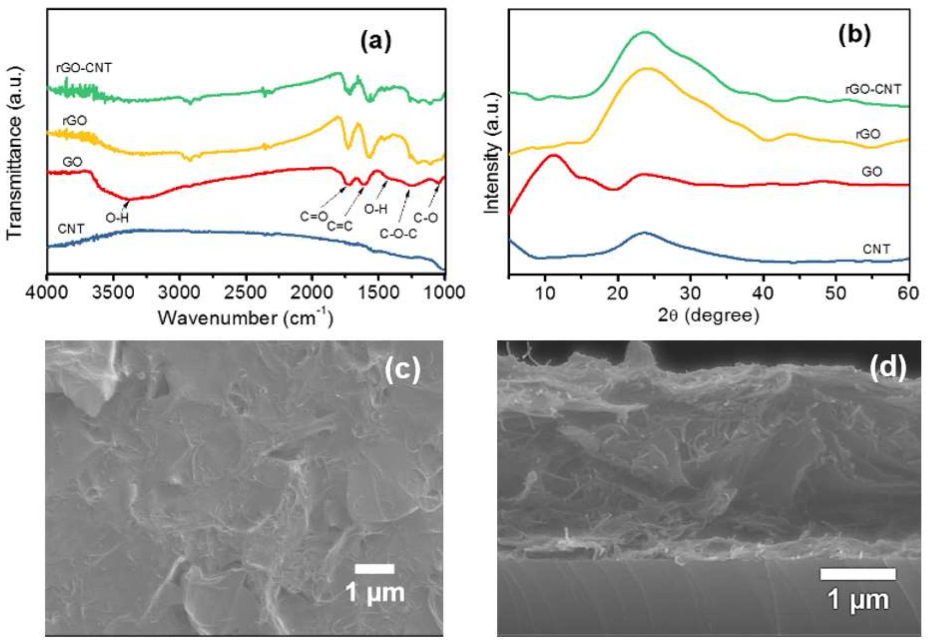
The surface properties of rGO-CNT film in comparison with GO, rGO, and CNT were studied with FTIR. The FTIR patterns of the samples are presented in
Figure 2a. The broad transmission peak centered around 3352 cm
−1 in the pattern corresponding to GO is related to O–H stretching, while the peak at ca. 1726 cm
−1 indicates the stretching of the C=O functional group in the GO structure [
24]. Furthermore, the peak at ca. 1635 cm
−1 indicates C=C stretching [
25], while the peak at ca. 1361 cm
−1, is related O–H bending. Other peaks at ca. 1226 and 1083 cm
−1 correspond to C–O–C and C–O groups, respectively [
26]. The peaks at 3352, 1361, 1226, and 1083 cm
−1 in the rGO and the rGO-CNT patterns appear to be mitigated, which indicates that GO was thermally reduced after the deposition. No significant peak was observed in the FTIR pattern of CNT. This may be attributed to the marginal functional group content (<1.5 wt. %) in the CNT when compared to that of GO, rGO, and rGO-CNT within the scale of comparison. However, peaks at 1729, 1618, and 1083 cm
−1 remain in the resulting rGO and rGO-CNT film, indicating the presence of corresponding oxygen functional groups after the deposition. A comparison of surface properties of the rGO-CNT composite and its components can be further analyzed by X-ray photoelectron spectroscopy (XPS), which would be incorporated in our future work. The surface The contribution of residual oxygen functional groups in enhancing the electrochemical performance of graphene-based materials, especially when being used as a capacitive storage material has been shown in previous studies in the literature [
27,
28].
The XRD patterns of GO, CNT rGO, and rGO-CNT film are presented in
Figure 2b. The XRD pattern of the starting GO shows a clear diffraction peak at 11.08°, corresponding to an interlayer spacing of 7.98 Å based on Bragg’s equation. The rGO and rGO-CNT XRD patterns show broad diffraction peaks at 24.38° and 23.75°, corresponding to interlayer spacing of 3.65 Å and 3.74 Å, respectively. A broad peak centered around is 23.68° was observed for CNT. The disappearance of 11.08° peak in rGO and rGO-CNT samples signifies the reduction of GO after the ESD process, which is in agreement with the FTIR results. Moreover, the slight shift in the peak position of rGO-CNT to lower 2θ angle with an increase in interlayer spacing when compared with rGO may be attributed to the insertion of CNT in-between rGO layers, which is also in good agreement with previous studies [
23]. SEM images of the surface and cross-section of the rGO-CNT film are shown in
Figure 2c,d, respectively. The surface SEM image shows wrinkled rGO sheets. The cross-sectional image indicates that the CNTs are entangled within the bulk of the rGO film. As noted in previous studies, the interconnection of CNT with rGO sheets can prevent or minimize restacking of the two-dimensional (2D) material during electrochemical cycling and boost its electron/ionic conductivity [
21,
23]. Moreover, the cross-sectional SEM image shows that the rGO-CNT film exhibits loose and open channels, which is expected to enable enhanced electrolyte ion accessibility, which is favorable for improved electrochemical performance.
The cyclic voltammograms (CVs) of the rGO-CNT anode half-cell is presented in
Figure 3a, within a voltage window of 0.01–3.0 V. An irreversible reduction peaks can be observed at ca. 0.5 V in the first cycle, which may be associated with solid electrolyte interface (SEI) reaction. Thereafter, prominent anodic peaks close to 0.2 V can be observed in the CV curves from the second to the 10th cycle, indicating the reversible lithiation/delithiation reaction (
) after the first cycle due to the isolation of the anode material and the electrolyte by SEI film [
29].
Figure 3b shows the galvanostatic charge-discharge (GCD) curves of the material at 0.1 Ag
−1 current density with an initial discharge capacity of 1917 mAhg
−1, which also suggests SEI formation on the surface of the rGO-CNT [
29,
30]. Two flat plateaus can be observed on the initial discharge curve, starting at ca. 0.5 V and ca.0.2 V. Similar to CV test results, the 0.5 V plateau may be related to SEI reaction while the 0.2 V plateau suggests lithiation potential of the material. The discharge capacity decreased to 1091 mA hg
−1 in the second cycle, indicating 44.6% initial capacity loss. We can see that, starting from the second cycle; the discharge capacity gradually decreases but became more reversible. Moreover, disappearance of the ca. 0.5 V plateau related to SEI reaction can be observed. The rate capability test result of the rGO-CNT shown in
Figure 3c shows that a discharge capacity of 990 mAhg
−1 was measured at 0.1 Ag
−1 current density after the first 30 cycles, which is significantly higher than that of rGO and CNT. The capacity rapidly decreases with increasing current density. A similar trend can be seen for both rGO and CNT, but the discharge capacity of rGO-CNT is superior in the current densities from 0.1 to 2 Ag
−1. The result shows that the rGO-CNT can still deliver a discharge capacity of 598 mAg
−1 at high current density of 2 Ag
−1. The material also showed good reversibility and cyclability after returning the current density to 0.1 Ag
−1, delivering slightly higher discharge capacity of ca.1025 mAhg
−1 after 70 subsequent cycles. Electrochemical impedance spectroscopy (EIS) was carried out to gain insight into the electrochemical characteristics of the rGO-CNT electrode material. As shown in
Figure 3d, both rGO-CNT and rGO exhibits suppressed semicircle in the high-frequency region, which corresponds to their charge transfer resistance at electrode/electrolyte interface [
31,
32]. An inclined line in the low frequency region can also be observed in the EIS data that is related to lithium-ion diffusion through the electrode. In comparison with rGO, rGO-CNT shows a smaller charge transfer impedance and improved lithium ion diffusion behavior, which supports the charge- discharge characteristic that was observed.
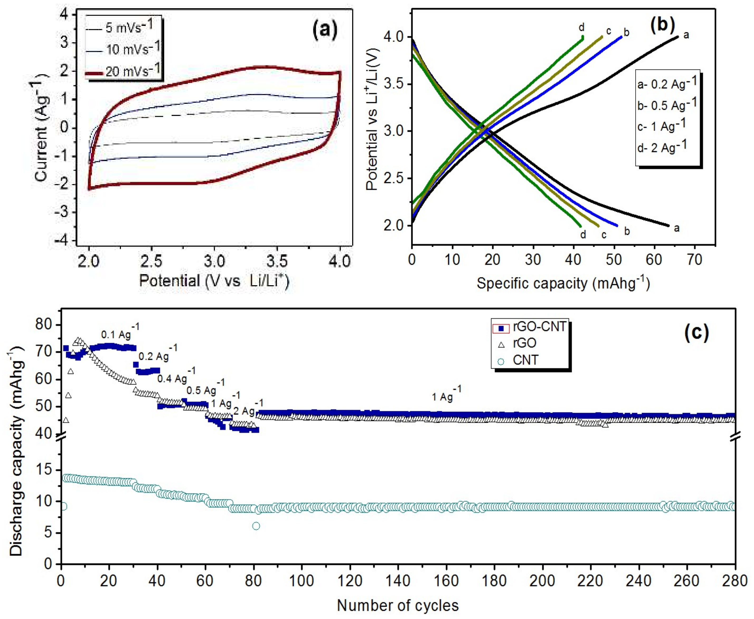
The rGO-CNT cathode material was tested in lithium half-cell configuration within a voltage window of 2.0–4.0 V. The CV curves of the rGO-CNT cathode at scan rates of 5, 10, and 20 mVs
−1 are presented in
Figure 4a. Rectangular shapes of typical capacitive storage mechanism can be observed on the curves, but with slight humps. The appearance of these humps suggest faradaic pseudocapacitive storage mechanism contribution besides non-faradaic EDLC mechanism due to the presence of residual oxygen functional groups in the material, which is similar to previous studies in the literature [
27,
28]. This observation suggests lithium-ion pseudocapacitive interaction with residual functional groups on the rGO-CNT. Charge-discharge curves of the rGO-CNT cathode material at different current densities are presented in
Figure 4b. A slight distortion from typical linear shape can be seen, especially at 0.2 Ag
−1, indicating that both EDLC and pseudocapacitive storage mechanisms coexist. The GCD became more linear with increasing the current density. An explanation for this observation is that at low current density, both EDLC and pseudocapacitive storage mechanism, contribute to the capacity of the material. As the current density increases the EDLC storage mechanism dominates. Moreover, an iR drop can be observed on the GCD curves related to the overall resistance of the cell [
21]. As shown in
Figure 4c, after 30 cycles, the rGO-CNT cathode half-cell delivered a discharge capacity of 72 mAhg
−1 at 0.1 Ag
−1 after 30 cycles, which exceeds the discharge capacity of 58 and 13 mAhg
−1 observed for rGO and CNT respectively. Moreover, rGO cathode half-cell showed an increasing discharge capacity until the eighth cycle, when it started decreasing. This behavior can be attributed to the effect of electrochemical activation of the rGO [
21].Lithium ions insert between graphene layers and gradually increase the accessibility of ions to the surface of graphene resulting in the increasing capacity in the first eight cycles during cycling. However, the decreasing capacity after the eighth cycle suggests the decreasing accessibility of ions due to the possible restacking of the graphene layers during electrochemical cycling. In contrast, the rGO-CNT showed relatively stable performance during cycling, indicating the effectiveness of CNT, which acts as a nanospacer to prevent/minimize the restacking issue, which is in line with previous report from our group [
21]. Rate capability and cyclability test (
Figure 4c) of the half-cell shows that the rGO-CNT delivered a discharge capacity of 63.4, 60, 50.7, 46, and 41.7 mAhg
−1 at current densities of 0.2, 0.4, 0.5, 1, and 2 Ag
−1, respectively. The discharge capacities that were measured for the rGO-CNT are of similar values with that of rGO at the current densities of 0.4 to 2 Ag
−1, but higher than that of the discharge capacities of CNT. A discharge capacity of 46.7 mAhg
−1 was observed for the rGO-CNT after 200 subsequent cycles at a current density of 1 Ag
−1, which significantly exceeds the CNT discharge capacity, but it only slightly exceeds that of rGO (44.9 mAhg
−1).
To exploit the advantages of the rGO-CNT electrodes, an LIC was assembled by coupling the electrochemically pre-lithiated rGO-CNT as anode and as-prepared rGO-CNT as cathode. The schematic illustration of the LIC is presented in
Figure 5a. The cathode and the anode mass ratio was kept at 4:1 (total mass −1.72 mg).
Figure 5b shows the CV curves of the rGO-CNT//lithiated rGO-CNT at 20, 50, and 100 mVs
−1. The LIC could reach up to a maximum voltage limit of 4.3 V. The quasi-rectangular shape of the CV curves indicates the capacitive behavior of the electrochemical system. The deviation from the rectangular shape that was observed in the curve can be attributed to the overlapping faradic and the non-faradaic energy storage mechanism in the LIC. The GCD curves of the LIC within the same voltage window of 0.01–4.3 V at 0.1 to 1 Ag
−1 is presented in
Figure 5c. We can see that the GCD curves in
Figure 5c exhibits a slightly distorted triangular shape, also indicating capacitive behavior. The rate capability test (
Figure 5d) shows that the LIC delivered a discharge capacity of 66.9, 48.8, 40.4, 22.5, and 15.5 mAhg
−1 at current densities of 0.1, 0.2, 0.5, 1, and 2 Ag
−1, respectively, which were normalized by the weight of both the anode and the cathode. Moreover, as shown in
Figure 5e, the LIC delivered a discharge capacity of 9.2 mAhg
−1 at a current density of 2 Ag
−1 after 2000 cycles, indicating a 68.5% capacity retention. Our full cell performance indicates that both cathode and anode need to be charge balanced to maximize the performance of the LIC. It also requires the matching of ion transport kinetics between the two electrodes which exhibit dissimilar storage mechanisms (intercalation/deintercalation mechanism at anode side and EDLC mechanism at the cathode). In our system, the mass ratio between the cathode and the anode is 4:1, which is far from the idea mass matching according to the half-cell performance. Therefore, the results show that rGO-CNT LIC system is cathode limiting, indicating that the capacity of the full cell is mainly determined by the performance of the cathode side. In fact, the specific capacity of the LIC just based on cathode loading is comparable to that of the cathode half-cell at low current density (<1 Ag
−1), while at higher current densities (>1 Ag
−1), the anode becomes the limiting electrode because the reaction kinetics of anode is sluggish at a higher rate. Furthermore, if the capacities of the ESD based rGO-CNT electrodes were fully matched in the LIC system, then a remarkably higher energy and power density could be expected.
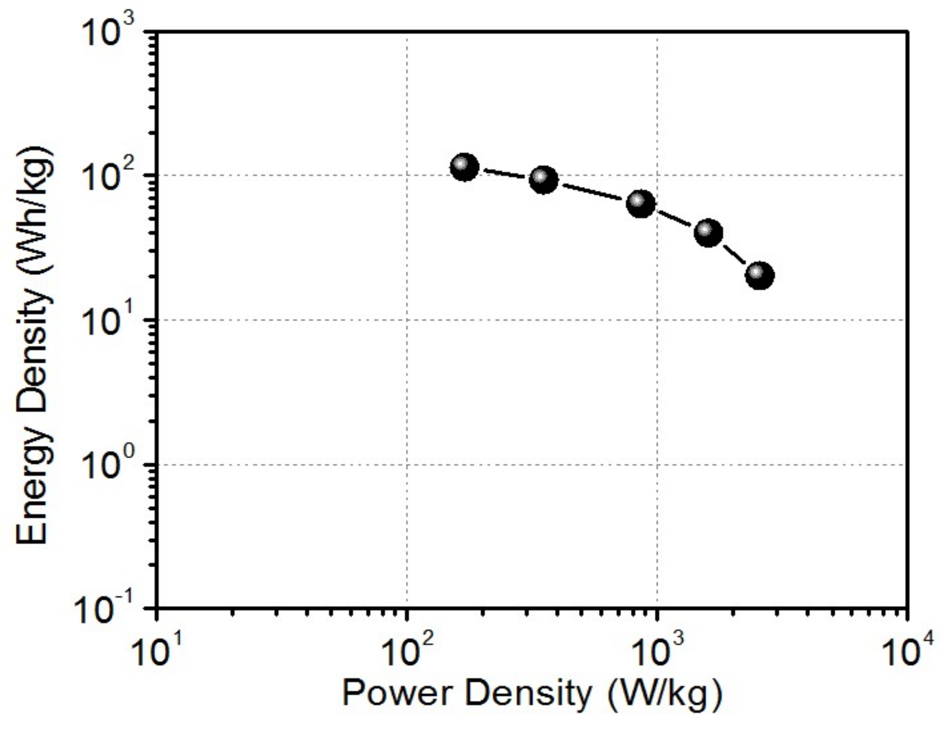
The Ragone chart of the LIC is presented in
Figure 6, showing energy density as high as 114.5 Wh kg
−1 and a maximum power density of 2569 W kg
−1, as calculated from the 10th cycle of discharge curves. The performance comparison of rGO-CNT//lithiated rGO CNT LIC with other LICs reported in literature is presented in
Table 1. The energy and power density characteristics of the LIC are superior to Graphene//AC LIC system [
31]. The LIC performance is comparable to graphite//functionalized graphene [
17], graphitic carbon//AC [
33], LIC in terms of energy density, and Fe
3O
4/graphene//Porous three-dimensional (3D) graphene LIC system considering power density [
11]. Its performance is however lower than flash-reduced graphene oxide//porous 3D graphene LIC, which is a fully optimized system [
12]. The electrochemical performance of our LIC system is conceivably limited by capacity and ion transport kinetics mismatch between the two electrodes that exhibit dissimilar storage mechanisms (intercalation/deintercalation mechanism at anode side and EDLC mechanism at the cathode). If the capacities and ion transport kinetics in the ESD based rGO-CNT electrodes are fully matched in the LIC system, then a significantly improved electrochemical performance could be expected.
This work indicates a promising approach for the facile fabrication of graphene-based electrodes for high performance LICs. The open channels of the rGO-CNT composite that was derived from the ESD facilitates better electron/ion transport when compared to the single component rGO or CNT. Even though the anode exhibits large capacity, it is most likely relatively sluggish as compared to the cathode side in the full cell, thereby limiting the overall electrochemical performance of the full cell. The LIC performance could be further improved by increasing the cathode capacity, improving the reaction kinetics, and balancing the total charge contributing to the reversible reaction.
