Communication

An Innovative Solution Method for the Evaluation of CO2 Disposal in the Seafloor Environment

by
Boyun Guo
*,
Muhammad Towhidul Islam
and
Vincent Nana Boah Amponsah
Energy Institute of Louisiana, University of Louisiana at Lafayette, Lafayette, LA 70508, USA
*
Author to whom correspondence should be addressed.
Submission received: 11 July 2025 / Revised: 9 October 2025 / Accepted: 24 October 2025 / Published: 27 October 2025
(This article belongs to the Section Carbon Cycle, Capture and Storage)

Abstract

Injecting carbon dioxide (CO2) into underground geo-structures, such as depleted oil and gas reservoirs, reduces man-made CO2 emissions into the atmosphere or removes what is already there. Studies have identified the risks of CO2 leaks from these underground geo-structures through wellbores back into the atmosphere due to the high mobility of CO2 in gaseous and supercritical states. This work aims at proposing a novel method of CO2 storage using the Joule–Thomson cooling effect to effectively produce CO2 hydrates on seafloors, with an objective to avoid the leakage risks of storage in depleted oil and gas reservoirs. Through the combination of thermodynamic data, analysis of hydrate stability, and engineering design with established working parameters, this study proposes an innovative concept and an enabling process for CO2 placement onto seafloors for safe storage. The results of case analysis of typical seawater conditions reveal that the appropriate seafloor depth ranges for different applications (>1900 m for liquid CO2 and 700–1900 m for CO2 hydrate). An engineering design procedure for real applications is outlined.

1. Introduction

The geological storage of carbon dioxide (CO2) is considered a major approach for reducing carbon content in the Earth’s atmosphere. Depleted oil and gas reservoirs are widely used as geological structures for CO2 storage [1]. A major advantage of using depleted oil and gas reservoirs as CO2 storage is the elimination of the cost of drilling new wells. Another advantage of oil and gas reservoirs is their high injectivity and high volumetric efficiency due to their high permeability and porosity. A disadvantage of using these wells is the risk of CO2 leak through wellbores due to the high corrosivity and mobility of CO2 in gaseous, liquid, and supercritical states [2,3,4]. Studies have shown that the risk of CO2 leakage from subsea geological structures is lower than from onshore oil and gas reservoirs due to the low mobility of CO2 in the liquid state in the former environment [5]. The pioneer process of CO2 storage in the subsea water zone is the Sleipnir project in the Norwegian Sea [6]. Another example process is the Hokkaido project [7,8,9].
Several new offshore CCS projects are underway globally, including developments in the Gulf of Mexico, Europe, and Australia. These projects aim to permanently store captured CO2 in depleted offshore reservoirs or saline aquifers. Large representative projects include the GeoDura Carbon Storage Hub project [10] and ExxonMobil’s Texas project [11] in the Gulf of Mexico region, and the Aramis project [12], the Bacton Thames Net Zero project [13], the Green Sands project [14], and the L10 project [15] in Europe.
Recent studies on offshore carbon capture and storage (CCS) have revealed great challenges [16]. Offshore CCS projects are costly and largely dependent on public subsidies. Similarly to onshore CCS, offshore CCS has been repeatedly proven to fail. Most flagship CCS projects have fallen short of their promised storage targets or failed to move forward due to cost overruns. From the 1990s and into the late 2010s, companies launched various projects in different parts of the world that installed carbon capture equipment at polluting facilities with plans to inject the captured CO2 underground [17]. Some of these projects planned to use the captured CO2 for EOR, extracting more hydrocarbons while purporting to provide “clean” energy [18]. Others sought to inject emissions underground for “permanent” storage [19]. But despite these efforts, most CCS projects have been abject failures, falling dramatically short of their capture targets or hitting cost overruns that made them financially unviable [17]. Offshore CCS using depleted oil and gas reservoirs also leads to potential CO2 leaks. The single biggest risk of CO2 leakage comes from the interaction of injected CO2 with legacy oil and gas wells. Generally, CO2 leaking from sub-seabed reservoirs risks harming benthic creatures and their habitats. Dissolved CO2 causes seawater to become more acidic, which can damage marine ecosystems in the vicinity of the leak [17]. Also, if CCS is widely deployed onshore and offshore, even a 0.1 percent leakage rate could cause up to 25 gigatonnes of additional CO2 emissions in the 21st century, posing a major risk to the climate [20]. Injecting CO2 under the seabed presents uncalculated risks and untested monitoring challenges.
After years of plundering the seas for oil and gas, the fossil fuel industry now plans to use the ocean floor as the final dumping ground for its waste. CO2 can exist in the form of gas hydrates, which have no mobility or corrosivity. Li et al. [21] pointed out that CO2 leakage during long-term sub-seabed sequestration can be prevented by CO2-hydrates. Gas hydrates are solids where small-molecule gases are trapped inside the cages of water molecules in high-pressure and low-temperature conditions [22]. Numerous researchers have studied the formation of gas hydrates in static conditions in the past, both experimentally and theoretically. The kinetics of the formation of gas hydrates was formulated by Englezos et al. [23]. Gas hydrate formation rate was found to be directly proportional to the hydrate crystal particle area and the difference between the gas fugacity at the in situ condition and the gas fugacity at the three-phase equilibrium conditions. Englezos et al.’s formula was modified by Skovborg and Rasmussen [24] by replacing the particle area with a crystal film during hydrate formation. Chemical potential difference was used as the driving force for hydrate formation by Mohebbi [25] and Kashchiev [26]. The driving force was defined as the temperature difference between the equilibrium and testing conditions by Vysniauskas and Bishnoi [27], while it was defined as the pressure difference between the equilibrium and testing conditions by Natarajian [28]. Based on the knowledge accumulated in the past decades, the conditions (pressure and temperature) for CO2 hydrate formation are accurately predictable. CO2 hydrate formation pressure and temperature under static conditions are given by Sloan and Koh [22].
CH4-CO2 swapping is a process of CO2 storage where one CO2 molecule replaces one CH4 molecule in natural gas reservoirs without destroying the hydrate structure. The process reduces the possibility of matrix collapse and stratum failure in the natural gas reservoirs [29,30]. This process can lock the CO2 in the reservoir permanently with a low probability of leaking into the atmosphere. Pilot studies have been conducted over a decade [31,32,33]. All these studies concluded that the swapping efficiency for CH4 production and CO2-storage is low due to the mass transfer barriers caused by the formation of CO2-hydrates without external energy added to delay the formation of CO2-hydrates.
Previous studies also proposed storing CO2 in hydrate (solid) forms in subsea formations where the geological temperatures are below the hydrate-forming temperature of CO2 [34,35]. This can greatly reduce the leak probability because CO2 is locked inside its hydrates, eliminating the problems of its high corrosivity and high mobility. However, the efficient placement of CO2 in the formation is a big issue. The low injectivity of CO2 into the formations is due to the low permeability of the formations (normal silt-sand) [36]. Use of radial-lateral wells for placing CO2 in marine gas hydrate reservoirs may partially solve the injectivity problem, but it will induce additional cost of well drilling [37]. In this case, CO2 can form hydrates in the formations during injection, which reduces injectivity [38]. Although using geothermal energy to enhance natural gas production from gas hydrate reservoirs by CO2 swapping can be a long-term solution to the injectivity problem [39], a significant amount of initial investment is required.
This study proposes an innovative process to permanently store CO2 in solid form on the sea floor to solve the problems of injectivity and risk of CO2 leakage. Site selection criteria and required technologies are discussed.

2. Identification of Suitable Seawater Depths

This section describes the required pressures and temperatures for stable CO2 hydrates: seawater temperature, and densities of seawater, CO2 liquid, and CO2 hydrates. The favorable seawater depths for the disposal of CO2 will be identified accordingly.
CO2 Hydrate Forming Condition. Figure 1 presents a contour map of pressure and temperature for stable CO2 hydrates as compared to that of methane hydrates [40]. This graph was established for CO2 in fresh water under pressure and temperature conditions. Considering the effect of seawater salinity on CO2 hydrate stability, the curves should be shifted to the left slightly to determine the required pressure for stable CO2 hydrates in seawater.
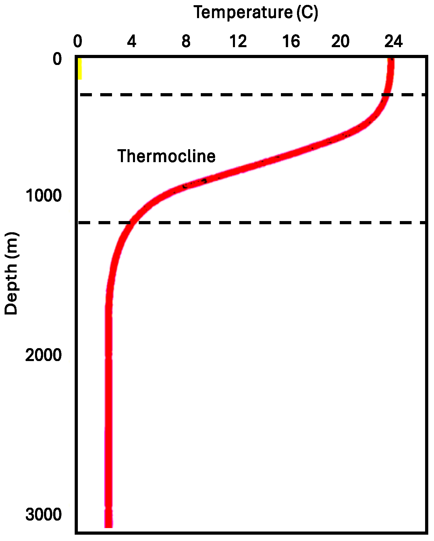
Temperature of Sea Water. Previous investigations show variations in the ocean’s temperature and salinity with latitude [41,42]. The temperatures of the sea surfaces around these oceans are similar. Figure 2 shows an example of variation in ocean water temperature with depth [42]. In low-altitude regions, the surface layer water is an epipelagic zone, also called the sunlight zone, extending from the surface to about 200 m (660 feet). Most of the sunlight is visible in this zone, where the sea surface temperature is as high as 97 °F (36 °C) in the Persian Gulf. In high-altitude regions, the sea surface temperature is as low as 28 °F (−2 °C) near the North Pole. Below the epipelagic zone is the mesopelagic zone (twilight zone or the midwater zone), which extends from about 200 m (660 feet) to about 1000 m (3300 feet). Water temperature decreases rapidly with increasing depth. The depth of the thermocline varies seasonally.
Guo and Mahmood [44] proposed a symmetric model for the seawater temperature profile. The symmetric model was modified in our study to obtain an asymmetric model as follows:
t = t b + t 0 t b 2 2 1 + erf 2 D D m α 1
where t is water temperature at depth of interest in °C, t0 is the seasonal-averaged water temperature at sea surface in °C, tb is the stable water temperature below the mesopelagic zone in °C, erf is Error function, D is water depth of interest in meters, Dm is the water depth at the mid-point of the mesopelagic zone, and a is a tuning factor for asymmetry which is determined by minimizing the root mean square error (RMSE) defined by
E r = 1 n t x , i t m , i 2 n 1
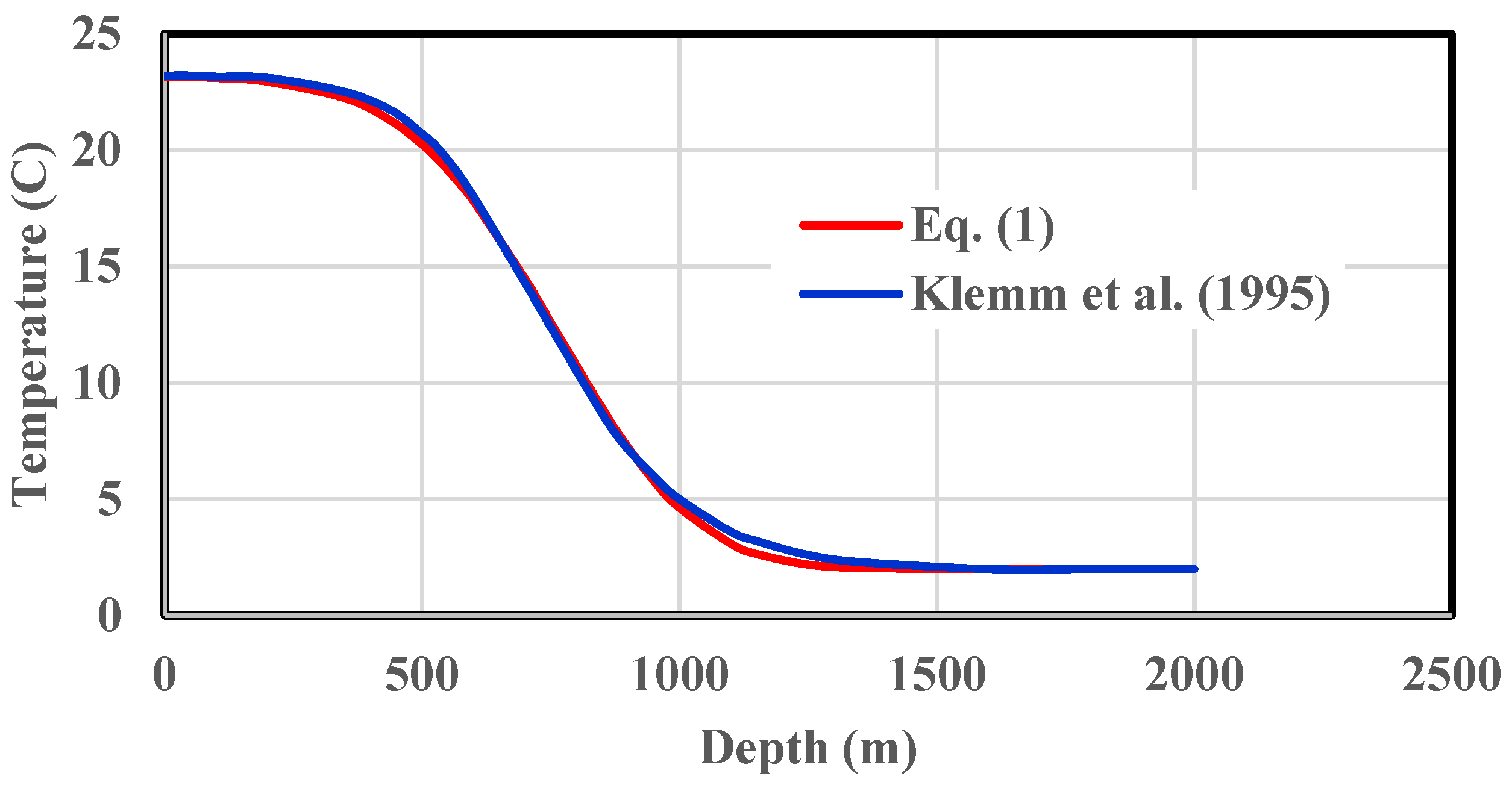
where Er is the RMSE, tx is measured water temperature in °C, tm is modeled water temperature in °C, and n is the number of data points. The RMSE of Equation (1) for the data in Figure 1 was found to be 0.31 with a = 1.19. Figure 3 shows a comparison of the data given in Figure 1 and that by Equation (1).
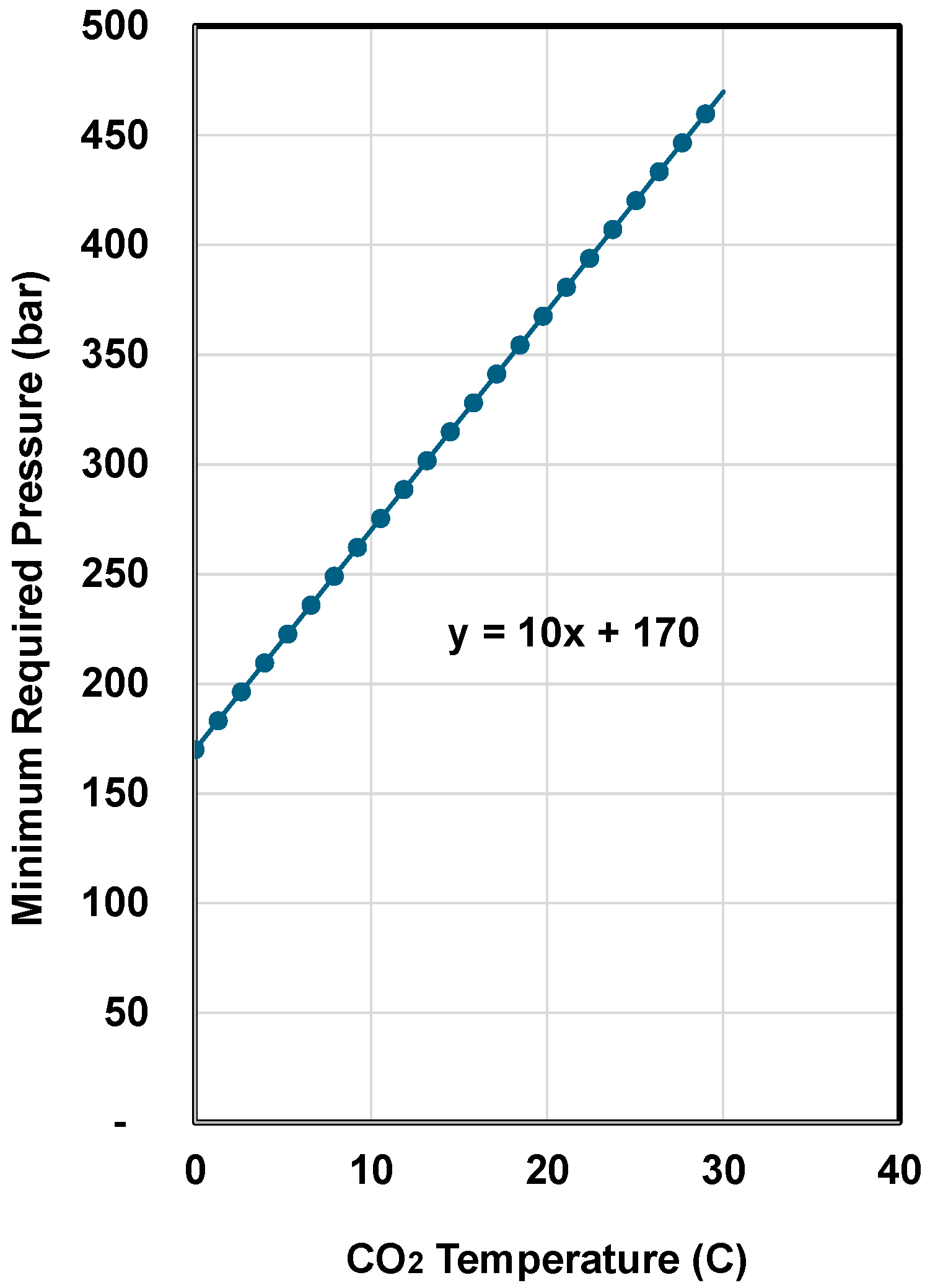
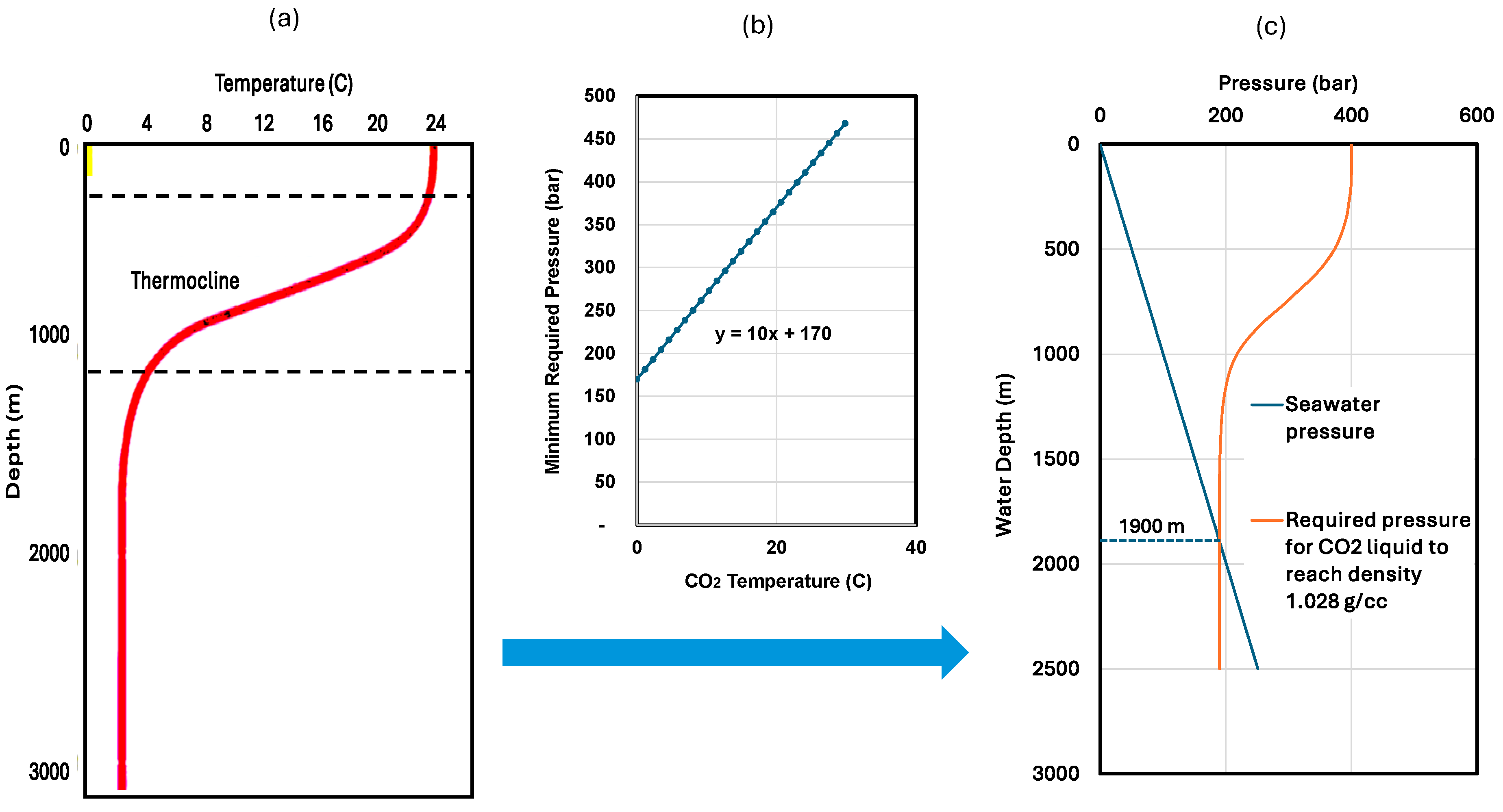
Density of Seawater, CO2 Liquid and CO2 Hydrates. The data presented by Klemm et al. [42] shows that seawater density depends on seawater temperature at a particular depth. Seawater density is determined by the temperature-dependent salinity [41]. It varies in a narrow range between 1.025 g/cc at the sea surface and 1.028 g/cc at depths greater than 1000 m. Calsep [45] shows the density data of CO2 at various pressures and temperatures. Guo and Mahmood [44] presented a chart for the minimum required pressure and the corresponding water depth for CO2 liquid to reach a density of 1.028 g/cc based on the interpolation of data given by Calsep [45]. The chart is partially reproduced and presented in Figure 4.
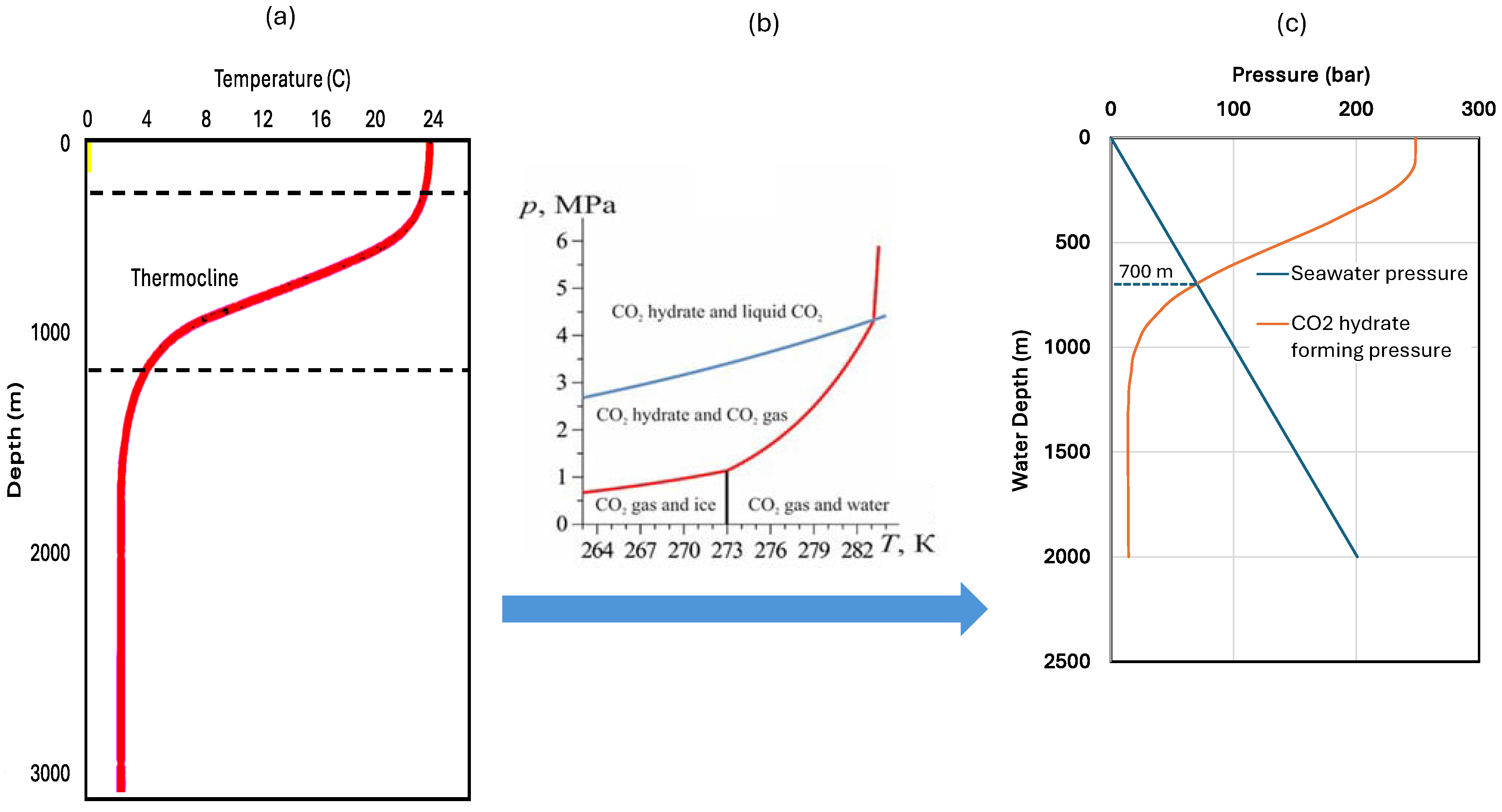
Favorable Seawater Depths for CO2 Disposal. Because CO2 hydrate is always heavier than seawater and liquid CO2 is heavier than seawater in certain pressure conditions, CO2 can be disposed of on the seafloor in both hydrate and liquid forms. Figure 5 illustrates the procedure to determine the minimum seafloor depth for CO2 disposal in hydrate form. The procedure involves plotting the minimum required pressure data for hydrate formation at various seawater depths by combining the data in Figure 1 and Figure 2. Also plotted in the third column graph is the hydrostatic pressure of seawater. The (c)-column graph identifies a curve intersection (cross-over) point at a depth of about 700 m, suggesting that CO2 hydrates should form below a water depth of about 700 m, which is called the critical disposal water depth. It is understood that the minimum required seafloor depth should be greater than the critical disposal water depth. Figure 6 shows the procedure to determine the minimum seafloor depth for CO2 disposal in liquid form. The procedure involves plotting the minimum required pressure data for liquid CO2 formation at various seawater depths by combining the data in Figure 2 and Figure 4. Also plotted in the third column graph is the hydrostatic pressure of seawater. The (c)-column graph identifies a curve intersection (cross-over) point at depth about 700 m, suggesting that CO2 liquid should form below a water depth of about 1900 m, which is called the critical disposal water depth. It is understood that the minimum required seafloor depth should be greater than the critical disposal water depth.

3. Analytical Method

Although the graphical solution method for determining the critical seawater depth is transparent, it takes a lengthy procedure to obtain results. If the curves in these graphs can be described by equations, solving these equations simultaneously should allow a quick solution to the problem. In fact, Kamath [46] gives:
p h = E x p 44.58 10,246 t + 273.15
where ph is the CO2 hydrate-forming pressure in kPa and t is temperature in the range of 0 to 11 °C. The curve in Figure 4 is expressed as
p L = 10 t + 170
where pL is CO2-liquid-forming pressure in bar and t is temperature in °C. The hydrostatic pressure of seawater is expressed by
p s = ρ g D
where ps is the hydrostatic pressure of seawater in Pa, r is density in kg/m3, g is gravitational acceleration (9.81 m/s2), and D is water depth in m.
To predict the CO2 hydrate-forming pressure in a given seawater temperature profile, substituting Equation (1) into Equation (3) gives
p h = E x p 44.58 10,246 t b + t 0 t b 2 2 1 + erf 2 D D m α 1 + 273.15
Equating the right-hand sides of Equations (5) and (6) with unit conversion results in
ρ g D 1000 = E x p 44.58 10,246 t b + t 0 t b 2 2 1 + erf 2 D D m α 1 + 273.15
which can be solved numerically for the critical depth D. For the temperature profile in Figure 2, the numerical solution of Equation (7) for the critical seawater depth is 688 m, which confirms the graphical solution of 700 m given in Figure 5.
To predict the minimum required pressure for forming CO2 liquid of density 1.028 g/cc in a given seawater temperature profile, substituting Equation (1) into Equation (4) gives
p L = 10 t b + t 0 t b 2 2 1 + erf 2 D D m α 1 + 170
Equating the right-hand sides of Equations (5) and (8) with unit conversion results in
ρ g D 100,000 = 10 t b + t 0 t b 2 2 1 + erf 2 D D m α 1 + 170
which can be solved numerically for the critical depth D. For the temperature profile in Figure 2, the numerical solution of Equation (9) for the critical seawater depth is 1893 m, which confirms the graphical solution of 1900 m given in Figure 5.

4. System Requirement

The deposition of CO2 in hydrates on the seafloor below the critical depth requires that CO2 hydrates are formed instantly in seawater unless the water depth is greater than the depth for stable CO2 liquid, where hydrates can form slowly without hydrate floating up. To generate CO2 hydrates instantly, a super-cooling technique is proposed using the Joule–Thomson cooling effect. Figure 7 presents a schematic diagram of a CO2 hydrate generation process using a jet-cooling method. Ship 1 is loaded with liquid CO2 from the carrier connector 2 or pipeline hose to the CO2 tank 3. The liquid CO2 is cooled by cooler 4 to increase its density. The cooled CO2 is pumped by pump 5 into hose 6, leading to the injection head 7, where the CO2 is expanded through the jetting nozzles 8. Due to the Joule-Thomson cooling effect, the jetted CO2 stream should be further cooled below the seawater temperature, causing the formation of CO2 hydrates immediately. The remaining CO2, if any, will form hydrates in the buffer chamber 9. The depth control room 10 receives seawater depth data from the sonar depth surveyor 11 and adjusts the location of the injection head 7 to keep it close to the seafloor. The CO2 monitoring room 12 receives data from the CO2 detector 13 and sends a signal to the CO2 pump control for reducing the CO2 injection rate if free CO2 is detected. The generated CO2 hydrate should remain on the seafloor due to its high density relative to seawater. The ship moves forward slowly as needed.
The total cross-sectional area of the nozzles should be designed to cause a significant pressure drop at the nozzles to generate adequate Joule–Thomson cooling effect. The temperature at the downstream of the nozzles can be estimated based on choke-flow theory [47]:
T d n = T u p z u p z o u t l e t p o u t l e t p u p k 1 k
where zup and zoutlet are compressibility factors at upstream and outlet conditions, poutlet is the pressure at the nozzles’ outlet, pup is the upstream pressure, and k is the specific heat ratio of CO2. The outlet pressure is equal to the sea water pressure in subsonic (subcritical) flow conditions. To achieve the maximum temperature drop, sonic (critical) flow conditions can be used. The critical pressure ratio through the nozzles is expressed as
p o u t l e t p u p c = 2 k + 1 k k 1 ,
where the value of k for CO2 is about 1.28. Thus, the critical pressure ratio is about 0.55 for CO2. This requires that the upstream pressure be more than double that of the downstream pressure, which is the in situ seawater pressure. For example, if the in situ seawater temperature is 276 °K (3 °C), the in situ seawater pressure should be selected to be at least 16.6 bar for hydrate formation. The nozzle size should be designed to create an upstream pressure of at least 13.2 bar for instant hydrate formation. The relationship between the upstream pressure, CO2 flow rate, and total nozzle area can be found in the literature [47].
The following procedure is recommended to design and optimize the performance of the jet-cooling process.
1
Select a seafloor site that is deeper than the critical water depth determined in the procedure shown in Figure 5. Designthe seawater depth for CO2 placement.
2
Calculate the hydrostatic pressure of seawater pdn at the water depth of CO2 placement. This pressure is considered to be the downstream pressure of the jetting nozzles.
3
Calculate the required upstream pressure pup of the jetting nozzles using
p u p = p d n R c
where the critical pressure ratio Rc is given by
R c = 2 k + 1 k k 1
The total area of the nozzles should be designed through the use of the following equation [46]:
q = 879 C A p u p k γ g T u p 2 k + 1 k + 1 k 1
where q is the CO2 flow rate in Mscf/d, C is the nozzle discharge coefficient (close to unity for highly compressed CO2 streams in low-temperature conditions), A is the total cross-sectional area of the nozzles in in2, pup is upstream pressure in psi, γg is the CO2 specific gravity relative to air, and Tup is the CO2 temperature in °R at the upstream of the nozzles (very close to the seawater temperature at the nozzle depth).
To achieve the desired upstream pressure of the nozzles, the surface injection pressure should reach a minimal value given by
p i n j = p u p p h + p f
where pinj is the surface injection pressure, ph is the hydrostatic pressure of the CO2 inside the injection pipe, and pf is the frictional pressure loss of the CO2 inside the injection pipe.

5. Discussion

This study proposes an efficient method and technology suite for the evaluation of safe disposal of CO2 on the seafloors. The proposed process will replace the need for drilling CO2 injection wells by using disposing ships, which should be more economical. However, this document provides an early technical assessment of the process only. Economic analysis is beyond the scope of this document.
Instead of using disposal ships, the proposed idea of CO2 storage in liquid and hydrate forms can be realized using existing subsea structures such as water/CO2 injection wells if the wellheads at the seabed are below the critical disposal water depth. CO2 can be released to the sea floor around the subsea wellheads. However, additional structures/equipment are required to manage hydrate piles, which will incur additional cost.
It is understood that this study does not provide any new data but derives data. The applicability and accuracy of the calculated seawater depths for carbon dioxide disposal are limited by the reliability and accuracy of the input data from the published literature. Significant error in the calculations is not expected. However, it is advised that recalculations are suggested for the researchers and engineers in their location applications.
More research work needs to be conducted to support the engineering design of the system and assess the potential impact of the process on the environment of seafloors. The following work is specially recommended for future focus:
  • Conducting experimental investigations of the proposed jet-cooling process to validate the concept. This is being designed and prepared using a high-pressure–low-temperature windowed cell to observe the settling of CO2 hydrates and CO2 liquid due to gravitational segregation.
  • Performing a quantitative hydrate formation kinetics analysis to determine the minimum required residence time of the jet plume for full solidification under the seawater conditions of the proposed process. This information will be used for designing the geometry (diameter and length) of the buffer chamber to ensure 100% conversion of CO2 to hydrates before the CO2 plume exits the buffer chamber.
  • Carrying out research work to analyze how CO2 liquid and hydrates might be disturbed by bottom sea currents, interact with sediments and nearby man-made structures, warming scenarios of geological events (e.g., earthquake and volcano rupture), extreme weather (e.g., hurricanes and tsunamis), and human activities such as the aviation of artificial objects.
  • It is understood that Equation (1) was established based on the data in Figure 2. Under other seawater conditions, either the actual temperature data from local survey or Equation (1) validated using the actual data should be used to determine the critical water depth for CO2 hydrate formation.
  • Application of the proposed technique is limited to disposal water depths greater than the critical disposal water depths, typically 700 m for storage in hydrate form and 1900 m for storage in liquid form. Local studies need to be conducted in real applications. The major drawback of the technique is that it requires significant investment in building the CO2-disposing ship for CO2 disposal and CO2 carrier for CO2 delivery.

6. Conclusions

An efficient method and technology suite to realize the process for safe disposal of CO2 on the seafloor is presented in this study. The following conclusions are drawn.
  • CO2 can be stored on the seafloor in its liquid-to-hydrate form if the seawater is deep enough. In a typical seawater environment, if the seafloor depth is greater than 6200 ft (1900 m), CO2 can be injected directly onto the seafloor in liquid form. The liquid CO2 will then form hydrates and stay on the seafloor.
  • CO2 can be stored on the seafloor in its hydrate form if the seafloor is deep enough. In a typical seawater environment, if the seafloor depth is greater than 700 m, CO2 can be injected through nozzles to reduce its temperature and generate hydrates. The generated hydrates will then be deposited on the sea floor.
  • The nozzle for reducing the CO2 temperature to generate hydrate is the key component of the proposed technology suite. The nozzles should be sized based on the required upstream pressure and CO2 flow rate. Sonic (critical) flow condition is preferred to maximize the cooling efficiency.

Author Contributions

Conceptualization, B.G.; methodology, M.T.I.; software, V.N.B.A.; validation, B.G.; formal analysis, M.T.I.; investigation, V.N.B.A.; resources, B.G.; data curation, M.T.I.; writing—original draft preparation, V.N.B.A.; writing—review and editing, B.G.; visualization, M.T.I.; supervision, B.G.; project administration, B.G.; funding acquisition, B.G. All authors have read and agreed to the published version of the manuscript.

Funding

This research was funded by BIRD grant number EC-19 and the APC was funded by the Energy Institute of Louisiana at the University of Louisiana at Lafayette.

Data Availability Statement

No new data was created.

Acknowledgments

The authors are grateful to BIRD for funding the project “Safe, sustainable, and resilient development of offshore reservoirs and natural gas upgrading through innovative science and technology: Gulf of Mexico—Mediterranean,” through grant No. EC-19 Fossil Energy.

Conflicts of Interest

The authors declare no conflict of interest.

References

  1. Wei, B.; Wang, B.; Li, X.; Aishan, M.; Ju, Y. CO2 storage in depleted oil and gas reservoirs: A review. Adv. Geo-Energy Res. 2023, 9, 76–93. [Google Scholar] [CrossRef]
  2. Duguid, A.; Guo, B.; Nygaard, R. Well integrity assessment of monitoring wells at an active CO2-EOR flood. Energy Proc. 2017, 114, 5118–5138. [Google Scholar] [CrossRef]
  3. Guo, B. Statistical Analysis of CO2 Exposed Wells to Predict Long Term Leakage Through the Development of an Integrated Neural-Genetic Algorithm; Report to U.S. DOE project DE FE0009284; University of Louisiana at Lafayette: Lafayette, LA, USA, 2017. [Google Scholar]
  4. Li, Q.; Li, Q.; Wang, F.; Xu, N.; Wang, Y.; Bai, B. Settling behavior and mechanism analysis of kaolinite as a fracture proppant of hydrocarbon reservoirs in CO2 fracturing fluid. Colloids Surf. A Physicochem. Eng. Asp. 2025, 724, 137463. [Google Scholar] [CrossRef]
  5. Aoyagi, R. Study on role of simulation of possible leakage from geological CO2 storage in sub-seabed for environmental safety. Energy Procedia 2011, 4, 3881–3888. [Google Scholar] [CrossRef]
  6. University of Oslo. Storage of CO2 in Safe Geological Formations in the Subsurface Can Be an Important Strategy to Reduce CO2 Gasses in the Atmosphere. 19 January 2024. Available online: https://www.mn.uio.no/geo/english/research/groups/co2-storage/index.html (accessed on 1 May 2025).
  7. Ogawa, T.; Nakanishi, S.; Shidahara, T.; Okumura, T.; Hayashi, E. Saline-aquifer CO2 sequestration in Japan-methodology of storage capacity assessment. Int. J. Greenh. Gas Control 2011, 5, 318–326. [Google Scholar] [CrossRef]
  8. Pilisi, N.; Ghorbani, D.; Vasantharajan, S. CO2 Sequestration in Deepwater Sediments Offshore Japan. In Proceedings of the Carbon Management Technology Conference, Orlando, FL, USA, 7–9 February 2012. [Google Scholar] [CrossRef]
  9. JOGMEC. Overview of Request for Proposal on “Business Feasibility Study on Japanese Advanced CCS Project” in FY2023. (30 March 2023). Available online: https://www.jogmec.go.jp/english/news/release/news_10_00036.html (accessed on 15 December 2024).
  10. Anchondo, C. Offshore CO2 Storage Project Nabs $26M DOE Grant. E$E News, 11/19/2024. 2024. Available online: https://www.eenews.net/articles/offshore-co2-storage-project-nabs-26m-doe-grant/ (accessed on 20 April 2025).
  11. Genetti, D. 2024: A Breakout Year for Our Carbon Capture and Storage Business, 9 January 2025. Available online: https://corporate.exxonmobil.com/news/viewpoints/a-breakout-year-for-our-carbon-capture-and-storage-business (accessed on 25 June 2025).
  12. Aramis, 1024. A Large-Scale CO2 Transport and Storage Service. Available online: https://www.aramis-ccs.com/ (accessed on 15 March 2025).
  13. EniSpA. UK Announces the Launch of the Bacton Thames Net Zero Cooperation Agreement. 21 November 2022. Available online: https://www.eni.com/en-IT/media/press-release/2022/11/eni-uk-announces-launch-bacton-thames-net-zero-cooperation-agreement.html (accessed on 12 April 2025).
  14. Ineos. Project Greensand. 2025. Available online: https://www.ineos.com/news/shared-news/ineos-led-greensand-to-become-the-first-full-scale-co2-storage-facility-in-eu-to-help-mitigate-climate-change/ (accessed on 12 April 2025).
  15. L10 CCS. Safe CO2 Storage in the North Sea at Low Cost. Available online: https://l10ccs-storage.com (accessed on 12 April 2025).
  16. CIEL (Center for International Environmental Law). Deep Trouble: The Risks of Offshore Carbon Capture and Storage. CIEL Report (November 2023), Reissued July 2024. Available online: https://www.ciel.org/reports/deep-trouble-the-risks-of-offshore-carbon-capture-and-storage-november-2023/ (accessed on 12 April 2025).
  17. IEEFA; Roberston, B.; Mousavian, M. The Carbon Capture Crux: Lessons Learned, 1 September 2022. Available online: https://www.ieefa.org/resources/carbon-capture-crux-lessons-learned (accessed on 12 April 2025).
  18. IEEFA; Mattei, S.; Schlissel, D. The Ill-Fated Petra Nova CCS Project: NRG Energy Throws in the Towel, 5 October 2023. Available online: https://ieefa.org/resources/ill-fated-petra-nova-ccs-project-nrg-energy-throwstowel (accessed on 12 April 2025).
  19. NETL: Kemper County Energy Facility: Demonstration of a Coal-Based Transport Gasifier, September 2017. Available online: https://www.netl.doe.gov/sites/default/files/netl-file/NT42391.pdf (accessed on 12 April 2025).
  20. Rastelli, E.; Corinaldesi, C.; Dell’Anno, A.; Amaro, T.; Queirós, A.M.; Widdicombe, S.; Danovaro, R. Impact of CO2 leakage from sub-seabed carbon dioxide capture and storage (CCS) reservoirs on benthic virus–prokaryote interactions and functions. Front. Microbiol. 2015, 6, 1–10. [Google Scholar] [CrossRef]
  21. Vinca, A.; Emmerling, J.; Tavoni, M. Bearing the Cost of Stored Carbon Leakage. Front. Energy Res. 2018, 6, 40. [Google Scholar] [CrossRef]
  22. Li, Q.; Han, Y.; Liu, X.; Ansari, U.; Cheng, Y.; Yan, C. Hydrate as a by-product in CO2 leakage during the long-term sub-seabed sequestration and its role in preventing further leakage. Environ. Sci. Pollut. Res. 2022, 29, 77737–77754. [Google Scholar] [CrossRef] [PubMed]
  23. Sloan, E.D.; Koh, C.A. Clathrate Hydrates of Natural Gases; CRC Press: Boca Raton, FL, USA, 2008. [Google Scholar]
  24. Englezos, P.; Kalogerakis, N.; Dholabhai, P. Kinetics of formation of methane and ethane gas hydrates. Chem. Eng. Sci. 1987, 42, 2647–2658. [Google Scholar] [CrossRef]
  25. Skovborg, P.; Rasmussen, P. A mass transport limited model for the growth of methane and ethane gas hydrates. Chem. Eng. Sci. 1994, 49, 1131–1143. [Google Scholar] [CrossRef]
  26. Mohebbi, V.; Naderifar, A.; Behbahani, R. A mass transfer study of methane and ethane during hydrate formation. Pet. Sci. Technol. 2014, 32, 1418–1425. [Google Scholar] [CrossRef]
  27. Kashchiev, D.; Firoozabadi, A. Driving force for crystallization of gas hydrates. J. Cryst. Growth 2002, 241, 220–230. [Google Scholar] [CrossRef]
  28. Vysniauskas, A.; Bishnoi, P. A kinetic study of methane hydrate formation. Chem. Eng. Sci. 1983, 38, 1061–1072. [Google Scholar] [CrossRef]
  29. Natarajan, V.; Bishnoi, P.; Kalogerakis, N. Induction phenomena in gas hydrate nucleation. Chem. Eng. Sci. 1994, 49, 2075–2087. [Google Scholar] [CrossRef]
  30. Cha, M.; Shin, K.; Lee, H.; Moudrakovski, I.L.; Ripmeester, J.A.; Seo, Y. Kinetics of methane hydrate replacement with carbon dioxide and nitrogen gas mixture using in situ NMR spectroscopy. Environ. Sci. Technol. 2015, 49, 1964–1971. [Google Scholar] [CrossRef]
  31. Liu, Q.; Liu, Y.; Xu, J.; Teng, Y.; Ling, Z.; Zhang, Y.; Jiang, L.; Song, Y. A review of the gas hydrate phase transition with a microfluidic approach. Energy Rev. 2023, 2, 100011. [Google Scholar] [CrossRef]
  32. Rahman, M.J.; Fawad, M.; Jahren, J.; Mondol, N.H. Influence of depositional and diagenetic processes on caprock properties of CO2 storage sites in the northern North Sea, offshore Norway. Geosciences 2022, 12, 181. [Google Scholar] [CrossRef]
  33. Brewer, P.G.; Peltzer, E.T.; Walz, P.M.; Coward, E.K.; Stern, L.A.; Kirby, S.H.; Pinkston, J. Deep-Sea Field Test of the CH4 Hydrate to CO2 Hydrate Spontaneous Conversion Hypothesis. Energy Fuels 2014, 28, 7061–7069. [Google Scholar] [CrossRef]
  34. Niu, M.; Yao, Y.; Yin, Z.; Liu, K.; Bian, P.; Zi, M.; Chen, D. Synergistic CH4 hydrate recovery and CO2 storage by coupling depressurization with CO2/N2 injection: A pilot-scale investigation. Chem. Eng. J. 2023, 475, 146216. [Google Scholar] [CrossRef]
  35. Zhou, S.; Li, Q. Construction of self-reliance technology system for development of green ocean energy. Res. Front. 2022, 16, 1–8. [Google Scholar]
  36. University of Texas at Austin. Gulf Coast Ready to Develop Carbon Storage Hub. Phys.Org. 6 July 2021. Available online: https://phys.org/news/2021-07-gulf-coast-ready-carbon-storage.html (accessed on 12 April 2025).
  37. Guo, B.; Zhang, P. Theoretical assessment of CO2 injection into low-temperature water zones for non-leaking storage in hydrate form. Adv. Geo-Energy Res. 2023, 10, 1–6. [Google Scholar] [CrossRef]
  38. Guo, B.; Zhang, P. Injectivity Assessment of Radial-Lateral Wells for CO2 Storage in Marine Gas Hydrate Reservoirs. Energies 2023, 16, 7987. [Google Scholar] [CrossRef]
  39. Guo, B.; Islam, M.; Mahmood, M. Carbon dioxide hydrate formation in porous media under dynamic conditions. Energy Sci. Eng. 2024, 12, 5266–5271. [Google Scholar] [CrossRef]
  40. Mahmood, M.; Guo, B. A Feasibility Study of Using Geothermal Energy to Enhance Natural Gas Production from Offshore Gas Hydrate Reservoirs by CO2 Swapping. Energy Eng. 2023, 120, 2707. [Google Scholar] [CrossRef]
  41. Khasanov, M.K.; Musakaev, N.G.; Stolpovsky, M.V.; Kildibaeva, S.R. Mathematical model of decomposition of methane hydrate during the injection of liquid carbon dioxide into a reservoir saturated with methane and its hydrate. Mathematics 2020, 8, 1482. [Google Scholar] [CrossRef]
  42. Klemm, E.B.; Pottenger, F.M.; Speitel, T.W.; Reed, S.A.; Coopersmith, F.A. The Fluid Earth; Curriculum Research & Development Group: Honolulu, HI, USA, 1990. [Google Scholar]
  43. Klemm, E.B.; Reed, S.A.; Pottenger, F.M.; Porter, C.; Speitel, T.W. The Living Ocean; Curriculum Research & Development Group: Honolulu, HI, USA, 1995. [Google Scholar]
  44. Guo, B.; Mahmood, M.N. Early assessment of carbon dioxide storage on seafloor using jet-cooling technology. J. Environ. Prot. 2025, 16, 695–705. [Google Scholar] [CrossRef]
  45. Calsep. Characterization of CO2 Rich Fluids. Available online: https://calsep.com/23-characterization-of-co2-rich-fluids/ (accessed on 12 April 2025).
  46. Kamath, V.A. Study of Heat Transfer Characteristics During Dissociation of Gas Hydrates in Porous Media. Ph.D. Dissertation, University of Pittsburgh, Ann Arbor, MI, USA, 1984. [Google Scholar]
  47. Guo, B.; Ghalambor, A. Natural Gas Engineering Handbook, 2nd ed.; Gulf Publishing Company: Houston, TX, USA, 2012; pp. 81–85. [Google Scholar]
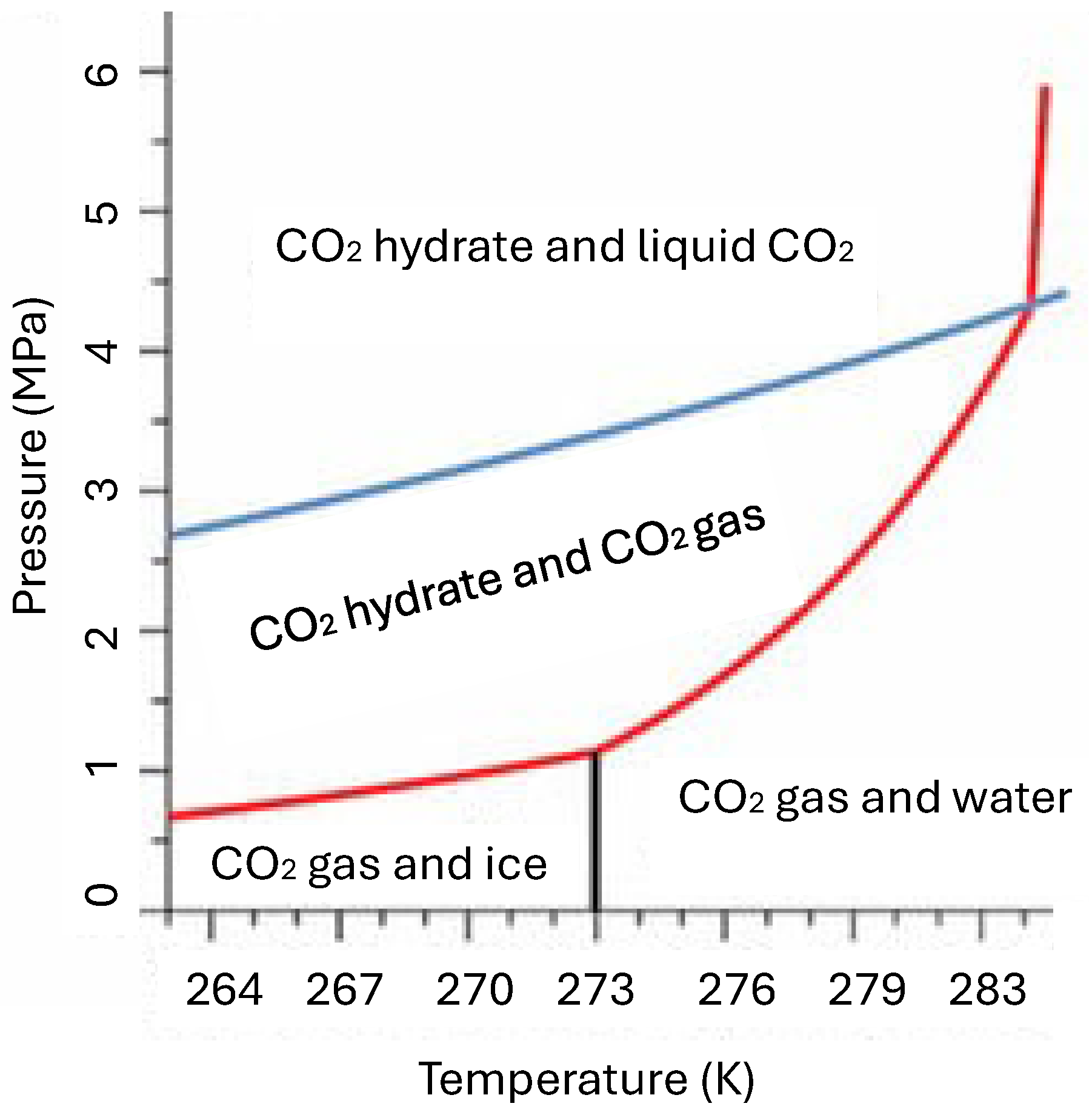
Figure 1. Static conditions for forming CO2 hydrate and methane hydrate [40].
Carbon 11 00081 g001
Figure 2. Variation in ocean water temperature with depth [43].
Carbon 11 00081 g002
Figure 3. Comparison of data given by Klemm [43] and that by Equation (1) with a = 1.19.
Carbon 11 00081 g003
Figure 4. Required pressures at various temperatures for liquid CO2 to reach a density of 1.028 g/cc.
Carbon 11 00081 g004
Figure 5. Procedure for determining the minimum seawater depth of CO2 storage in hydrate form. (a) seawater temperature, (b) hydrate formation pressure, and (c) seawater pressure and hydrate formation pressure.
Carbon 11 00081 g005
Figure 6. Procedure for determining the minimum seawater depth of CO2 storage in liquid form. (a) seawater temperature, (b) liquid CO2 formation pressure, and (c) seawater pressure and liquid CO2 formation pressure.
Carbon 11 00081 g006
Figure 7. A schematic diagram of a CO2 hydrate generation process using a jet-cooling method.
Carbon 11 00081 g007
Disclaimer/Publisher’s Note: The statements, opinions and data contained in all publications are solely those of the individual author(s) and contributor(s) and not of MDPI and/or the editor(s). MDPI and/or the editor(s) disclaim responsibility for any injury to people or property resulting from any ideas, methods, instructions or products referred to in the content.