Abstract
Non-graphitising carbons are an important class of solid carbon materials which cannot be transformed into graphite by heat treatment, even at 3000 °C. Also known as hard carbons, they are of growing importance as anode materials for lithium-ion or sodium-ion batteries. When activated they are widely used in the purification of air and water supplies. However, despite decades of research, the detailed atomic structures of these materials has still not been fully established. Many structural models have been put forward, beginning with the classic work of Rosalind Franklin, but none have gained universal acceptance. This review gives a historical survey of models for the structure of non-graphitising carbons and summarizes the latest thinking on the subject, which is based on the idea that the structure contains non-hexagonal rings, as in the fullerenes and fullerene-related structures. Studies using aberration-corrected transmission electron microscopy have provided important support for this idea.
1. Introduction
In the early 1950s, Rosalind Franklin established that most solid carbon materials could be divided into two categories which she christened ‘graphitising’ and ‘non-graphitising’ [1,2,3]. As the names indicate, graphitising carbons (GCs) can be converted into crystalline graphite by heating to 3000 °C, while non-graphitising carbons (NGCs) cannot. The precursors for GCs include anthracene and polyvinyl chloride (PVC), while materials which produce NGCs include sucrose, polyvinylidene chloride (PVDC) and polyacrylonitrile (PAN). There are some carbon materials which can be considered as intermediate between graphitising and non-graphitising [4], but most pure precursors yield carbons which very clearly fall into one of the two categories. The two forms of carbon have quite different physical properties. Graphitising carbons are comparatively soft and dense materials, while NGCs are hard, with relatively low densities. There are important differences in the porosities of the two forms of carbon. In graphitising carbons the porosity is usually on the scale of 10s or 100s of μm whereas NGCs have pores on the nm scale, which gives them enormously high surface areas. There are two distinct classes of non-graphitising carbons: chars and glassy carbons. Chars are widely used in water and air purification, usually after physical or chemical activation to increase their surface area [5]. They also have a plethora of other applications in fields ranging from medicine [6] to batteries [7]. Glassy carbons are widely used in electrochemistry and as high-temperature crucibles, among other applications [8].
The aim of this review is to give a brief historical survey of models for the structure of graphitising and non-graphitising carbons, from the early ideas of Franklin, which were based largely on X-ray diffraction measurements, to the latest theories, which draw on techniques like aberration-corrected transmission electron microscopy (ACTEM). Firstly, we outline the differences between the structure and properties of graphitising and non-graphitising carbons.
2. Experimental Studies of Graphitising and Non-Graphitising Carbons: Early Work
Here we summarise experimental work on graphitising and non-graphitising carbons carried out from the 1950s to the 1990s. More recent studies using aberration-corrected TEM are discussed in Section 3.4 below.
Franklin’s work involved carbonising a range of organic precursors at 1000 °C and then further heating the carbons at temperatures up to 3000 °C. The structures of the resulting products were then probed using X-ray diffraction. It might be thought that these very high temperature treatments would convert the carbons into crystalline graphite, the most thermodynamically stable form of carbon. However, Franklin found that this was only the case for some of the carbons, for example, those produced from PVC and petroleum coke. The other carbons, including those derived from PVDC and sugar, were not transformed into graphite, even at 3000 °C. Instead, they formed an isotropic, microporous material which only contained tiny regions of graphitic structure.
The effect of heat treatment on graphitising and non-graphitising carbons can be seen in Figure 1, taken from a 1995 X-ray diffraction study by Emmerich [9]. This shows plots of the parameters La and Lc, defined as the length and thickness, respectively, of the graphite domains in the carbons, against temperature. For the graphitising carbon, La reaches a value of ~100 nm at 3000 °C, while for the non-graphitising carbon the maximum value is only ~10 nm. The corresponding values for Lc are ~100 nm and ~4 nm. Only very small graphite crystallites are formed in NGC, even at the highest temperatures.
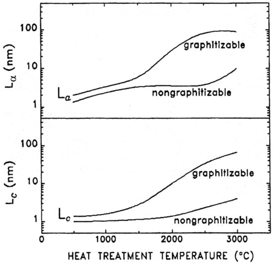
Figure 1.
Variation of La and Lc with heat-treatment temperature for graphitising and non-graphitising carbon. Note that the La and Lc scales are logarithmic. Reproduced with permission from Elsevier, 1995 [9].
Transmission electron microscopy (TEM) has arguably provided the most important insights into the nature of graphitising and non-graphitising carbons. By the early 1970s, improvements in lens design meant that the 0.34 nm interlayer spacing of graphite could be readily resolved [10], and a large number of studies of carbon structure were published in the following years, e.g., [11,12,13,14,15]. In a typical study from 1975, Ban, Crawford and Marsh imaged non-graphitising carbons derived from PVDC which had been heated to temperatures up to 2700 °C [11]. They found that the carbons contained curved graphitic sheets, usually 1, 2 or 3 layers thick, enclosing randomly shaped pores. From this they proposed a ribbon-like model for NGC which is now considered incorrect, as discussed in Section 3.2 below. Extensive TEM studies were also carried out by the Oberlin group, which clearly showed the distinction between the large crystals of graphite produced by heating graphitising carbons and the much more disordered material, containing only tiny graphitic domains, formed from non-graphitising carbon, e.g., [12,13,14]. Also, as noted above, they showed that carbons which could be considered as intermediate between graphitising and non-graphitising were formed from some precursors [4].
Some TEM images of typical non-graphitising and graphitising carbons taken from work by the present author with Burian and Duber are shown in Figure 2 [16]. Figure 2a shows a bright field image of a NGC prepared from sucrose at 1000 °C, with an inset showing a diffraction pattern recorded from the same sample. The image shows that the structure is isotropic and highly disordered, with no obvious graphitisation. The symmetrical rings of the diffraction pattern confirm the isotropic structure. The structure of the anthracene-derived graphitising carbon, shown in Figure 2b, approximates much more closely to that of graphite in that it consists of small, approximately flat layers, packed closely together with a high degree of alignment. For this carbon the diffraction pattern consists of arcs rather than rings, confirming the preferential alignment of the layers.
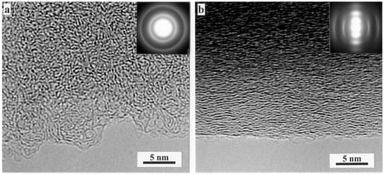
Figure 2.
(a) High resolution TEM image of carbon prepared by pyrolysis of sucrose in nitrogen at 1000 °C. (b) Carbon prepared by pyrolysis of anthracene at 1000 °C. Insets show selected area diffraction patterns. Reproduced with permission from Taylor & Francis, 2000 [16].
The effect of high-temperature heat treatments on the structure of non-graphitising and graphitising carbons is shown in the images reproduced in Figure 3 [17]. For the non-graphitising carbon, heating at a temperature of 2300 °C in an inert atmosphere produces the porous disordered material shown in Figure 3a. This is made up of faceted and curved graphitic layers, typically ~1–2 nm thick and 5–10 nm in length, enclosing irregularly shaped pores. There is no large-scale graphitisation here. By contrast, heat treatment of the graphitising carbon produces large crystals of well-ordered graphite, as shown in Figure 3b. Detailed examination of heat-treated non-graphitising carbons by TEM showed that they often contained fullerene-like features, such as completely closed particles, and this led the present author and Tsang to propose a fullerene-related structure for non-graphitising carbon [18], as discussed in Section 3.4, below.
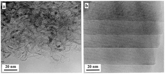
Figure 3.
TEM images of (a) sucrose carbon and (b) anthracene carbon following heat treatment at 2300 °C. Reproduced with permission from Taylor & Francis, 2005 [17].
3. Structural Models of Non-Graphitising Carbons
3.1. The Models of Franklin
Franklin described her studies of graphitisation in a paper for the Proceedings of the Royal Society of London, published in 1951 [1]. She proposed models for the two classes of material she had identified; these are shown in Figure 4. The basic units in these structures are small graphitic domains joined together by crosslinks. In the model of graphitising carbon, the graphitic domains are approximately parallel to each other, and the crosslinks are assumed to be weak as in Figure 4a. Such a structure would be relatively easy to transform into crystalline graphite. By contrast, the structure of non-graphitising carbons consists of randomly oriented domains as in Figure 4b, and the cross-links are strong enough to impede movement of the layers into a parallel arrangement. While these models do not represent a full description of the distinction between graphitising and non-graphitising carbons, since the nature of the cross-links is not explained, they have in fact stood the test of time rather better than some of the other models that have been proposed for NGCs.
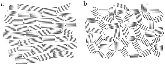
Figure 4.
Franklin’s models of (a) graphitising carbon and (b) non-graphitising carbon. Reproduced from [1].
3.2. The Models of Ban, Crawford and Marsh
As noted above, in the mid 1970s, Ban, Crawford and Marsh put forward ribbon-like models for non-graphitising carbons, based on their TEM studies [11]. One of their models, intended to represent a PVDC-derived carbon heated at 1950 °C, is shown in Figure 5. A similar model for the structure of glassy carbon had been proposed in 1971 by Jenkins and Kawamura [19]. However, models of this kind have serious deficiencies. The models assume a structure in which twisted and curved and graphite ribbons, typically made up of 2–3 layers, enclose randomly shaped pores. A problem with this is that thin graphite sheets of this kind are known to be flexible, so that the structure would tend to collapse at high temperatures, in order to reduce surface energy. There are many examples in the literature of tightly folded graphene and graphite sheets in carbons that have been exposed to high temperatures, e.g., [20]. Thus, structures like the one shown in Figure 5 would be unlikely to be stable at very high temperatures.
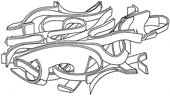
Figure 5.
Model of a PVDC-derived carbon heat treated at 1950 °C, from work by Ban, Crawford and Marsh. Reproduced with permission from International Union of Crystallography, 1975 [11].
Quite apart from their inherent instability, the ribbon-like models of Ban et al. were in fact based on a dubious interpretation of the electron micrographs, as pointed out by Oberlin [14]. In most TEM images of graphitic carbons, only the {002} lattice planes are resolved, and these are visible only when they are close to being parallel to the electron beam. Layers even slightly tilted away from this condition will not be visible. This results in images of graphitic carbons having a ribbon-like appearance, when in reality, the true 3-dimensional structure may be more cage-like than ribbon-like. This should always be borne in mind when analyzing TEM images of graphitic carbons.
3.3. The Theories of Oberlin and Colleagues
As already mentioned, from the 1960s onwards Oberlin and colleagues carried out extensive studies of carbons and graphites using TEM and other techniques, e.g., [4,12,13,14,21]. This led them to develop detailed theories of carbonisation, graphitisation and the structure of graphitising and non-graphitising carbons, which will now be summarised.
In the first stage of carbonisation, the precursor begins to lose elements other than carbon. Simultaneously, polyaromatisation and polycondensation reactions occur, creating basic structural units (BSUs). These are small graphenic domains consisting of planes roughly 0.7–1 nm in size, typically in stacks of 1–3. At some temperature, which depends on the precursor, the material becomes more or less fluid, which may result in the BSUs becoming more aligned with each other. In materials with few cross-linking groups, the viscosity is low enough for the BSUs to align in large domains, known as regions of local molecular orientation (LMO). This results in a graphitising carbon. However, in precursors which contain O, N and S, significant cross-linking may occur, resulting in high viscosity. In such cases little alignment of BSUs occurs, giving small LMO domains and producing a non-graphitising carbon. At a temperature in the range 400–550 °C, the material solidifies again; this is the end of what Oberlin called primary carbonisation. As the temperature increases, so-called secondary carbonisation takes place. For graphitising carbons this involves the removal of remaining non-carbon atoms and increasing alignment of BSUs within the LMOs. For non-graphitising carbons, a structure consisting of pores bounded by randomly oriented regions derived from the LMOs is formed. A sketch of this structure is shown in Figure 6. The process of secondary carbonisation is complete at ~1800–2000 °C. To summarise Oberlin’s view, the ability of a carbon to graphitize is entirely determined by the size of the elemental domains in the bulk mesophase.
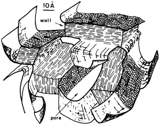
Figure 6.
Oberlin’s model for a non-graphitising carbon heated to ‘graphitising’ temperature. Reproduced with permission from Elsevier, 1982 [22].
In recent years Ouzilleau and Monthioux have extended Oberlin’s approach to graphitisablity by considering the thermodynamics of the process [23]. Their work will not be discussed in detail here, but essentially, they consider the structural evolution of graphitising and non-graphitising carbons following the end of primary carbonisation. At this point the carbons consist of LMOs separated by mesoscale grain boundaries (mGBs) and arranged around a central pore. For graphitising carbons this is a mesopore, for non-graphitising carbons a micropore. The LMOs are assumed to consist of two phases: intercrystalline matter and coke crystallites. Considering first graphitising carbons, the model assumes that, with increasing temperature, the LMOs in the initial structure coalesce, producing some annealable topological defects (ATDs) at the interfaces. At a critical temperature of around 2300 °C, the intercrystalline matter and coke crystallites merge to form a single body. Then, with further heat-treatment to around 3000 °C, the ATDs will be annealed out, eventually leading to perfect crystalline graphite. For non-graphitising carbons, a similar path is followed up to the point of the formation of the topological defects, but in this case the defects are not destroyed by further heat treatment so that crystalline graphite is not formed.
3.4. Fullerene-Related Models
The discovery of C60 and other fullerenes [24,25] and later of related structures such as carbon nanotubes [26] gave us a new perspective on the structure of solid carbon. These new structures contained pentagonal carbon rings, as well as other non-six-membered rings, among the hexagonal sp2 carbon network, and in many cases were highly stable. This prompted a number of authors to consider whether well-known forms of carbon might also contain non-hexagonal rings. The idea that non-graphitising carbon might containing fullerene-like structures was suggested by the present author and Tsang in 1997 [18] and elaborated in a series of further papers [16,17,27,28,29]. The ‘random schwarzite’ structure put forward in 1992 by Townsend et al. [30] is sometimes cited as a model for non-graphitising carbon. This is a negatively curved continuous network, intended to represent the structure of amorphous carbon; it does not seem appropriate for non-graphitising carbons. The model proposed by the present author and Tsang was inspired by a detailed examination of TEM images of heat-treated non-graphitising carbons, specifically chars prepared from PVDC and sucrose. A typical micrograph of such a carbon at moderate magnification is shown in Figure 3a. Higher magnification images showed that the carbon often contained completely closed nanoparticles, typically around 5–10 nm in size; examples are shown in Figure 7. The particles tended to be faceted and were often hexagonal or pentagonal in shape. In some cases, saddle-points could be seen (arrowed in Figure 7b), indicating the presence of heptagonal rings, as suggested by Iijima et al. in their study of nanotube caps [31]. The presence of seemingly fullerene-related features in the heat-treated carbons suggested that the ‘fresh’ carbons may also have had fullerene-like structures, and that the presence of these structures impeded graphitisation. A fullerene-related model for char was therefore put forward in the 1997 paper [18]. The model consisted of discrete carbon fragments which exhibited random curvature as a result of the presence of pentagonal and heptagonal rings dispersed throughout the hexagonal sp2 network. In the original model, the fragments only contained around 100 carbon atoms. A more realistic model of char, with rather larger fragments, is shown in Figure 8. It should be noted that this is simply an illustration intended to show the structures of individual fragments rather than a 3-dimensional model. In the 3-dimensional structure, the fragments would overlap with each other and be more closely packed together. Also, the edge atoms would be decorated with hydrogens or oxygen-containing functional groups rather than simple terminations of the carbon networks. It may be asked how the structure shown in Figure 8 holds together and does not simply fall apart. The probable explanation is that the fragments are held together by van der Waals forces like those which bind C60 molecules together in fullerite crystals.
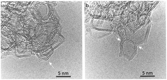
Figure 7.
(a) Micrograph showing closed structure in PVDC-derived carbon heated at 2600 °C. Arrow shows closed particle. (b) Another micrograph of same sample, with arrows showing regions of negative curvature. Reproduced with permission from Taylor & Francis, 1997 [18].
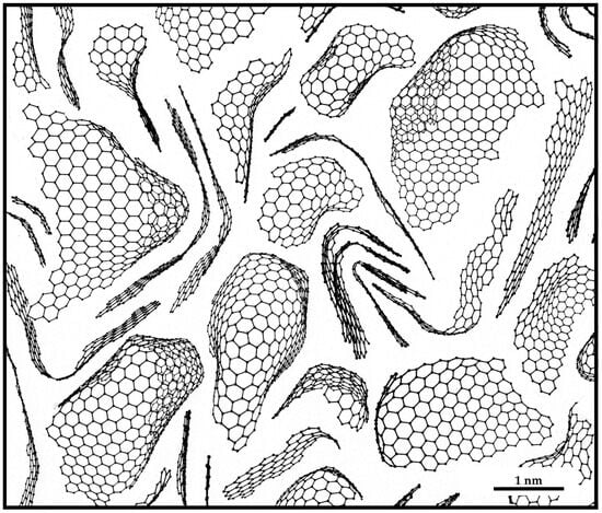
Figure 8.
Model of char made up of fragments containing pentagons and heptagons dispersed throughout hexagonal sp2 networks.
Models for the structure of chars which incorporate non-hexagonal rings have been developed by other groups. For example, McDonald-Wharry et al. presented a model in 2016 which combined features from both Franklin’s and Oberlin’s theories with the presence of pentagonal and heptagonal rings [32], while in 2024, Erastova and co-workers developed models which were tailored to represent the structure of biochar derived from wood [33].
The most direct evidence for the presence of non-hexagonal rings in chars comes from studies using aberration-corrected transmission electron microscopes [34,35,36]. The first study of this type was carried out by the present author with Liu and Suenaga in 2008 [34]. This involved using an ACTEM to image a commercial activated carbon, Norit GSX. Although it was not possible in this study to obtain clear images of the atomic structure of the fresh carbon, images of carbon which had been heated to 2000 °C did show clear evidence for the presence of pentagonal rings. In another study by Guo et al., published in 2012, annular dark-field scanning transmission electron microscopy (ADF-STEM) was used to image two carbons: a wood-derived high surface area activated carbon and a lower surface area non-activated carbon obtained by pyrolysis of poly (furfuryl alcohol) [35]. They found that in both cases the carbon consisted of puckered graphene sheets composed mostly of hexagonal rings, but with a significant number of non-hexagonal rings (pentagons and heptagons) which often formed chains, as can be seen in Figure 9a,b. Based on these results, Guo et al. put forward the model illustrated in Figure 9c,d.
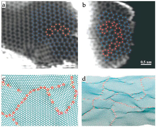
Figure 9.
(a,b) ADF-STEM images of wood-derived ultramicroporous carbon. Hexagonal rings marked in blue, pentagonal and heptagonal rings marked in red. (c,d) Defective graphene sheet models of carbon structure based on micrographs shown above. Reproduced with permission from Wiley, 2012 [35].
A further ACTEM study was published in 2022 by the present author with Allen, Ghamouss and Boujibar [36]. In this work, a highly activated carbon with a very open structure was imaged in an aberration-corrected TEM operated at 80 keV. Figure 10a shows one of the images from this work. This region contains two pentagonal rings in the area outlined in red. Note that the bright spots here represent the centres of the carbon rings. Figure 10b,c shows this area at higher magnification, with the red dots in Figure 10c indicating the centres of the pentagonal rings and the hexagonal rings surrounding them. Figure 10d is an image simulation of the structure in Figure 10e and is in reasonable agreement with the experimental images. Other images of the same sample showed clear evidence of heptagonal rings. As well as the TEM images, some ADF-STEM images were recorded in this study, and these confirmed the presence of non-hexagonal rings. Drawing on these results, the authors put forward the model for the structure of activated carbon shown in Figure 11. This is similar to the char model shown in Figure 8 but with the smaller fragments removed. Interestingly, this model predicts a bimodal distribution of pore sizes, with the curved fragments enclosing pores of the order of 2 nm in size (indicated by blue arrow) and narrow, sub-nm slit-like pores between the fragments (red arrow). Bimodal distributions are observed experimentally in some carbons, as discussed by Gauden et al. [37].
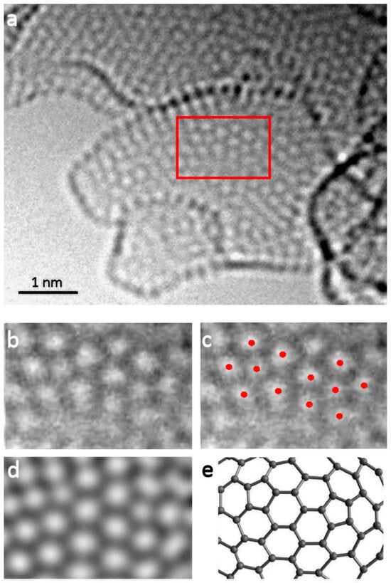
Figure 10.
(a) AC-TEM bright-field image of region of activated carbon containing pentagonal rings, (b) enlarged image of area containing pentagons, (c) image with red dots highlighting positions of ring centres, (d) simulated image of structure shown in (e). Reproduced with permission from Royal Society, 2022 [36].
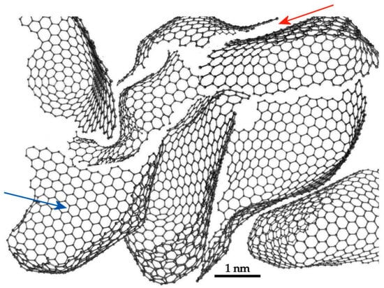
Figure 11.
Model of activated carbon made up of fullerene-related fragments. Arrows indicate two different kinds of pores: blue arrow indicates randomly-shaped, three-dimensional pore, red arrow indicates slit-like pore. Adapted with permission from Royal Society, 2022 [36].
Although not discussed here, glassy carbons may also have structures related to those of the fullerenes, as discussed by several authors [38,39,40]. Finally, it should be noted that, in addition to TEM, other techniques, including Raman [41] and electron energy loss spectroscopy [42] have provided evidence that NGC might contain fullerene-like structures.
4. Discussion and Suggestions for Further Work
The idea that non-graphitising carbons have a structure containing non-hexagonal rings continues to gain experimental support, particularly from studies using aberration-corrected TEM. This does not of course invalidate the early work of Franklin and others, who were simply not aware that non-hexagonal rings, dispersed in a hexagonal sp2 carbon network, could be highly stable. On the other hand, some of the early models, such as that shown in Figure 5, are definitely incorrect and based on a misinterpretation of conventional TEM images. While ACTEM images have provided clear evidence of pentagonal and heptagonal rings in non-graphitising carbons, there is disagreement about the precise structure of the carbons. The two detailed ACTEM studies of NGCs published to date [35,36] led to rather different structural models, illustrated in Figure 9c,d and Figure 11. There is clearly a need for more studies of this kind in order to establish which of the models is closest to the true structure.
If a fullerene-like model for non-graphitising carbon is correct, this raises the interesting question of why some carbonaceous precursors produce carbons containing non-hexagonal rings while others do not. It is possible that the answer may lie in the chemistry of the precursors. The importance of chemical composition in determining which kind of carbon is formed was first demonstrated by Franklin [1], who showed that NGCs are formed, in general, from precursors ‘containing little hydrogen or much oxygen’, while graphitising carbons are formed, in general, from precursors ‘containing much hydrogen’. This was confirmed in the studies of Oberlin et al. mentioned in Section 3.3 [12,13,14]. There were exceptions to this, however, even in Franklin’s own work: for example, PVDC, which contains no oxygen, forms a non-graphitising carbon. Nevertheless, it remains the case that O-containing precursors tend to produce non-graphitising carbons. Is there any reason to believe that the presence of O in a carbonaceous material might promote pentagon (or heptagon) formation on carbonisation? This question was considered in the paper by McDonald-Wharry et al. mentioned above [32]. In their discussion they cited work by Homann on the formation of fullerenes in flames, in which it was suggested that the removal of O in the form of CO from partially oxidized polyaromatic hydrocarbons could result in the formation of pentagonal rings [43]. The idea that a similar pentagon formation mechanism might occur during the carbonisation of oxygen-containing precursors seems worth considering. Theoretical work on the oxidation of chars may also be relevant here. Radovic and colleagues also showed that the removal of O from molecules containing hexagonal carbon rings can result in the formation of pentagons [44]. Although Radovic et al. are modelling C oxidation in this work, rather than the carbonisation of an O-containing precursor, it is possible that a similar mechanism might be involved in both processes. In general, carbonisation remains a rather poorly understood process; more work is clearly needed to understand how the chemistry of the precursor affects the structure of the final carbon.
One final area where more work would be welcome is in using models like that shown in Figure 11 to predict the adsorptive behaviour of activated carbons. A few such studies have been published, e.g., [45,46,47,48], and these have generally found good agreement between experimental results and simulations carried out using fullerene-like models. However, the models used were made up of unrealistically small fragments. More studies of this kind using larger fragments are needed.
Funding
This research received no external funding.
Institutional Review Board Statement
Not applicable.
Data Availability Statement
No new data were created or analyzed in this study.
Conflicts of Interest
The author declares no conflicts of interest.
References
- Franklin, R.E. Crystallite Growth in Graphitizing and Non-Graphitizing Carbons. Proc. R. Soc. Lond. 1951, 209, 196–218. [Google Scholar]
- Harris, P.J.F. Rosalind Franklin’s Work on Coal, Carbon, and Graphite. Interdiscip. Sci. Rev. 2001, 26, 204–210. [Google Scholar] [CrossRef]
- The Rosalind Franklin Papers. Available online: https://profiles.nlm.nih.gov/spotlight/kr/feature/coal (accessed on 3 October 2025).
- Monthioux, M.; Oberlin, M.; Oberlin, A.; Bourrat, X.; Boulet, R. Heavy Petroleum Products: Microtexture and Ability to Graphitize. Carbon 1982, 20, 167–176. [Google Scholar] [CrossRef]
- Reza, M.S.; Yun, C.S.; Afroze, S.; Radenahmad, N.; Bakar, M.S.A.; Saidur, R.; Taweekun, J.; Azad, A.K. Preparation of Activated Carbon from Biomass and Its Applications in Water and Gas Purification, a Review. Arab. J. Basic Appl. Sci. 2020, 27, 208–238. [Google Scholar] [CrossRef]
- Mechnou, I.; Benabdallah, A.; Chham, A.-I.; Rachdi, Y.; Hlaibi, M.; El kartouti, A.; Saleh, N. Activated Carbons for Effective Pharmaceutical Adsorption: Impact of Feedstock Origin, Activation Agents, Adsorption Conditions, and Cost Analysis. Results Eng. 2025, 27, 105966. [Google Scholar] [CrossRef]
- Pei, B.; Yu, H.; Zhang, L.; Fang, G.; Zhou, J.; Cao, X.; Liang, S. Hard Carbon for Sodium-Ion Batteries: From Fundamental Research to Practical Applications. Adv. Mater. 2025, 2504574. [Google Scholar] [CrossRef]
- de Souza Vieira, L. A Review on the Use of Glassy Carbon in Advanced Technological Applications. Carbon 2022, 186, 282–302. [Google Scholar] [CrossRef]
- Emmerich, F.G. Evolution with Heat Treatment of Crystallinity in Carbons. Carbon 1995, 33, 1709–1715. [Google Scholar] [CrossRef]
- Williams, D.B.; Carter, C.B. Transmission Electron Microscopy: A Textbook for Materials Science, 2nd ed.; Springer: New York, NY, USA, 2009. [Google Scholar]
- Ban, L.L.; Crawford, D.; Marsh, H. Lattice-Resolution Electron Microscopy in Structural Studies of Non-Graphitizing Carbons from Polyvinylidene Chloride (PVDC). J. Appl. Cryst. 1975, 8, 415–420. [Google Scholar] [CrossRef]
- Oberlin, A.; Terriere, G. Graphitization Studies of Anthracites by High Resolution Electron Microscopy. Carbon 1975, 13, 367–376. [Google Scholar] [CrossRef]
- Oberlin, A. Carbonization and Graphitization. Carbon 1984, 22, 521–541. [Google Scholar] [CrossRef]
- Oberlin, A. High-Resolution TEM Studies of Carbonization and Graphitization. In Chemistry and Physics of Carbon; Thrower, P.A., Ed.; Marcel Dekker Inc.: New York, NY, USA, 1989; Volume 22, p. 1. [Google Scholar]
- Millward, G.R.; Jefferson, D.A. Lattice Resolution of Carbons by Electron Microscopy. In Chemistry and Physics of Carbon; Walker, P.L., Jr., Thrower, P.A., Eds.; Marcel Dekker Inc.: New York, NY, USA, 1978; Volume 14, p. 1. [Google Scholar]
- Harris, P.J.F.; Burian, A.; Duber, S. High-Resolution Electron Microscopy of a Microporous Carbon. Phil. Mag. Lett. 2000, 80, 381–386. [Google Scholar] [CrossRef]
- Harris, P.J.F. New Perspectives on the Structure of Graphitic Carbons. Crit. Rev. Solid State Mater. Sci. 2005, 30, 235–253. [Google Scholar] [CrossRef]
- Harris, P.J.F.; Tsang, S.C. High-Resolution Electron Microscopy Studies of Non-Graphitizing Carbons. Phil. Mag. B 1997, 76, 667–677. [Google Scholar] [CrossRef]
- Jenkins, G.M.; Kawamura, K. Structure of Glassy Carbon. Nature 1971, 231, 175–176. [Google Scholar] [CrossRef] [PubMed]
- Buseck, P.R.; Huang, B.; Keller, L.P. Electron Microscope Investigation of the Structures of Annealed Carbons. Energy Fuels 1987, 1, 105–110. [Google Scholar] [CrossRef]
- Monthioux, M. Describing Carbons. Carbon Trends 2024, 14, 100325. [Google Scholar] [CrossRef]
- Bonijoly, M.; Oberlin, M.; Oberlin, A. A Possible Mechanism for Natural Graphite Formation. Int. J. Coal Geol. 1982, 1, 283–312. [Google Scholar] [CrossRef]
- Ouzilleau, P.; Gheribi, A.E.; Chartrand, P.; Soucy, G.; Monthioux, M. Why some carbons may or may not graphitize? The point of view of thermodynamics. Carbon 2019, 149, 419–435. [Google Scholar] [CrossRef]
- Kroto, H.W.; Heath, J.R.; O’Brien, S.C.; Curl, R.F.; Smalley, R.E. C60: Buckminsterfullerene. Nature 1985, 318, 162–163. [Google Scholar] [CrossRef]
- Krätschmer, W.; Lamb, L.D.; Fostiropoulos, K.; Huffman, D.R. Solid C60: A New Form of Carbon. Nature 1990, 347, 354–358. [Google Scholar] [CrossRef]
- Iijima, S. Helical Microtubules of Graphitic Carbon. Nature 1991, 354, 56–58. [Google Scholar] [CrossRef]
- Harris, P.J.F. Structure of Non-Graphitising Carbons. Int. Mater. Rev. 1997, 42, 206–218. [Google Scholar] [CrossRef]
- Harris, P.J.F. Fullerene-like Models for Microporous Carbon. J. Mater. Sci. 2013, 48, 565–577. [Google Scholar] [CrossRef]
- Harris, P.J.F. Non-Graphitizing Carbon: Its Structure and Formation from Organic Precursors. Eurasian Chem.-Technol. J. 2019, 21, 227–234. [Google Scholar] [CrossRef]
- Townsend, S.J.; Lenosky, T.J.; Muller, D.A.; Nichols, C.S.; Elser, V. Negatively Curved Graphitic Sheet Model of Amorphous Carbon. Phys. Rev. Lett. 1992, 69, 921–924. [Google Scholar] [CrossRef]
- Iijima, S.; Ichihashi, T.; Ando, Y. Pentagons, Heptagons and Negative Curvature in Graphite Microtubule Growth. Nature 1992, 356, 776–778. [Google Scholar] [CrossRef]
- McDonald-Wharry, J.S.; Manley-Harris, M.; Pickering, K.L. Reviewing, Combining, and Updating the Models for the Nanostructure of Non-Graphitizing Carbons Produced from Oxygen-Containing Precursors. Energy Fuels 2016, 30, 7811–7826. [Google Scholar] [CrossRef]
- Wood, R.; Mašek, O.; Erastova, V. Developing a Molecular-Level Understanding of Biochar Materials Using Public Characterization Data. Cell Rep. Phys. Sci. 2024, 5, 102036. [Google Scholar] [CrossRef]
- Harris, P.J.F.; Liu, Z.; Suenaga, K. Imaging the Atomic Structure of Activated Carbon. J. Phys. Condens. Matter 2008, 20, 362201. [Google Scholar] [CrossRef]
- Guo, J.; Morris, J.R.; Ihm, Y.; Contescu, C.I.; Gallego, N.C.; Duscher, G.; Pennycook, S.J.; Chisholm, M.F. Topological Defects: Origin of Nanopores and Enhanced Adsorption Performance in Nanoporous Carbon. Small 2012, 8, 3283–3288. [Google Scholar] [CrossRef]
- Allen, C.S.; Ghamouss, F.; Boujibar, O.; Harris, P.J.F. Aberration-Corrected Transmission Electron Microscopy of a Non-Graphitizing Carbon. Proc. R. Soc. A Math. Phys. Eng. Sci. 2022, 478, 20210580. [Google Scholar] [CrossRef]
- Gauden, P.A.; Terzyk, A.P.; Jaroniec, M.; Kowalczyk, P. Bimodal Pore Size Distributions for Carbons: Experimental Results and Computational Studies. J. Colloid Interface Sci. 2007, 310, 205–216. [Google Scholar] [CrossRef] [PubMed]
- Harris, P.J.F. Fullerene-Related Structure of Commercial Glassy Carbons. Philosophical Magazine 2004, 84, 3159–3167. [Google Scholar] [CrossRef]
- Jurkiewicz, K.; Duber, S.; Fischer, H.E.; Burian, A. Modelling of Glass-like Carbon Structure and Its Experimental Verification by Neutron and X-Ray. J. Appl. Crystallogr. 2017, 50, 36–48. [Google Scholar] [CrossRef]
- Sharma, S.; Zorzi, S.; Cristiglio, V.; Schweins, R.; Mondelli, C. Quantification of Buckminsterfullerene (C60) in Non-Graphitizing Carbon and a Microstructural Comparison of Graphitizing and Non-Graphitizing Carbon via Small Angle Neutron Scattering. Carbon 2022, 189, 362–368. [Google Scholar] [CrossRef]
- Burian, A.; Daniel, P.; Duber, S.; Dore, J. Raman Scattering Studies of the Graphitization Process in Anthracene- and Saccharose-Based Carbons. Philos. Mag. B 2001, 81, 525–540. [Google Scholar] [CrossRef]
- Zhang, Z.; Brydson, R.; Aslam, Z.; Reddy, S.; Brown, A.; Westwood, A.; Rand, B. Investigating the Structure of Non-Graphitising Carbons Using Electron Energy Loss Spectroscopy in the Transmission Electron Microscope. Carbon 2011, 49, 5049–5063. [Google Scholar] [CrossRef]
- Homann, K.H. Fullerenes and Soot Formation— New Pathways to Large Particles in Flames. Angew. Chem. Int. Ed. 1998, 37, 2434–2451. [Google Scholar] [CrossRef]
- Vallejos-Burgos, F.; Díaz-Pérez, N.; Silva-Villalobos, Á.; Jiménez, R.; García, X.; Radovic, L.R. On the Structural and Reactivity Differences between Biomass- and Coal-Derived Chars. Carbon 2016, 109, 253–263. [Google Scholar] [CrossRef]
- Terzyk, A.P.; Furmaniak, S.; Gauden, P.A.; Harris, P.J.F.; Włoch, J.; Kowalczyk, P. Hyper-Parallel Tempering Monte Carlo Simulations of Ar Adsorption in New Models of Microporous Non-Graphitizing Activated Carbon: Effect of Microporosity. J. Phys. Condens. Matter 2007, 19, 406208. [Google Scholar] [CrossRef]
- Di Biase, E.; Sarkisov, L. Systematic Development of Predictive Molecular Models of High Surface Area Activated Carbons for Adsorption Applications. Carbon 2013, 64, 262–280. [Google Scholar] [CrossRef]
- Sarkisov, L.; Centineo, A.; Brandani, S. Molecular Simulation and Experiments of Water Adsorption in a High Surface Area Activated Carbon: Hysteresis, Scanning Curves and Spatial Organization of Water Clusters. Carbon 2017, 118, 127–138. [Google Scholar] [CrossRef]
- Yin, C.-Y.; Ng, M.-F.; Saunders, M.; Goh, B.-M.; Senanayake, G.; Sherwood, A.; Hampton, M. New Insights into the Adsorption of Aurocyanide Ion on Activated Carbon Surface: Electron Microscopy Analysis and Computational Studies Using Fullerene-like Models. Langmuir 2014, 30, 7703–7709. [Google Scholar] [CrossRef] [PubMed]
Disclaimer/Publisher’s Note: The statements, opinions and data contained in all publications are solely those of the individual author(s) and contributor(s) and not of MDPI and/or the editor(s). MDPI and/or the editor(s) disclaim responsibility for any injury to people or property resulting from any ideas, methods, instructions or products referred to in the content. |
© 2025 by the author. Licensee MDPI, Basel, Switzerland. This article is an open access article distributed under the terms and conditions of the Creative Commons Attribution (CC BY) license (https://creativecommons.org/licenses/by/4.0/).