Article

Formation and Melting of Hydrate with Binary CO2/C2H6 Mixtures in Silica Sand: Comparison Between Dissociation Data and Phase Equilibrium of Pure CO2 and C2H6 Hydrates

by
Alberto Maria Gambelli
1,*,
Federico Rossi
2 and
Giovanni Gigliotti
1
1
Civil and Environmental Engineering Department, University of Perugia, Via G. Duranti 93, 06125 Perugia, Italy
2
Engineering Department, University of Perugia, Via G. Duranti 93, 06125 Perugia, Italy
*
Author to whom correspondence should be addressed.
C 2025, 11(3), 63; https://doi.org/10.3390/c11030063 (registering DOI)
Submission received: 23 July 2025 / Revised: 4 August 2025 / Accepted: 15 August 2025 / Published: 17 August 2025
(This article belongs to the Special Issue 10th Anniversary of C — Journal of Carbon Research)

Abstract

The present study deals with hydrate formation with binary gaseous mixtures consisting of carbon dioxide mixed with ethane at varying concentrations. Since the production of hydrates is recognised as a stochastic process and also due to the marked influence that experimental apparatuses often have on the results, the continuous updating of the literature with new experimental data is needed. Hydrates were produced and dissociated in excess water and in unstirred conditions. The dissociation values were collected and tabulated. Each test was plotted and compared with the phase boundary equilibrium conditions of pure ethane and pure carbon dioxide hydrates. The results confirmed the lowering of pressures required for hydrate formation with the increase in ethane concentration in the gas mixture. In detail, the dissociation condition for CO2/C2H6 hydrates was tested within the following thermodynamic ranges: 0.1–13 °C and 11.26–36.75 bar for the 25/75 vol% mixture, 0.1–13 °C and 9.74–35.07 bar for the 50/50 vol% mixture and 7.0–12.9 °C and 17.36–30.05 bar for the 75/25 vol% mixture. When 75 vol% ethane was used, the dissociation of hydrates occurred at conditions corresponding to the phase equilibrium of pure ethane hydrates, denoting that the system reached the most favourable thermodynamic conditions possible despite the presence of 25 vol% CO2.

1. Introduction

The arrangement of water molecules in solid cages, developed around specific gas molecules, leads to the production of ice-like crystalline compounds, called gas hydrates [1]. In these structures, water molecules are defined as “hosts”, while gas molecules as “guests”. The main common property of guest species is the hydrophobicity, even though some exceptions are worthy of mention, such as carbon dioxide. The discovery of gas hydrates dates back to 1778–1810, although the interest of scientists and industrials on these compounds started definitively growing from 1934, when gas hydrates were found to be responsible for gas blockage in pipelines, with consequent relevant economic damages for the natural gas industry [2]. The investments in lab-scale and in situ studies on gas hydrates exponentially grew from the mid-1960s, when enormous natural reservoirs containing methane started being discovered worldwide. Currently, approximately 1015–1017 m3 of methane is estimated to exist in form of hydrates, mostly distributed in continental margins and deep oceans (97%) and in permafrost regions (the remaining 3%). The most abundant offshore deposits have been discovered in the South China Sea, Japan Sea, Seas of Korea, Gulf of Mexico, Indian Ocean and Bearing Strait, while the main inland reservoirs belong to Alaska, Siberia and the Qinghai–Tibet Plateau [3]. The extraction of methane from hydrate reservoirs has become the main research interest. Several techniques have been defined [4]: depressurisation [5,6], thermal stimulation [7], chemical inhibitors injection [8,9,10] or a combination of these. However, the efficiency of methane recovery is a function of a wide number of variables. Firstly, the positioning and morphology of the specific sediment are important. Then, parameters such as methane concentration in the natural gas mixture, cage occupancy, typology of crystalline structures formed and others play a key role in defining the output as a function of the energy spent.
Three different typologies of hydrates exist in nature: sI, sII and sH. Structures I and II show a cubic-shape unit cell, while sH has a hexagonal unit cell [11]. The building blocks of these structures are five polyhedral cages, commonly identified with the nomenclature “ n i m i ”, where “ni” denotes the number of edges present within the face “i” and “mi” is the number of faces having “ni” edges [12]. According to the present nomenclature, the five basic polyhedral cavities are pentagonal dodecahedron (512); tetrakaidecahedron (51262); hexakaidecahedron (51264); irregular dodecahedron (435663) and icosahedron (51268). All these cavities respect the Theorem of Euler: the sum of vertices and faces is equal to the number of edges plus two. The unit cell of sI contains two small 512 and six larger 51262 [13]; differently, the one of sII includes sixteen 512 and eight 51264 [14]. It means that the ratio between large and small cavities is highly different between the two structures: it is equal to 3:1 in sI and to 1:2 in sII. Finally, the unit cell of sH contains three 512, one 51268 and two 435663 [15]. This latter structure is the only which mandatorily requires two different species to form, while sI and sII hydrates can also form in the presence of a single guest species. Moreover, its spontaneous occurrence in nature has not been validated yet, while the two other structures represent the whole known reservoirs, with sI being the most widespread structure. The first structure is capable of hosting guest species with molecular diameters ranging from 4.2 to 6 Å, such as methane and carbon dioxide; sII hydrates host molecules with diameters within 6–7 Å, such as small-chain hydrocarbons. Finally, sH hydrates can encage molecules having larger diameters, up to 9 Å, such as pentane.
Within the same structures, different cavities often cannot host the same guest species. For instance, propane molecules can fit the large cavities of sII but not its small cavities. Moreover, it could also happen that some species can enter within both the large and the small cavities but preferentially occupy only one of these.
To easily fit a specific cavity, gas molecules must have the appropriate shape, and their size must be only slightly lower than the cavity one. The lower the difference between the molecular and cavity sizes, the higher the stability of the hydrate structure.
Therefore, different guest species lead to variable cage occupancies and consequent differences in the density of gas captured and overall stability of the hydrate lattice. In this sense, gas mixtures are more effective than single species, since the probability of massively occupying both the cavities forming sI and sII is inevitably higher. That motivates the need for experimentally deepening the production and dissociation of hydrates formed with binary gas mixtures.
Natural gases consist of mixtures mainly containing methane, with concentrations ranging between 30 and 90% [16]. These mixtures also contain minor concentrations of other light hydrocarbons, such as ethane, propane, iso- and normal butane, pentane and others. In addition, natural gases can contain varying concentrations of acid gases, such as hydrogen sulphide and carbon dioxide. Depending on the quantity of acid gases, natural gas mixtures can be classified into sweet or sour mixtures [17]. Other species, often found in natural mixtures, are nitrogen, oxygen and hydrogen. Finally, traces of mercaptans, responsible for the typical gas smell, can be measured.
The study of mixtures serves for improving CO2/CH4 replacement efficiency in natural reservoirs [18]. The injection of carbon dioxide into hydrate reservoirs allows the improvement of the release of methane from crystalline structures; moreover, the capture of CO2 into hydrates is currently considered one of the most promising carbon capture and storage (CCS) techniques [19]. With the exchange ratio between the two species being theoretically equal to one, the use of methane recovered via replacement processes for energy production (combustion processes) could be considered close to carbon neutrality [20]. Finally, when CO2 molecules take the place of CH4 molecules, the hydrate lattice results as reinforced, showing higher stability and lower risks of soil deformation and failures [21]. In the presence of both of the species, the cage occupancy increases, leading to greater stability. Methane molecules can fit both the cavities of sI, and the corresponding cage-filling ratio is equal to 0.855 for 512 and to 0.747 for 51262. Conversely, carbon dioxide molecules can easily fit only the larger cavities, where the corresponding cage-filling ratio is equal to 0.834, or higher than methane [22]. In presence of the two species, both the cavities will be massively occupied with high filling ratio values.
The study of gas mixtures is also helpful for increasing the maximum theoretical efficiency of replacement processes, which cannot exceed 75% when carried out with pure carbon dioxide [23,24]. It depends on the difficulty for CO2 molecules to replace methane within the small 512 cages, constituting 25% of cavities forming the sI hydrate lattice. If carbon dioxide is mixed with other species having a smaller molecular diameter, such as nitrogen, the exchange efficiency could theoretically reach 100% [25,26]. Unfortunately, small-size molecules often require higher pressure for being captured into hydrates, with consequent higher energy investment and less effective process kinetics [27,28]. The adoption of molecules having diameters greater than carbon dioxide could favour the production of hydrates at favourable thermodynamic conditions but the replacement mechanism would be different and need to be experimentally understood [29].
The production of hydrates with gaseous mixtures is also advantageous for gas storage processes. The presence of small-chain hydrocarbons in the gas mixtures drives the process through the production of sII hydrates [30,31]. The unit cell of this structure has a lower number of water molecules per molecule of gas captured and ensures higher gas storage capacity and less energy requirements than sI. For instance, hydrogen storage is one of the most relevant challenges in the energy sector. Its storage under the form of hydrates is absolutely prohibitive when used in purity. However, recent studies proved that, if mixed with propane, hydrogen can be captured into hydrates at temperatures between 275.3 and 283.2 K and corresponding pressures ranging from 2.51 to 7.9 MPa [32].
This study deals with gas hydrate formation with binary mixtures containing carbon dioxide and ethane at varying concentrations. In detail, the following mixtures were tested: CO2/C2H6 (75/25), (50/50) and (25/75) vol%. Currently, the experimental data in the literature with this mixture needs to be improved, since most of research consists of simulation and/or modelling studies, while experimental data often refers to temperatures below the freezing point of water [33,34,35,36]. Both the formation and dissociation processes were thermodynamically characterised, and, where required, molecular dynamic analyses were carried out to clarify the process evolution. Finally, pressure–temperature values, measured during dissociation, were collected and used to define the phase boundary conditions of the various systems, which were then compared with those of pure carbon dioxide and pure ethane hydrates.

2. Materials and Methods

2.1. Experimental Apparatus and Materials

The production and dissociation of gas hydrates was carried out by using a lab-scale apparatus. The reactor, entirely made with 316SS, has a cylindrical shape and an internal volume equal to 1000 cm3. It is positioned within a cooling room, allowing a gradual change in its internal temperature due to the external environment, with an accuracy degree equal to ±0.1 °C. That room also hosts cylinders containing gases used during tests to ensure guests species enter within the reactor without altering its temperature. A scheme of the device, together with some pictures describing its main details, are provided in Figure 1.
The flange allows the easy extraction of the hydrate samples, when required. Its tightness is ensured with the presence of mono-use spiro-metallic gaskets (model DN8U PN 10/40 316-FG C8 OR). Gas is inserted from the bottom to maximise gas diffusion within sand pores. Each channel is equipped with a gate valve. The ejection channel has two exits: the highest is used for fast ejection of the gas phase present within the reactor; the one in the middle comprises a pressure reducer, used for moving little quantities of gas into a small secondary volume and at a pressure slightly higher than the room values. Such a secondary volume ends with a porous septum, allowing the easy withdrawal of gas samples with a syringe.
The perimetral wall has an integrated coil that can be used for refrigerant fluid flowing when fast subcooling is required.
The sensors consist of three Type K thermocouples (class accuracy 1) positioned at different depths within the reactor (5, 10 and 15 cm from the top) and one digital manometer (model MAN-SD, accuracy equal to ±0.5% of full scale). The sensors are connected to a data acquisition system provided by National Instruments and managed in LabView.
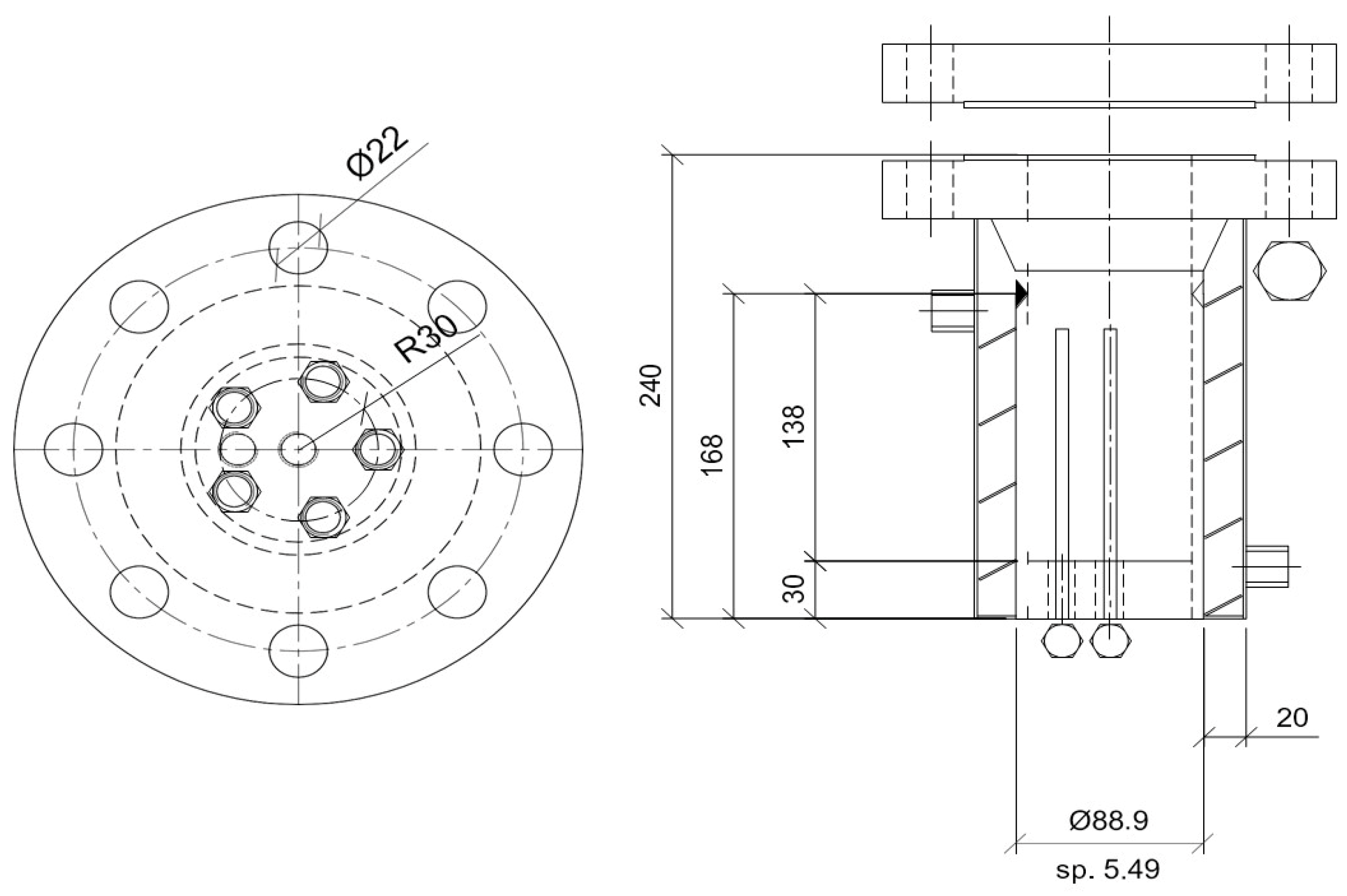
Technical details about the reactor can be found in Figure 2.
Further details can be easily found elsewhere in the literature [37].
Before flowing gas into the reactor, it was filled with demineralised water (744 cm3, by Merck, Rome, Italy) and porous sand (236 cm3). The quantities were selected to reach, after gas injection and in the case of ideal process evolution, a hydration number approximately equal to six [38]. In detail, the quantities were defined to operate in excess of water, thus ensuring the maximum capture of gas possible, which is mandatory to obtain precise dissociation curves. Conversely, the quantity of sand was selected in order to cover, with this porous medium, the whole volume occupied by water, thus avoiding the presence of regions below the gas–liquid interface where the production of hydrates would be unfeasible. The porous medium makes hydrate formation diffused along the whole reactor and not solely limited to the gas–liquid interface. It consists of pure silica spherical grains, having diameters between 0.09 and 0.15 mm. The mean porosity was evaluated with a porosimeter (model Thermo Scientific Pascal 140, Milan, Italy) and is equal to 34%. Ultra-high-purity (UHP, purity > 99.99%, provided by Nippon Gases, Milano, Italy) carbon dioxide and ethane were used for the experiments.

2.2. Experimental Procedure

Gas hydrates were produced with CO2/C2H6 mixtures; three concentrations were tested and, for each of these, four tests were carried out to ensure the reliability of results. In detail, these mixtures were as follows:
(1)
CO2/C2H6 (75/25) vol%: Tests 1–4;
(2)
CO2/C2H6 (50/50) vol%: Tests 5–8;
(3)
CO2/C2H6 (25/75) vol%: Tests 9–12.
The tests were performed following the same procedure adopted in previous studies for gas mixtures [39]: the guest mixture was injected into the reactor at relatively high temperatures to avoid the production of hydrates during gas flowing. The temperature was then slightly lowered (gradient approximately equal to 0.1–0.2 °C/h [40]) until approaching the freezing point of water. The pressure consequently decreased until establishing a configuration of equilibrium in correspondence with the lowest temperature fixed for the test. Finally, the temperature was increased again, with the same gradient previously mentioned, to cause hydrate dissociation. Pressure and temperature data were continuously monitored and registered during experiments.

3. Results

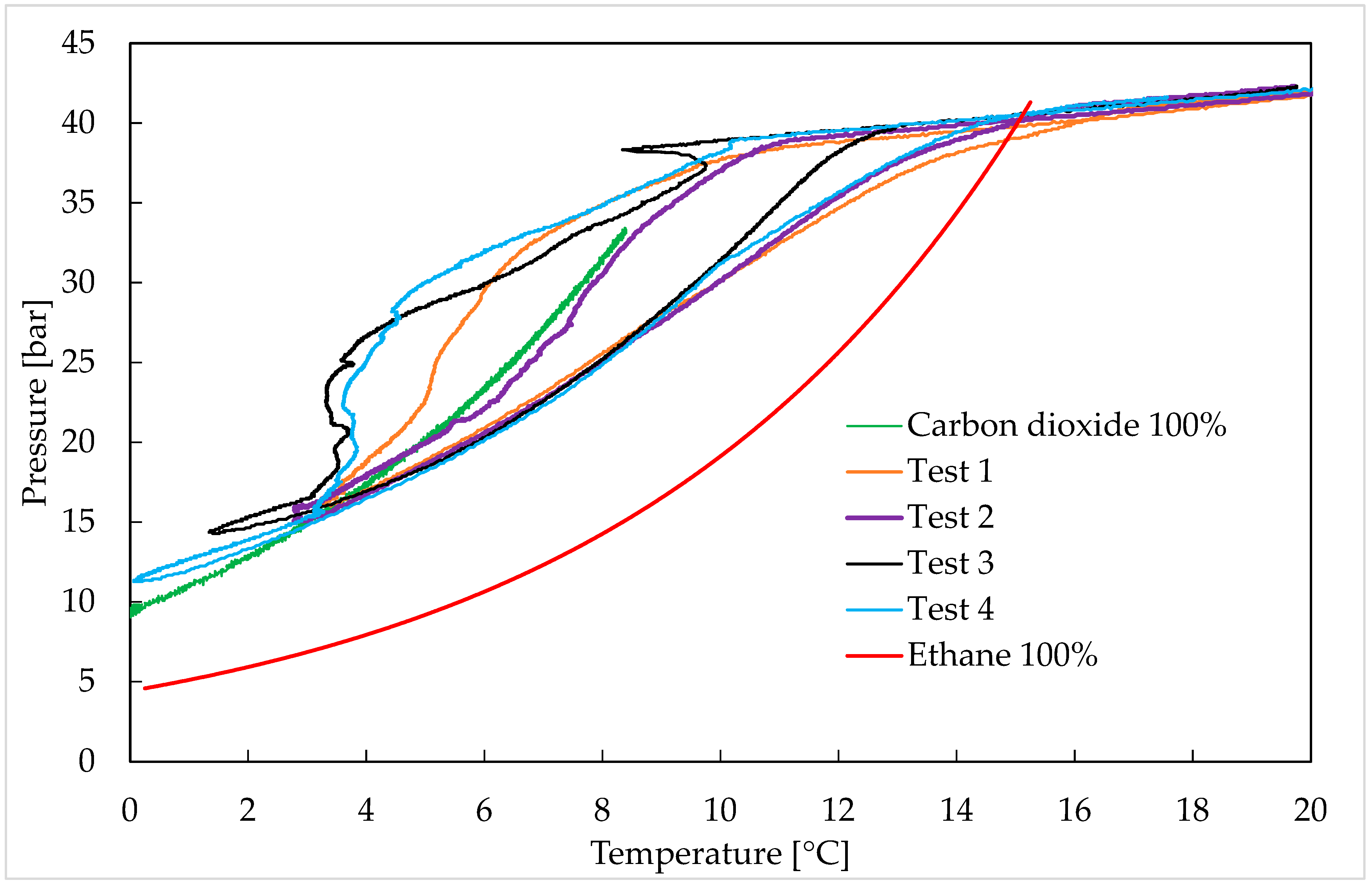
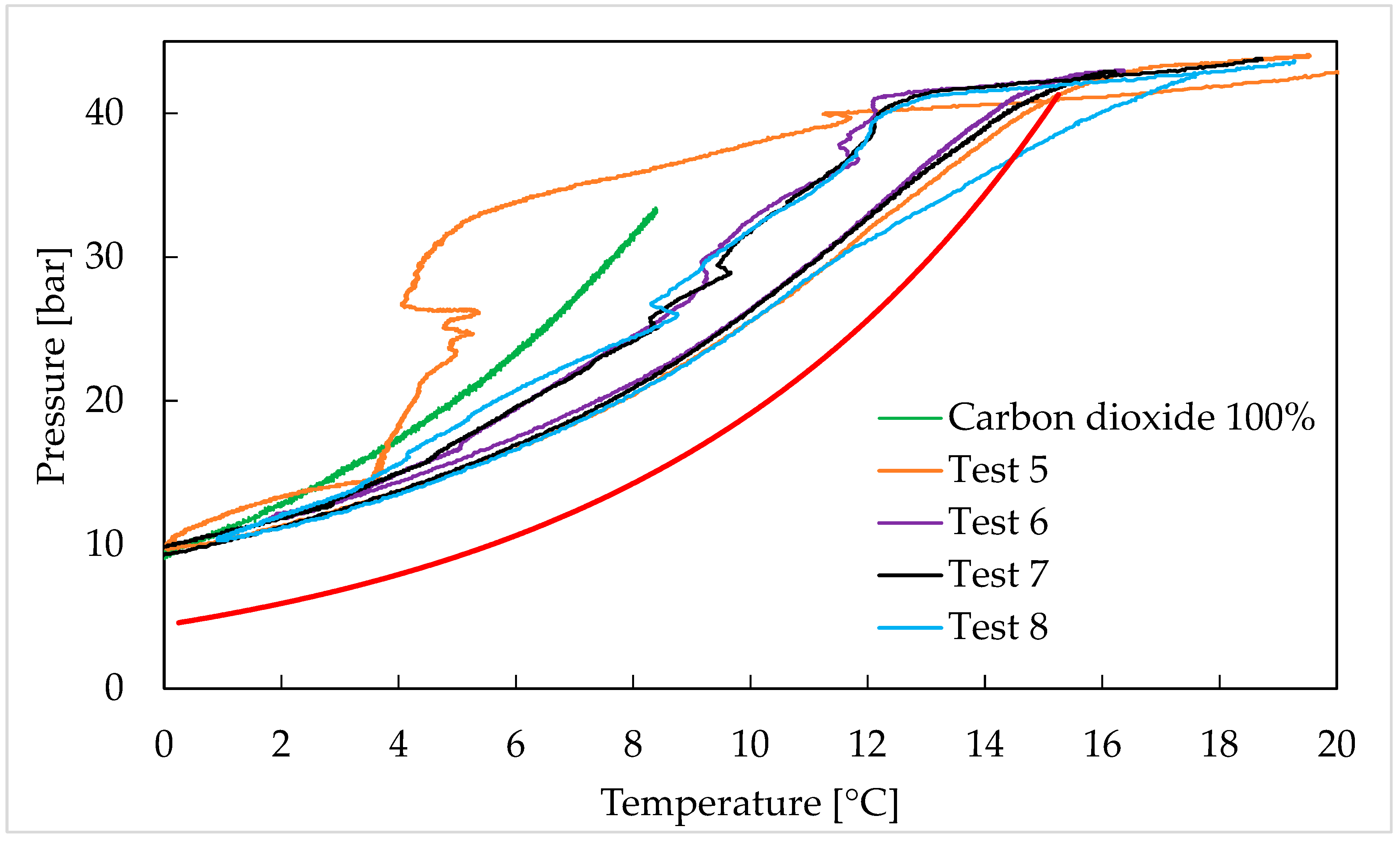
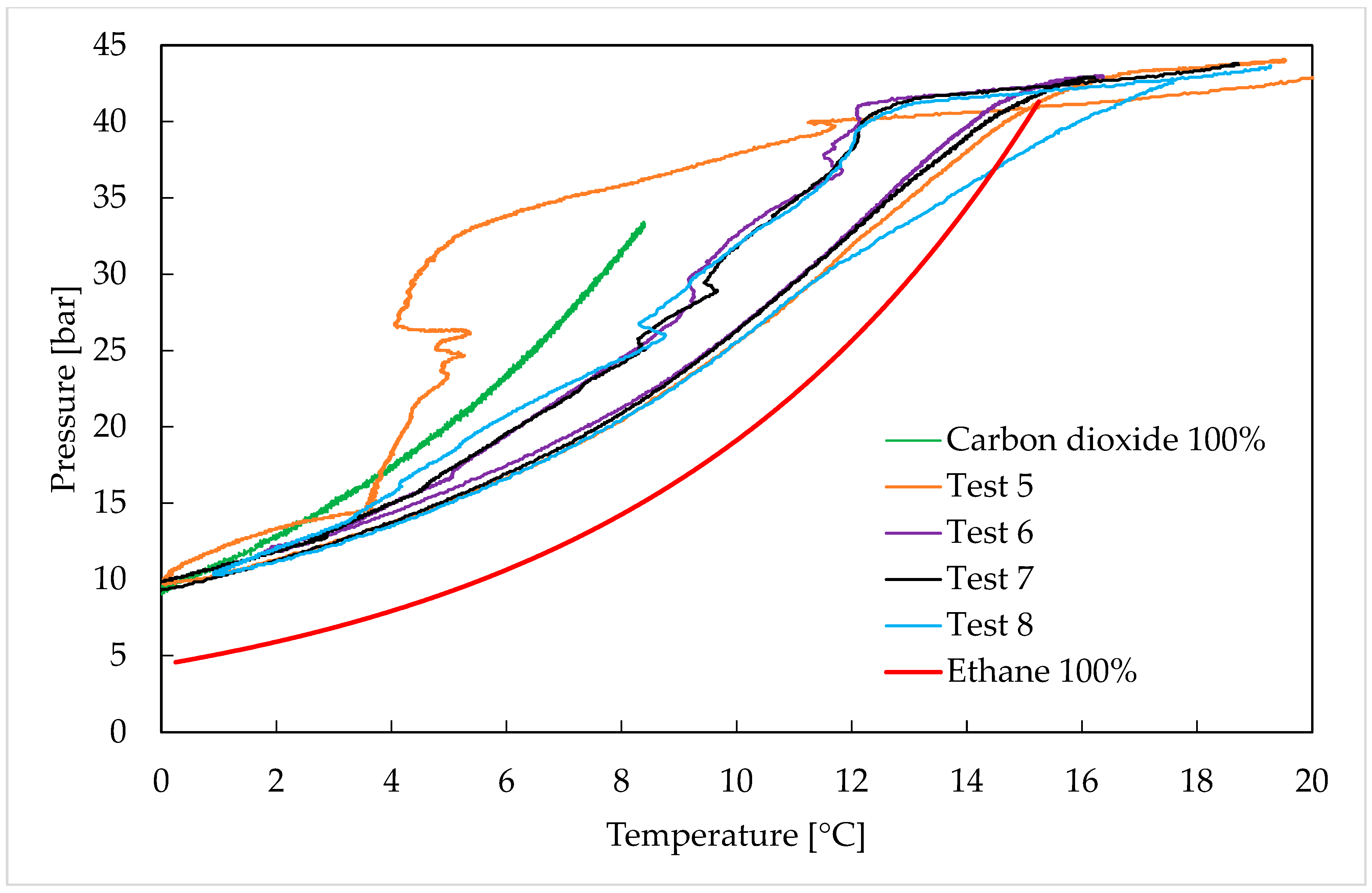
Gas hydrates were formed with binary gaseous mixtures containing carbon dioxide and ethane at different concentrations. In detail, Figure 3 describes the experiments carried out with CO2/C2H6 (75/25) vol%, and Table 1 shows the related dissociation values. Figure 4 and Table 2 are related to the CO2/C2H6 (50/50) vol% mixture, while Figure 5 and Table 3 are related to the CO2/C2H6 (25/75) vol% one. The dissociation values reported in each table were calculated as the mean of results obtained in the four experiments made with the same mixture. However, as deducible from the diagrams, the dissociation curves have a high similarity degree between each other.
The results were compared with the phase boundary equilibrium conditions of pure carbon dioxide and pure ethane hydrates, whose values were defined according to the current literature (references [41,42,43,44] for carbon dioxide hydrates and references [45,46,47,48,49] for ethane hydrates). In the diagrams, the phase boundary conditions were plotted in green for carbon dioxide hydrates and in red for ethane hydrates.
As previously stated in Section 2, the porous medium was used to ensure the widespread production of hydrates within the reactor, instead of limiting it in correspondence with the gas–liquid interface. The surface of sand grains is a good promoter for heterogeneous nucleation [49]. Moreover, the roughness of the grains allows them to capture gas molecules, keeping them below the gas–liquid interface, thus favouring a more intimate and diffused contact between water and guest molecules [50]. Both the production and melting of hydrates consist of limited mass transfer and heat transfer processes. The thermal conductivity of methane hydrates is equal to 0.5 W/mK, lower than liquid water [51]. This value becomes still lower in the presence of other short-chain hydrocarbons: the thermal conductivity of propane hydrates is equal to 0.39 W/mK [52]. During dissociation, this could result in the excessively delayed and not temperature-coherent melting of clathrate structures. Sand and rocks allow an increase in the overall thermal conductivity, thus balancing its lowering related to the massive presence of hydrates [53]. The role of sediments during hydrate formation and dissociation has been widely investigated in the literature [53]. Recent studies highlighted that, at a given pressure, nano-fossil-rich sediments shift the stability of hydrates containing hydrocarbons to temperatures lower than 0.5 °C [54,55]. Conversely, silica sand was proven to enhance the stability of hydrates, making their stability also feasible at pressures lower (considering the same temperature) than those describing the corresponding ideal phase boundary equilibrium [56,57].
The results shown in this section confirmed the stochastic behaviour of the formation process: the growth of hydrate crystals defined thermodynamic trends widely different among each other. It should be noted that the experimental procedure was equal in all the tests: starting from the initial pressure–temperature conditions, the internal temperature was lowered with velocity equal to 0.1–0.12 °C/h. However, in some tests, the local conditions moved within the region of stability of pure carbon dioxide hydrates before observing the massive production of hydrates. Despite these differences, the formation process showed recognisable and marked elements in almost all the tests, independently from the group they belong to.
Firstly, the massive production of hydrates did not appear as soon as the thermodynamic conditions became feasible for the process, denoting the existence of a certain induction period, during which the dependency between pressure and temperature remained the same as that observed before the system reached the region of formation and stability for ethane hydrates (the left side of the red curve describing the phase equilibrium conditions for ethane hydrates).
In most of the experiments, the effective beginning of massive hydrate formation caused a peak in temperature due to the exothermicity of the process. That peak was observed in each group of experiments; therefore, it occurred independently from the initial concentration selected for the binary mixture. Those peaks denoted a temporary reversion of temperature within the reactor, even though the cooling room constantly remained switched on, proving the internal production of heat exclusively linked to the exothermicity of hydrate formation. Immediately after the peak, hydrates started forming massively, and the pressure decreased until reaching its configuration of equilibrium. The internal production of heat continued during the whole formation; however, since the process occurred gradually, the heat removal balanced the internal production well.
In all three groups of experiments, the formation process ended only after the system reached the phase equilibrium conditions of pure carbon dioxide hydrates.
While the dissociation curves of tests belonging to the same group showed high similarity among each other (the corresponding curves were overlapped in the diagrams, and the differences between the data measured often remained below the accuracy of the instruments), the formation process often showed marked differences. This trend brought together all the groups of tests and perfectly agreed with the theories describing the mechanism behind hydrate formation and dissociation. The production of hydrates is a highly stochastic process, especially due to the initial nucleation step, during which, according to the Labile Cluster Theory, the growth of initial primordial nuclei is mainly a function of the collision between clusters diffused in the bulk phase. In the absence of collisions, these clusters would inevitably go through dissociation, since they cannot autonomously overcome the energy barrier required for their growth. The process feasibility changes after the so-called “critical size” is reached; then, the hydrate nuclei are capable of growth without the need for collisions with surrounding entities. This latter step of the process is defined as the “catastrophic growth phase”. Conversely, the dissociation of hydrates is mainly governed by the heat and mass transfer properties of the system and is therefore more deterministic. For that reason, the phase boundary equilibrium conditions of hydrate systems are always defined by using dissociation data.
Following the methodology discussed in Section 2, once the formation ended, the temperature was gradually increased to make the local condition unsuitable for the stability of hydrates. Their dissociation started immediately, proving that the formation process reached the phase boundary equilibrium conditions for the system. Only a few exceptions were observed in part of the experiments carried out with the CO2/C2H6 (25/75) vol%, but it can be associated with the premature interruption of the formation process during the tests, as visible in Figure 5. During hydrate melting, the internal pressure continuously and gradually increased until the system reached the same configuration shown before hydrate formation.
The pressure–temperature values measured during hydrate dissociation resulted intermediate between the phase equilibrium conditions of pure CO2 and pure C2H6 hydrates, thus confirming the production of structures containing both the species (if the two species formed hydrates separately, the final P-T conditions should have matched the phase equilibrium conditions of pure CO2 hydrates). Both the species spontaneously form sI hydrates, a cubic structure containing the two different polyhedral cages discussed in the Introduction. While ethane can exclusively fit the larger cavities, carbon dioxide molecules can also enter in the small pentagonal dodecahedrons, even though, being the cage-filling ratio equal to one, the process inevitably requires geometrical distortion [48]. However, the capture of ethane molecules in the larger cavities ensures the highest stability possible for these cages, with the filling ratio equal to 0.939. The improved stability facilitates the capture of carbon dioxide in the smaller cavities [58].
With the increase in the ethane concentration in the initial gaseous mixture, the experimental curves gradually approached the phase equilibrium curve of pure ethane hydrates. In tests carried out with the mixture containing 75 vol% ethane (see Tests 9–12), the experimental results equalised the dissociation values of pure ethane hydrates, proving that the melting condition exclusively depended on this latter species.
The experimental evidence of this study is in agreement with previous studies carried out with mixtures containing the same species (ethane and carbon dioxide) [59]. Robustillo and colleagues [59] observed that ethane added as a stabilizer for hydrates increased the cage occupancy within the crystalline lattice and allowed a reduction in the pressures required for hydrate formation.
The latter result does not main that carbon dioxide did not participate to the production of hydrates; both the species were captured in water cages, but the stability of the crystalline lattice exclusively depended on ethane hydrates. That is what occurs when molecules such as nitrogen or, mostly, hydrogen, are present in mixtures used for the production of hydrates. By themselves, these species would require extremely high pressure to be captured. However, if used in a mixture, their capture is possible since the aiding molecules ensure the required stability, thus also preserving the cavities containing these smaller-sized molecules, which could not provide stability to their corresponding water cages [60].
This result confirmed again the thesis previously discussed. The ratio between large and small cages in sI is 3:1. The usage of a binary mixture having the same ratio between ethane and carbon dioxide molecules ensured the maximum stability possible for the system. As a consequence of this, the hydrates dissociated only after the system reached the phase equilibrium conditions of pure ethane hydrates. These results allow us to better understand how small-chain hydrocarbons such as, in this case, ethane, affect the capture of carbon dioxide into hydrates and change the melting condition of hydrates.

4. Conclusions

Gas hydrates were formed and dissociated with binary CO2/C2H6 mixtures at three different concentrations, (25/75), (50/50) and (75/25) in volume. Experiments were carried out with a small-scale apparatus working in unstirred conditions. The diffused production of hydrates within the reactor was ensured by using silica sand, which created a porous bed capable of creating gas–liquid interfaces throughout the whole internal volume.
Each mixture was tested during multiple experiments, and the mean values were tabulated and provided in the text. The forming and melting processes were compared with the phase boundary equilibrium conditions of pure carbon dioxide and pure ethane hydrates, respectively.
Separately, both the species form sI hydrates, where the large cavities are preferentially occupied. However, CO2 molecules are also capable of fitting the small cavities of that structure, while C2H6 molecules, due to their size, can exclusively fit the larger cages. Therefore, mixed hydrates occur if the small cavities are occupied by carbon dioxide molecules, while ethane molecules are captured within the larger cavities.
The higher the concentration of ethane, the lower the pressures describing hydrate melting. In tests carried out with the CO2/C2H6 (25/75) vol% mixture, the system reached the mildest melting conditions possible, corresponding to the phase equilibrium configuration for pure ethane hydrates. In the thermodynamic region included between 0.1 °C and 13 °C, the pressures required for hydrate melting approached those describing the phase equilibrium conditions of pure ethane hydrates, representing the lowest melting condition possible for the system studied in this study. That result proved that once hydrates were formed, the content in carbon dioxide did not affect the melting conditions. Therefore, the stability of structures exclusively depended on the structures including ethane.
As further confirmation, this result was obtained when the mixture composition reflected the ratio between large and small cavities in sI (3:1).

Author Contributions

Conceptualisation, A.M.G. and F.R.; methodology, A.M.G.; validation, F.R. and G.G.; investigation, A.M.G.; resources, F.R.; data curation, A.M.G.; writing—original draft preparation, A.M.G. and G.G.; writing—review and editing, F.R. and G.G.; supervision, G.G.; project administration, F.R.; funding acquisition, F.R. All authors have read and agreed to the published version of the manuscript.

Funding

The authors gratefully acknowledge financial support derived by the PNRR project entitled: “High Efficiency Hydrogen Storage (HEHS)”, ID: RSH2B_000052 (to Giovanni Gigliotti and Federico Rossi).

Data Availability Statement

Data sources are available within a specific repository. Repository name: Mendeley Data; Name: CO2-C2H6 hydrates; URL: https://data.mendeley.com/datasets/tk73n96ryz/1 accessed on 14 August 2025.

Acknowledgments

The authors acknowledge the technical and material contribution of AiZoOn Technology Consulting and Nippon Gases Industrial Srl.

Conflicts of Interest

The authors declare no conflicts of interest.

References

  1. Koh, C.A.; Sloan, E.D. Natural gas hydrates: Recent advances and challenges in energy and environmental applications. AIChE J. 2007, 53, 1636–1643. [Google Scholar] [CrossRef]
  2. Gambelli, A.M.; Rossi, F. Thermodynamic and kinetic characterization of methane hydrate nucleation, growth and dissociation processes, according to the Labile Cluster Theory. Chem. Eng. J. 2021, 425, 130706. [Google Scholar] [CrossRef]
  3. Li, X.S.; Xu, C.G.; Zhang, Y.; Ruan, X.K.; Li, G.; Wang, Y. Investigation into gas production from natural gas hydrate: A review. Appl. Energy 2016, 172, 286–322. [Google Scholar] [CrossRef]
  4. Goel, N. In Situ methane hydrate dissociation with carbon dioxide sequestration: Current knowledge and issues. J. Petrol. Sci. Eng. 2009, 51, 169–184. [Google Scholar] [CrossRef]
  5. Nair, V.C.; Prasad, S.K.; Kumar, R.; Sangway, J.S. Energy recovery from simulated clayey gas hydrate reservoir using depressurization by constant rate gas release, thermal stimulation and their combination. Appl. Energy 2018, 225, 755–768. [Google Scholar] [CrossRef]
  6. Xuan, K.; Yi, W.; Li, X.S.; Zhang, Y.; Chen, Z.Y. Influence of heat conduction and heat convection on hydrate dissociation by depressurization in a pilot-scale hydrate simulator. Appl. Energy 2019, 251, 113405. [Google Scholar] [CrossRef]
  7. Wang, Y.; Feng, J.C.; Li, X.S.; Zhang, Y. Experimental investigation of optimization of well spacing for gas recovery from methane hydrate reservoir in sandy sediment by heat stimulation. Appl. Energy 2017, 207, 562–572. [Google Scholar] [CrossRef]
  8. Go, W.; Yun, S.; Lee, D.; Seo, Y. Experimental and computational investigation of hydrophilic monomeric substances as novel CO2 hydrate inhibitors and potential synergists. Energy 2022, 244, 123136. [Google Scholar] [CrossRef]
  9. Lu, Y.; Yuan, C.; Wang, H.; Yang, L.; Zhang, L.; Zhao, J.; Song, Y. Atomistic insight into the performance of thermodynamic inhibitors in the nucleation of methane hydrate. Chem. Eng. J. 2022, 431, 133479. [Google Scholar] [CrossRef]
  10. Gambelli, A.M.; Rossi, F. Natural gas hydrates: Comparison between two different applications of thermal stimulation for performing CO2 replacement. Energy 2019, 172, 423–434. [Google Scholar] [CrossRef]
  11. Sloan, E.D.; Koh, C.A. Clathrate Hydrates of Natural Gases, 3rd ed.; CRC Press: Boca Raton, FL, USA; New York, NY, USA, 2008. [Google Scholar]
  12. Jeffrey, J.A. Hydrate inclusion compounds. J. Incl. Phenom. 1984, 1, 211–222. [Google Scholar] [CrossRef]
  13. Pauling, L.; Marsh, R.E. The structure for inert gas hydrates. Proc. Natl. Acad. Sci. USA 1952, 38, 1425–1426. [Google Scholar] [CrossRef]
  14. Claussen, W.F. A second water structure for inert gas hydrates. J. Chem. Phys. 1951, 19, 1425–1426. [Google Scholar] [CrossRef]
  15. Ripmeester, J.A.; Tse, J.S.; Ratcliffe, C.I.; Powell, B.M. A new clathrate hydrate structure. Nature 1987, 325, 135–136. [Google Scholar] [CrossRef]
  16. Ailin, J. Progress and prospects of natural gas development technologies in China. Nat. Gas Ind. B 2018, 5, 547–557. [Google Scholar] [CrossRef]
  17. Demirbas, A. Natural gas. In Methane Gas Hydrate; Chapter 2; Springer: London, UK, 2010; pp. 57–76. [Google Scholar]
  18. Gambelli, A.M. Variations in terms of CO2 capture and CH4 recovery during replacement processes in gas hydrate reservoirs, associated to the “memory effect”. J. Clean. Prod. 2022, 360, 132154. [Google Scholar] [CrossRef]
  19. Zhang, Y.; Zhai, X.; Zhang, F.; Zhang, Z.; Hooman, K.; Zhang, H.; Wang, X. A biomimetic red blood cell inspired encapsulation design for advanced hydrate-based carbon capture. Energy 2023, 271, 126985. [Google Scholar] [CrossRef]
  20. Giovannetti, R.; Gambelli, A.M.; Castellani, B.; Rossi, A.; Minicucci, M.; Zannotti, M.; Li, Y.; Rossi, F. May sediments affect the inhibiting properties of NaCl on CH4 and CO2 hydrates formation? An experimental report. J. Mol. Liq. 2022, 359, 119300. [Google Scholar] [CrossRef]
  21. Dhamu, V.; Qureshi, M.F.; Barckholtz, T.A.; Mhadeshwar, A.B.; Linga, P. Evaluating liquid CO2 hydrate formation kinetics, morphology, and stability in oceanic sediments on a lab scale using top injection. Chem. Eng. J. 2023, 478, 147200. [Google Scholar] [CrossRef]
  22. Lee, Y.J.; Kawamura, T.; Yamamoto, Y.; Yoon, J.H. Phase equilibrium studies of tetrahydrofuran (THF) + CH4, THF + CO2, CH4 + CO2, and THF + CO2 + CH4 hydrates. J. Chem. Eng. Data 2012, 57, 3543–3548. [Google Scholar] [CrossRef]
  23. Yi, L.; Liang, D.; Zhou, X.; Li, D. Molecular dynamics simulations for the growth of CH4-CO2 mixed hydrate. J. Energy Chem. 2014, 23, 747–754. [Google Scholar] [CrossRef]
  24. Dornas, P.; Alavi, S.; Woo, T.K. Free energies of carbon dioxide sequestration and methane recovery in clathrate hydrates. J. Chem. Phys. 2007, 127, 124510. [Google Scholar] [CrossRef]
  25. Kang, S.P.; Lee, H. Recovery of CO2 from flue gas using gas hydrate: Thermodynamic verification through phase equilibrium measurements. Environ. Sci. Technol. 2000, 34, 4397–4400. [Google Scholar] [CrossRef]
  26. Ding, Y.L.; Xu, C.G.; Yu, Y.S.; Li, X.S. Methane recovery from natural gas hydrate with simulated IGCC syngas. Energy 2017, 120, 192–198. [Google Scholar] [CrossRef]
  27. .Gambelli, A.M.; Presciutti, A.; Rossi, F. Kinetic considerations and formation rate for carbon dioxide hydrate, formed in presence of a natural silica-based porous medium: How initial thermodynamic conditions may modify the process kinetic. Thermochim. Acta 2021, 705, 179039. [Google Scholar] [CrossRef]
  28. Sun, S.; Zhang, Y.; Kong, Y.; Liu, C.; Liu, Y. Preliminary study on measurement technology for hydrate phase equilibrium. Fluid Phase Equilibr. 2015, 403, 60–69. [Google Scholar]
  29. Gambelli, A.M.; Rossi, F.; Gigliotti, G. Methane replacement by using CO2/C3H8 mixtures for carbon storage and enhanced methane recovery in gas hydrates. Gas Sci. Eng. 2023, 115, 205028. [Google Scholar] [CrossRef]
  30. Ricaurte, M.; Torré, J.P.; Diaz, J.; Dicharry, C. In Situ injection of THF to trigger gas hydrate crystallization: Application to the evaluation of a kinetic hydrate promoter. Chem. Eng. Res. Des. 2014, 92, 1674–1680. [Google Scholar] [CrossRef]
  31. Torré, J.P.; Ricaurte, M.; Dicharry, C.; Broseta, D. CO2 enclathration in the presence of water-soluble hydrate promoters: Hydrate phase equilibria and kinetic studies in quiescent conditions. Chem. Eng. Sci. 2012, 82, 1–13. [Google Scholar] [CrossRef]
  32. Babu, P.; Yang, T.; Veluswamy, H.P.; Kumar, R.; Linga, P. Hydrate phase equilibrium of ternary gas mixture containing carbon dioxide, hydrogen and propane. J. Chem. Thermodyn. 2013, 61, 58–63. [Google Scholar] [CrossRef]
  33. Lang, F.; Servio, P. Solubility measurements for the CH4 + C2H6 + H2O system under hydrate-liquid-vapour equilibrium. J. Nat. Gas Sci. Eng. 2015, 26, 130–134. [Google Scholar] [CrossRef]
  34. Zhong, J.; Sun, Y.; Sun, C.; Chen, G. Structural transitions range of methane + ethane gas hydrates during the decomposition process below the ice point. Energy Proc. 2019, 158, 5201–5206. [Google Scholar] [CrossRef]
  35. Bhawangirkar, D.R.; Adhikari, J.; Sangway, J.S. Thermodynamic modelling of phase equilibria of clathrate hydrates formed from CH4, CO2, C2H6 and C3H8, with different equations of state. J. Chem. Thermodyn. 2018, 117, 180–192. [Google Scholar] [CrossRef]
  36. Rovetto, L.J.; Bowler, K.E.; Stadterman, L.L.; Dec, S.F.; Koh, C.A.; Sloan, E.D. Dissociation studies of CH4-C2H6 and CH4-CO2 binary gas hydrates. Fluid Phase Equilibr. 2007, 261, 407–413. [Google Scholar] [CrossRef]
  37. Gambelli, A.M.; Rossi, F. Experimental characterization of the difference in induction period between CH4 and CO2 hydrates: Motivation and possible consequences on the replacement process. J. Nat. Gas Sci. Eng. 2022, 108, 104848. [Google Scholar] [CrossRef]
  38. Fitzgerald, G.C.; Castaldi, M.J.; Zhou, Y. Large scale reactor details and results for the formation and decomposition of methane hydrates via thermal stimulation dissociation. J. Pet. Sci. Eng. 2012, 94–95, 19–27. [Google Scholar] [CrossRef]
  39. Yu, S.H.; Zhou, S.D.; Li, X.S.; Wang, S.L. Effect of graphite nanoparticles on CO2 hydrate phase equilibrium. Fluid Phase Equilibr. 2016, 414, 23–28. [Google Scholar] [CrossRef]
  40. Cao, X.; Yang, K.; Xia, W.; Tang, G.; Bian, J. Dissociation experiment and dissociation rate model of CO2 hydrate. Nat. Gas Ind. B 2021, 8, 607–614. [Google Scholar] [CrossRef]
  41. Jarrahian, A.; Nakhaee, A. Hydrate-liquid-vapor equilibrium condition for N2 + CO2 + H2O system: Measurement and modelling. Fuel 2019, 237, 769–774. [Google Scholar] [CrossRef]
  42. Kyung, D.; Lee, K.; Kim, H.; Lee, W. Effect of marine environmental factors on the phase equilibrium of CO2 hydrate. Int. J. Greenh. Gas Control 2014, 20, 285–292. [Google Scholar] [CrossRef]
  43. Seo, Y.T.; Lee, H. Multiple-phase hydrate equilibria of the ternary carbon dioxide, methane, and water mixtures. J. Phys. Chem. B 2001, 105, 10084–10090. [Google Scholar] [CrossRef]
  44. Hendriks, E.M.; Edmond, B.; Moorwood, R.A.S.; Szcepanski, R. Hydrate structure stability in simple and mixed hydrates. Fluid Phase Equilibr. 1996, 117, 193–200. [Google Scholar] [CrossRef]
  45. Subramanian, S.; Kini, R.A.; Dec, S.F.; Sloan, E.D. Evidence of structure II hydrate formation from methane + ethane mixtures. Chem. Eng. Sci. 2000, 55, 1981–1999. [Google Scholar] [CrossRef]
  46. Sun, Y.H.; Zhang, G.B.; Carroll, J.J.; Li, S.L.; Jiang, S.H.; Guo, W. Experimental investigation into gas recovery from CH4-C2H6 C3H8 hydrates by CO2 replacement. Appl. Energy 2018, 229, 625–636. [Google Scholar] [CrossRef]
  47. Sundramoorthy, J.D.; Hammonds, P.; Lal, B.; Philips, G. Gas hydrate equilibrium measurement and observation of gas hydrate dissociation with/without a KHI. Procedia Eng. 2016, 148, 870–877. [Google Scholar] [CrossRef]
  48. Gambelli, A.M.; Rossi, F.; Gigliotti, G. Hydrates production with binary CO2/C3H8 gaseous mixtures (90/10, 85/15, 80/20 vol%) in batch and unstirred conditions: The role of propane on the process thermodynamics. Chem. Eng. Sci. 2024, 298, 120441. [Google Scholar] [CrossRef]
  49. Giovannetti, R.; Gambelli, A.M.; Rossi, A.; Castellani, B.; Minicucci, M.; Zannotti, M.; Nicolini, A.; Rossi, F. Thermodynamic assessment and microscale Raman spectroscopy of binary CO2/CH4 hydrates produced during replacement applications in natural reservoirs. J. Mol. Liq. 2022, 368, 120739. [Google Scholar] [CrossRef]
  50. Gambelli, A.M. Methane replacement into hydrate reservoirs with carbon dioxide: Main limiting factors and influence of the gaseous phase composition, over hydrates, on the process. Chem. Eng. J. 2023, 478, 147247. [Google Scholar] [CrossRef]
  51. Waite, W.F.; Gilbert, L.Y.; Winters, W.J.; Mason, D.H. Thermal property measurements in tetrahydrofuran (THF) hydrate between −25 and +4 °C and their application to methane hydrate. In Proceedings of the 5th International Conference on Gas Hydrates, Trondheim, Norway, 12–16 June 2005. [Google Scholar]
  52. Stoll, R.D.; Bryan, G.M. Physical properties of sediments containing gas hydrates. J. Geophys. Res. 1979, 84, 1629–1634. [Google Scholar] [CrossRef]
  53. Max, M.D. Natural Gas Hydrates in Oceanic and Permafrost Environments; Kluwer Academic Publisher: Amsterdam, The Netherlands, 2000. [Google Scholar]
  54. Lu, H.; Matsumoto, R. Preliminary experimental results of the stable P-T conditions of methane hydrate in a nannofossil-rich claystone column. Geochem. J. 2002, 36, 21–30. [Google Scholar] [CrossRef]
  55. Di Profio, P.; Arca, S.; Savelli, G. Novel nanostructured media for gas storage and transport: Clathrate hydrates of methane and hydrogen. J. Fuel Cell Sci. Technol. 2007, 4, 49–55. [Google Scholar] [CrossRef]
  56. Gambelli, A.M.; Di Schino, A.; Rossi, f. Experimental characterization of CH4 and CO2 hydrates formation in presence of porous quartz and Cu gas-atomized particles: Thermodynamic analyses and evidences about the feasibility of CH4/CO2 reverse replacement. Chem. Eng. Res. Des. 2022, 186, 511–524. [Google Scholar] [CrossRef]
  57. Hachikubo, A.; Takeya, S.; Chuvilin, E.; Istomin, V. Preservation phenomena of methane hydrate in pore spaces. PCCP 2011, 13, 17449–17452. [Google Scholar] [CrossRef] [PubMed]
  58. Gambelli, A.M.; Rossi, F. Re-definition of the region suitable for CO2/CH4 replacement into hydrates as a function of the thermodynamic difference between CO2 hydrate formation and dissociation. Proc. Saf. Environ. Prot. 2023, 169, 132–141. [Google Scholar] [CrossRef]
  59. Robustillo, M.D.; de Menezes, D.E.S.; de Alcântara Pessôa Filho, P. Phase equilibrium of double-guest clathrates of methane and CO2, ethane, or propane as measured by high-pressure microcalorimetry. J. Mol. Liq. 2023, 387, 122609. [Google Scholar] [CrossRef]
  60. Gambelli, A.M.; Presciutti, A.; Rossi, F. Review on the characteristics and advantages related to the use of flue-gas as CO2/N2 mixture for gas hydrate production. Fluid Phase Equilibr. 2021, 541, 113077. [Google Scholar] [CrossRef]
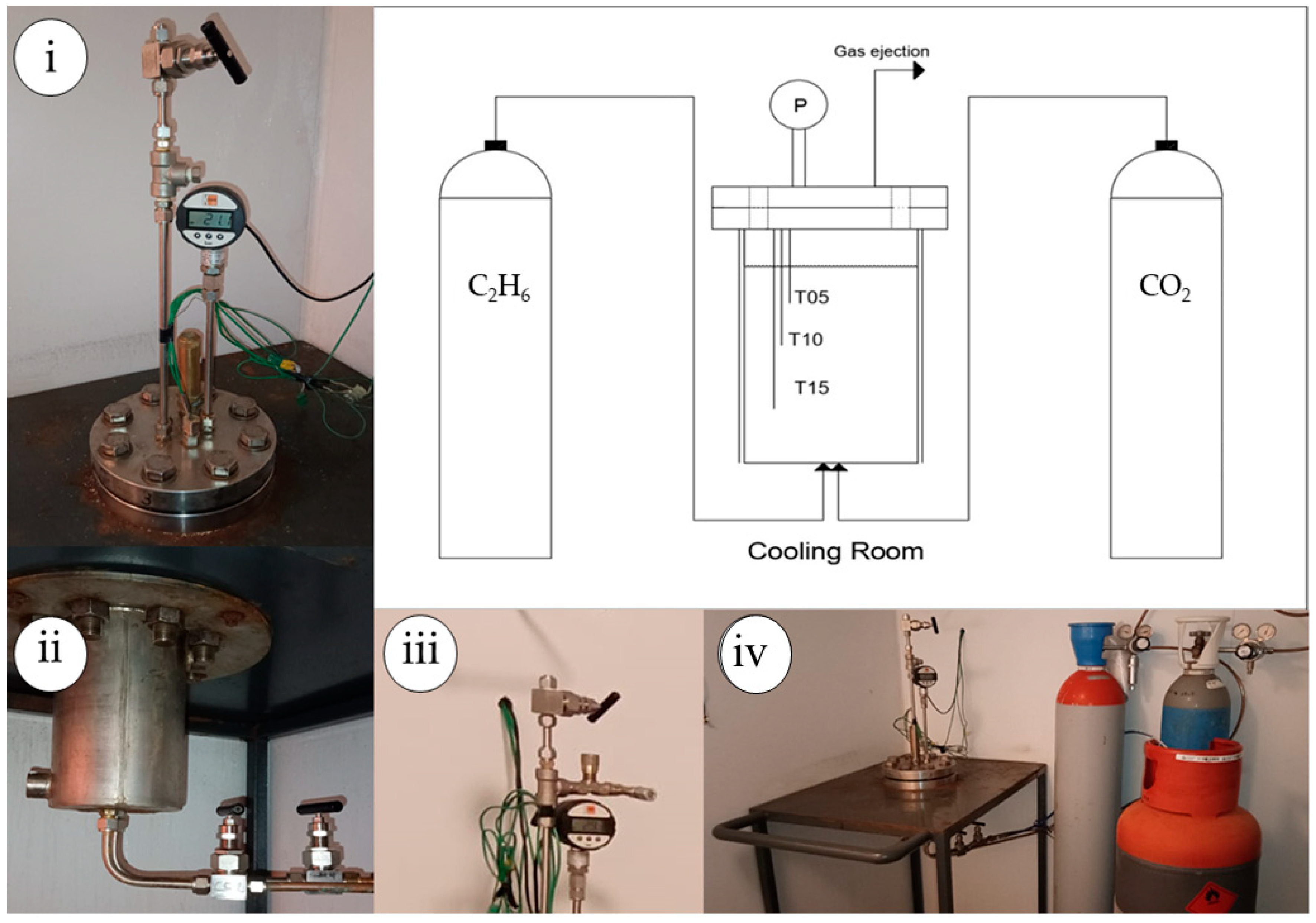
Figure 1. Scheme of the reactor describing the positioning of sensors used during tests and showing the connections with gas cylinders. Pictures: (i) flange hosting the gas ejection channel, the various sensors and a safety valve; (ii) channels connecting gas cylinders and the reactor; (iii) zoomed-in picture of the gas ejection channel and (iv) whole apparatus positioned within the cooling room.
Carbon 11 00063 g001
Figure 2. Geometrical details of the device used for gas hydrates formation. Measures are reported in cm.
Carbon 11 00063 g002
Figure 3. P-T evolution of hydrate formation and dissociation with binary CO2/C2H6 (75/25) vol% gaseous mixtures. Comparison with the phase equilibrium conditions of pure CO2 (in green) and pure C2H6 (in red) hydrates.
Carbon 11 00063 g003
Figure 4. P-T evolution of hydrate formation and dissociation with binary CO2/C2H6 (50/50) vol% gaseous mixtures. Comparison with the phase equilibrium conditions of pure CO2 (in green) and pure C2H6 (in red) hydrates.
Carbon 11 00063 g004
Figure 5. P-T evolution of hydrate formation and dissociation with binary CO2/C2H6 (25/75) vol% gaseous mixtures. Comparison with the phase equilibrium conditions of pure CO2 (in green) and pure C2H6 (in red) hydrates.
Carbon 11 00063 g005
Table 1. Pressure–temperature data measured during the dissociation of hydrates produced with binary CO2/C2H6 (75/25) vol% gaseous mixtures. Data were considered as average of values measured during Tests 1–4. Uncertainty of measures: ±0.01 °C and ±0.05 bar.
T [°C]P [bar]T [°C]P [bar]T [°C]P [bar]T [°C]P [bar]
0.111.263.415.466.721.69.929.85
0.211.333.515.576.821.851030.13
0.311.353.615.746.922.0110.130.38
0.411.423.715.88722.3310.230.64
0.511.433.816.167.122.5210.330.86
0.611.563.916.277.222.8210.430.97
0.711.67416.497.323.0110.531.16
0.811.754.116.587.423.1710.631.46
0.911.834.216.847.523.5110.731.74
111.944.316.997.623.7910.831.99
1.112.074.417.087.72410.932.2
1.212.244.517.357.824.261132.5
1.312.324.617.357.924.611.132.69
1.412.434.717.68824.7911.232.86
1.512.654.817.768.125.1711.333.1
1.612.734.918.098.225.4111.433.34
1.712.92518.188.325.6911.533.58
1.813.015.118.378.425.9811.633.75
1.913.265.218.458.526.3611.734.07
213.345.318.688.626.6711.834.26
2.113.425.418.958.726.9411.934.42
2.213.535.519.088.827.271234.66
2.313.755.619.278.927.6312.134.82
2.413.955.719.46927.8512.235.07
2.514.035.819.689.128.1812.335.32
2.614.175.919.959.228.4512.435.51
2.714.34620.039.328.5312.535.74
2.814.456.120.289.428.8712.635.93
2.914.626.220.449.528.9512.736.16
314.776.320.769.629.2712.836.3
3.114.966.421.019.729.4512.936.53
3.215.166.521.179.829.631336.75
3.315.36.621.44
Table 2. Pressure–temperature data measured during dissociation of hydrates produced with binary CO2/C2H6 (50/50) vol% gaseous mixtures. Data were considered as average of values measured during Tests 5–8. Uncertainty of measures: ±0.01 °C and ±0.05 bar.
T [°C]P [bar]T [°C]P [bar]T [°C]P [bar]T [°C]P [bar]T [°C]P [bar]
0.19.742.712.065.315.567.920.2710.627.27
0.29.792.812.235.415.65820.4310.727.43
0.39.872.912.315.515.878.120.7510.827.75
0.49.91312.565.615.988.220.9210.928.17
0.59.943.112.645.716.158.321.161128.45
0.610.063.212.735.816.48.421.4311.128.86
0.710.063.312.845.916.578.521.7311.229.03
0.810.123.413616.658.621.9211.329.45
0.910.213.513.146.116.98.722.2511.429.77
110.293.613.256.216.998.822.4111.530.05
1.110.433.713.416.317.188.922.5911.630.46
1.210.543.813.536.417.34922.8911.730.88
1.310.623.913.666.517.489.223.511.831.16
1.410.71413.786.617.769.323.6911.931.46
1.510.824.113.946.717.879.423.911231.88
1.610.964.214.036.818.099.524.112.132.27
1.711.044.314.166.918.289.624.5112.232.5
1.811.134.414.25718.379.724.6712.332.8
1.911.244.514.367.118.679.82512.433.18
211.324.614.537.218.869.925.2712.533.34
2.111.44.714.627.318.941025.5312.633.72
2.211.544.814.877.419.2610.125.8512.734.07
2.311.744.914.967.519.3410.226.0812.834.34
2.411.74515.157.619.6710.326.3612.934.66
2.511.825.115.297.719.8610.426.661335.07
2.611.925.215.397.820.0310.526.85
Table 3. Pressure–temperature data measured during dissociation of hydrates produced with binary CO2/C2H6 (25/75) vol% gaseous mixtures. Data were considered as average of values measured during Tests 9–12. Uncertainty of measures: ±0.01 °C and ±0.05 bar.
T [°C]P [bar]T [°C]P [bar]
717.361021.33
7.117.3810.121.52
7.217.4210.221.74
7.317.4710.322.12
7.417.4810.422.42
7.517.510.522.52
7.617.5410.622.9
7.717.5710.723.09
7.817.6110.823.51
7.917.6410.923.7
817.661124
8.117.6911.124.2
8.217.7711.224.6
8.317.8811.324.79
8.418.1011.425.17
8.518.3011.525.5
8.618.3811.625.77
8.718.6011.726.09
8.818.7911.826.36
8.918.8811.926.67
918.961227.08
9.119.0812.127.35
9.219.2712.227.68
9.319.4612.327.95
9.419.7212.428.37
9.519.9612.528.67
9.620.2812.629.04
9.720.4412.729.37
9.820.7712.829.63
9.921.0412.930.05
Disclaimer/Publisher’s Note: The statements, opinions and data contained in all publications are solely those of the individual author(s) and contributor(s) and not of MDPI and/or the editor(s). MDPI and/or the editor(s) disclaim responsibility for any injury to people or property resulting from any ideas, methods, instructions or products referred to in the content.