Article

Preparation and Properties of C/C-(TiZrHfNbTa)C Composites via Inorganic Salt Precursor Method

Key Laboratory for Green Manufacturing & Functional Application of Inorganic Materials, School of Materials Science and Engineering, Shaanxi University of Science and Technology, Xi’an 710021, China
*
Author to whom correspondence should be addressed.
Submission received: 9 April 2025 / Revised: 6 June 2025 / Accepted: 23 June 2025 / Published: 25 June 2025
(This article belongs to the Special Issue High-Performance Carbon Materials and Their Composites (2nd Edition))

Abstract

Using low-cost transition-metal chlorides and furfuryl alcohol as raw materials, the (TiZrHfNbTa)C precursor was prepared, and a three-dimensional braided carbon fiber preform (C/C) coated with pyrolytic carbon (PyC) was used as the reinforcing material. A C/C-(TiZrHfNbTa)C composite was successfully fabricated through the precursor impregnation pyrolysis (PIP) process. Under extreme oxyacetylene ablation conditions (2311 °C/60 s), this composite material demonstrated outstanding ablation resistance, with a mass ablation rate as low as 0.67 mg/s and a linear ablation rate of only 20 μm/s. This excellent performance can be attributed to the dense (HfZr)6(TaNb)2O17 oxide layer formed during ablation. This oxide layer not only has an excellent anti-erosion capability but also effectively acts as an oxygen diffusion barrier, thereby significantly suppressing further ablation and oxidation within the matrix. This study provides an innovative strategy for the development of low-cost ultra-high-temperature ceramic precursors and opens up a feasible path for the efficient preparation of C/C-(TiZrHfNbTa)C composites.

Graphical Abstract

1. Introduction

Ultra-high-temperature ceramic (UHTC)-modified carbon/carbon (C/C) composites (C/C-UHTCs), such as C/C-ZrC-SiC [1,2], C/C-TaC-HfC-SiC [3], and C/C-HfC-SiC [4], integrate the superior structural properties of C/C composites with the excellent oxidation and ablation resistance of UHTCs [5]. This unique combination enables these materials to endure extreme flight environments, including ultra-high-temperature ablation, high heat flux exposure, and erosion from high-speed reactive gas flows [5,6,7]. Therefore, they have great application potential in aerospace and high-tech weaponry fields.
However, traditional carbide ceramic material systems, due to their single-component nature, are gradually unable to meet the increasingly demanding service environment requirements. Therefore, there is an urgent need to design and develop new multi-principal-element carbide ceramic materials. In recent years, the high-entropy design concept has gradually been introduced into the field of carbide ceramics, greatly enriching this material system. Compared with traditional UHTCs, high-entropy carbide ceramics (HECs) exhibit the following unique advantages: first, in thermodynamics, due to the existence of the high-entropy effect, a stable single-phase solid solution structure can be formed, and the precipitation of harmful phases can be effectively suppressed; second, in structural characteristics, the lattice distortion effect significantly enhances the hardness of the material; third, in kinetic behavior, the slow diffusion effect effectively improves the oxidation resistance of the material; and fourth, in comprehensive performance, the cocktail effect promotes the synergistic effect of multiple elements, achieving a performance gain of “1 + 1 > 2”. Based on these effects, HECs exhibit excellent comprehensive properties, such as high-temperature resistance, corrosion resistance, high hardness, and oxidation resistance [8,9,10,11,12], and show great application potential in extreme environments, such as hypersonic vehicles. For traditional UHTCs (such as ZrC and HfC), during ablation, loose and porous oxide layers are prone to forming, which cannot effectively prevent oxygen from diffusing into the substrate, thus failing to meet the application requirements in high-temperature and oxygen-rich environments. In contrast, due to the multi-principal element synergy effect, HECs can form a high-melting-point Hf/Zr oxide skeleton and low-melting-point Ti/Ta/Nb oxide melts during high-temperature ablation. These melts can fill into the oxide skeleton, eventually forming a stable composite oxide protective layer with self-healing properties, thereby constructing an efficient oxygen diffusion barrier [13,14]. Therefore, the combination of HECs with C/C composites is expected to further meet the ablation resistance requirements of aerospace vehicles in ultra-high-temperature extreme environments [14,15,16].
In terms of the preparation process, methods such as precursor infiltration pyrolysis (PIP) [17,18], chemical vapor infiltration or deposition (CVI/CVD) [19], slurry infiltration (SI) [18,20], and reactive melt infiltration (RMI) [17] have been developed for the preparation of UHTC-modified C/C composites. Among them, the PIP process has become one of the mainstream technologies for the preparation of ceramic matrix composites due to its strong process controllability, low pyrolysis temperature, good adaptability to complex components, and high raw material utilization rate. For instance, Cai et al. [21] used a commercial (TiZrHfNbTa)C precursor as the raw material and, for the first time, prepared Cf/(TiZrHfNbTa)C-SiC composites through the PIP process. The composites exhibited a flexural strength of 322 MPa and a fracture toughness of 8.24 MPa·m1/2. After ablation for 300 s under a heat flux density of 5 MW/m2, the composites presented a linear ablation rate of 2.89 μm/s and a mass ablation rate of 2.60 mg/s. Similarly, Zhang et al. [22] prepared Cf/BNi-(TiZrHfNbTa)C-SiCm composites using (TiZrHfNbTa)C powder as the raw material through the combined technology of slurry-coating lamination and PIP, and the flexural strength of the composites reached 269 MPa. In addition, Guo et al. [23] used a TiZrHfNbTa high-entropy alloy as the raw material and prepared Cf/(TiZrHfNbTa)C composites by the RMI method, with the flexural strength reaching as high as 613 MPa. Although these studies have confirmed the feasibility of HEC-modified C/C composites, the existing processes still have significant limitations: the PIP method is restricted by the high cost of the precursor materials, and the RMI method is prone to fiber damage and the formation of residual alloy phases due to high-temperature treatment. Therefore, the development of a new type of HEC precursor that combines low-temperature synthesis characteristics with cost-effectiveness has become the key to promoting the application of HEC ceramic-modified C/C composites. Recently, Sun et al. [24] synthesized HfC precursors using low-cost HfCl4 and furfuryl alcohol as raw materials and successfully grew HfC nanowires on the surface of carbon fibers by impregnating them into nickel-coated modified C/C composites. Based on this research progress, Li et al. [25] further used low-cost HfCl4, ZrCl4, TiCl4, TaCl5, NbCl5, and furfuryl alcohol as raw materials to synthesize (TiZrHfNbTa)C precursors and prepared high-performance (TiZrHfNbTa)C porous ceramics through a self-foaming process. Therefore, this strategy of synthesizing HEC precursors using low-cost inorganic salts and furfuryl alcohol as raw materials is expected to be further applied in the preparation of HEC-modified C/C composites.
In this study, C/C-(TiZrHfNbTa)C (C/C-HEC) composites with carbon–carbon preforms as reinforcement were fabricated by the PIP process. The (TiZrHfNbTa)C high-entropy carbide (HEC) ceramic precursor was prepared for the first time using a system of five transition-metal chlorides, furfuryl alcohol, and ethanol. Then, through PIP, it was introduced into the carbon–carbon preform to obtain the C/C-HEC composite material. The microstructure, mechanical properties, and anti-super-high-temperature ablation performance of the C/C-HEC composites were systematically studied. This work provides a method for the efficient preparation of C/C-HEC and also offers new ideas for the development of high-performance high-entropy ceramic matrix composites.

2. Experimental Section

2.1. Preparation of Composites

Commercial low-density C/C composites with a density of 0.72 g·cm−3 were used as preforms. Titanium chloride (TiCl4, purity 99.9%), zirconium chloride (ZrCl4, purity 99.9%), hafnium chloride (HfCl4, purity 99.5%), tantalum chloride (TaCl5, purity 99.9%), niobium chloride (NbCl5, purity 99.9%), and furfural (C5H6O2, AR 98%) were purchased from Aladdin Reagent Co., Ltd. (Shanghai, China). Ethanol (C2H5OH, 99.9%) was purchased from Shanghai Pharmaceutical Chemical Reagent Co., Ltd. (Shanghai, China). Five transition-metal chlorides in an equimolar ratio were dissolved in ethanol to prepare a metal–alkoxide solution with a concentration of 1.5 mol·L−1. Subsequently, C5H6O2 was added to the metal–alkoxide solution to generate the HEC precursor solution, with the volume ratio of the metal–alkoxide solution to C5H6O2 set at 5:1. Next, the commercial low-density C/C composites were immersed in the HEC precursor solution using the PIP process to prepare the C/C-HEC composite material. The specific process parameters are as follows: an impregnation pressure of 2.0 MPa, a pyrolysis temperature of 1200 °C, and a pyrolysis time of 2 h. Additionally, after every three PIP process cycles, the samples were subjected to carbothermal reduction treatment in an argon atmosphere at 1800 °C for 2 h. The entire PIP process was repeated until the density of the C/C-HEC composite material reached 2.2 g·cm−3, as shown in Figure 1.

2.2. Mechanical and Ablation Tests

Three-point bending tests were conducted using an electronic universal testing machine (INSTRON-5966). The specimen size was 25 × 6.5 × 2 mm. The support span was 20 mm, and the span-to-thickness ratio was 10:1. The speed of the press head of the testing machine was 0.5 mm/min. The ablation performance of the composite material was tested using an oxyacetylene torch test system with a heat flux density of 2.4 MW/m2. The test system consisted of a gas control system (including oxygen and acetylene), a nozzle, a thermometer, and a sample holder. Among them, the pressure and flow rate of oxygen were 0.4 MPa and 0.244 L/s, respectively, while the pressure and flow rate of acetylene were 0.095 MPa and 0.167 L/s, respectively. The inner diameter of the oxyacetylene nozzle was 10 mm, and the distance between it and the sample surface was approximately 57 mm. During the ablation test, samples with dimensions of approximately Φ30 × 10 mm were exposed to the flame, and the surface temperature at the ablation center was measured using a dual-color infrared pyrometer (RATMAR1SCSF, Santa Cruz, CA, USA). The mass ablation rate (MAR) and linear ablation rate (LAR) were calculated based on the changes in mass and thickness of the sample before and after ablation. The specific formulas are as follows:
M A R = m 0 m 1 t
L A R = l 0 l 1 t
Here, m0 and m1 represent the mass before and after ablation, respectively. l0 and l1 represent the thicknesses of the ablation center zone before and after ablation, respectively. t is the ablation time, which is 60 s in this work.

2.3. Microstructural Characterization

The apparent density of the C/C-HEC composite material was determined by the Archimedes method. The volume density, pore size, distribution, and porosity of the composite materials were determined by mercury intrusion porosimetry (Auto Pore IV 9500, Norcross, GA, USA). The phase composition and microstructure of the composite materials were analyzed by X-ray diffraction (XRD, Tokyo, Japan), scanning electron microscopy (SEM, FEI-q45, Hillsboro, OR, USA), and energy-dispersive spectroscopy (EDS). The macroscopic element distribution was analyzed by an X-ray fluorescence spectrometer (XGT-7200V, Tokyo, Japan). The morphology of the ablation surface was detected by an ultra-deep field microscope (VHX-7000, Osaka, Japan). Note that in this study, all measured spectral intensities, signal responses, etc., are expressed in the abbreviated form of “arbitrary units”, namely, “a.u.”.

3. Results and Discussion

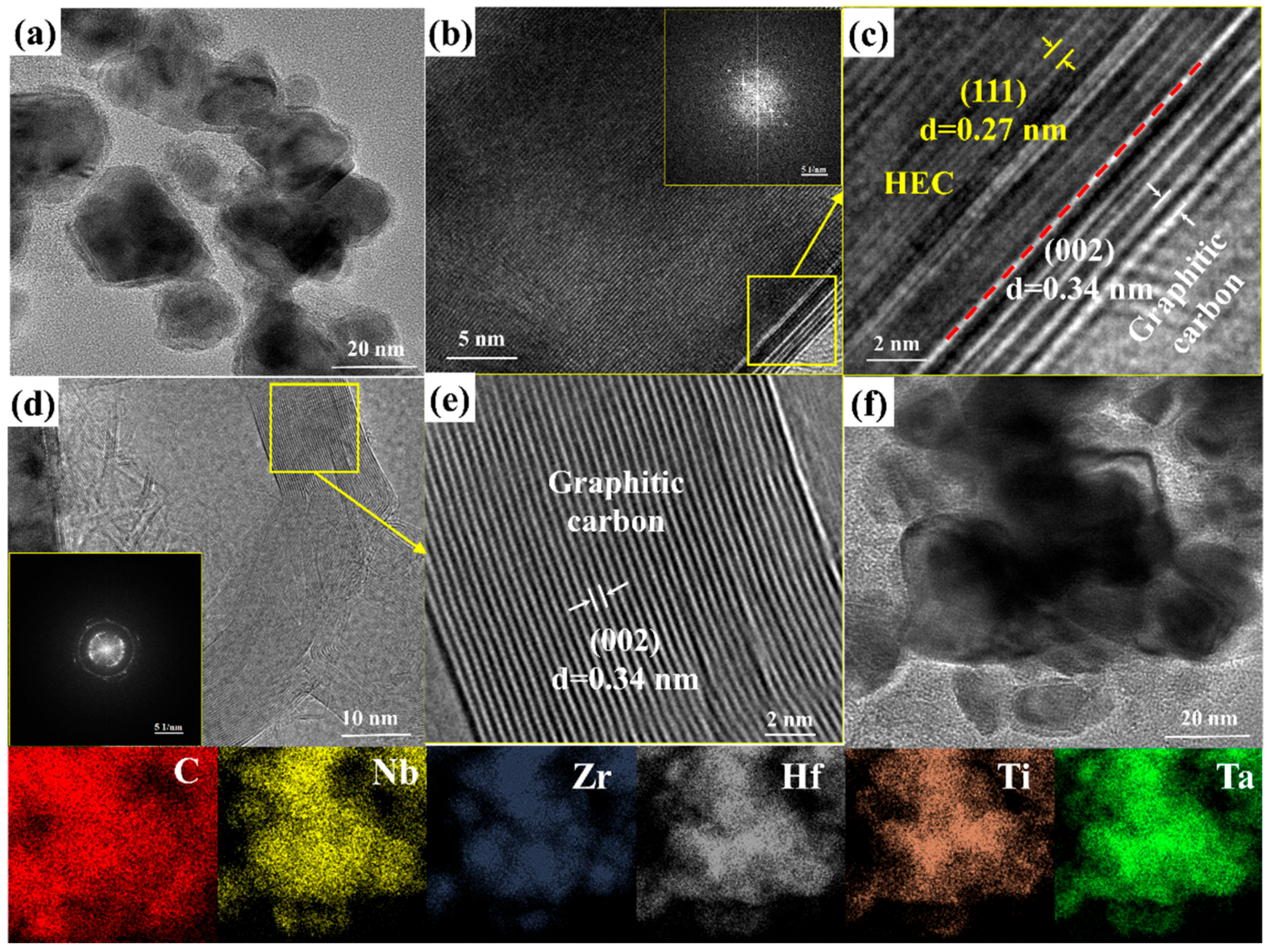
3.1. Synthesis of HEC Powder

The XRD pattern of the synthesized HEC powder is presented in Figure 2a. The five transition-metal elements were essentially completely solid-solved, forming a single HEC phase, with the corresponding diffraction peak at 34.2°. The XRD pattern was further refined by the FULLPROF program. The corresponding refined pattern and parameters obtained through Rietveld analysis are shown in Figure 2b. Obviously, the observed and calculated XRD patterns were in good agreement, and the refinement factor was small, indicating the reliability of the refinement results [26]. The results indicate that the HEC phase in the prepared composite material presented a typical rock salt structure, that is, a face-centered cubic structure. Its unit cell parameters were precisely calculated as a = b = c = 4.528 ± 0.005 Å, α = β = γ = 90°, which were very close to the theoretical value (4.528 ± 0.005 Å) calculated by Ye et al. [27] through first-principles calculations. Figure 2c characterizes the morphology and microstructure of the powder after heat treatment at 1800 °C. After sintering at 1800 °C for 120 min, the HEC powder exhibited a loose accumulation of nanoparticles with a size of ~300 nm, and the particles presented a stepped polyhedral structure composed of multiple helical terraces. Each step presented a nearly hexagonal pattern (Figure 2d). It can be clearly seen from the corresponding EDS-mapping analysis that the five transition metals Ta, Nb, Ti, Zr, and Hf were uniformly distributed at the sub-micron scale, with no obvious elemental segregation (Figure 2e). The atomic percentages of each metal element were close, which was consistent with the experimental design (Figure 2f). Combined with XRD analysis, it is indicated that we successfully synthesized uniform single-phase HEC high-entropy carbide ceramics at 1800 °C.
Figure 3a shows the TEM image of the HEC powder. It can be inferred that the black areas represent HEC grains, while the gray areas between the grains may contain the carbon matrix. The carbon materials formed connections between HEC grains. Most HEC grains were covered with a carbon layer, which was confirmed by the elemental mapping of the HEC grains (Figure 3f). Figure 2b shows the HRTEM image of the HEC grains, which clearly depicts the periodic lattice structure of the HEC, where a set of 0.27 nm stripes corresponds to the (111) crystal plane of the HEC. The calculated lattice parameter was 4.521 Å, which was close to the XRD result (4.520 Å). The HRTEM image of the HEC grains (Figure 3d) also shows that the grains were covered with graphite carbon layers with a lattice of 0.34 nanometers (Figure 3c). The HRTEM image of the carbon region (Figure 3d) shows that the carbon material was composed of graphene sheets with an interconnected structure (Figure 3e). The SAED patterns in Figure 3b and 3d confirm that the HEC phase had a cubic structure, and the carbon materials had a graphite structure. The formation of HEC promotes the transformation of amorphous carbon into graphite carbon, which is very common in the formation of carbides [25,28].

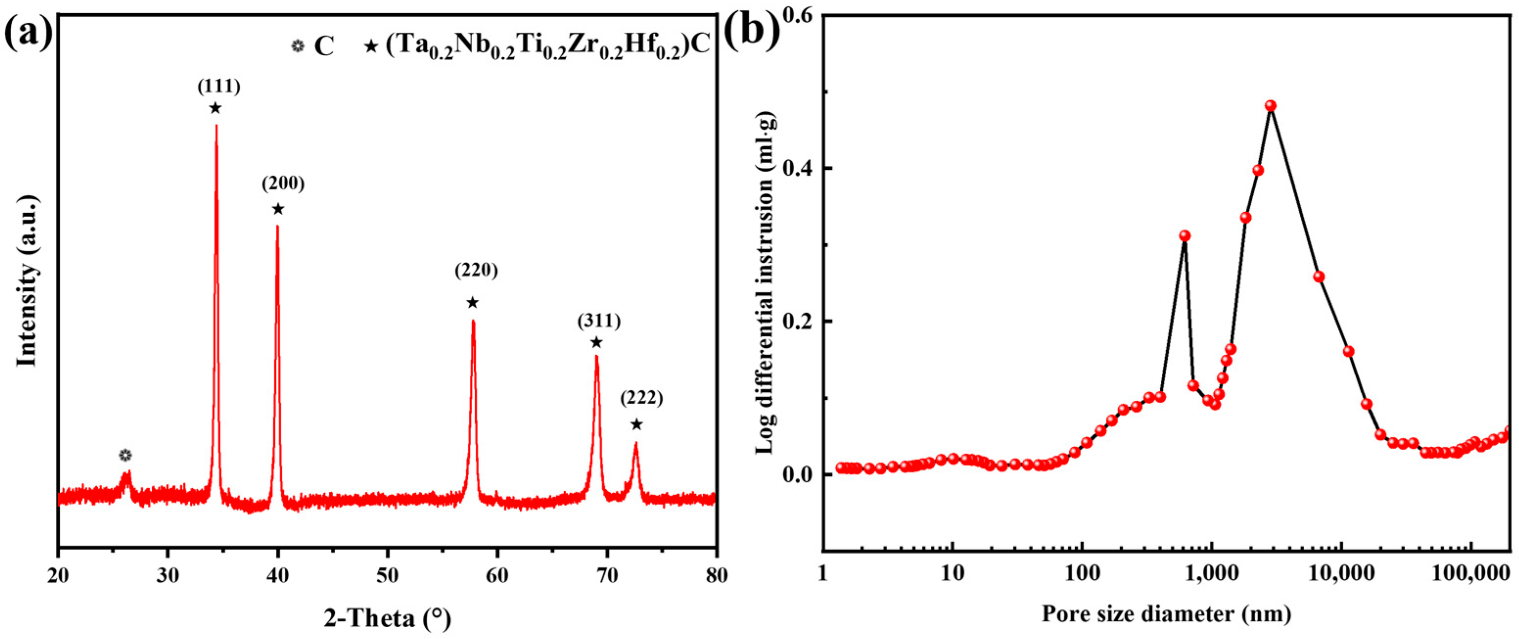
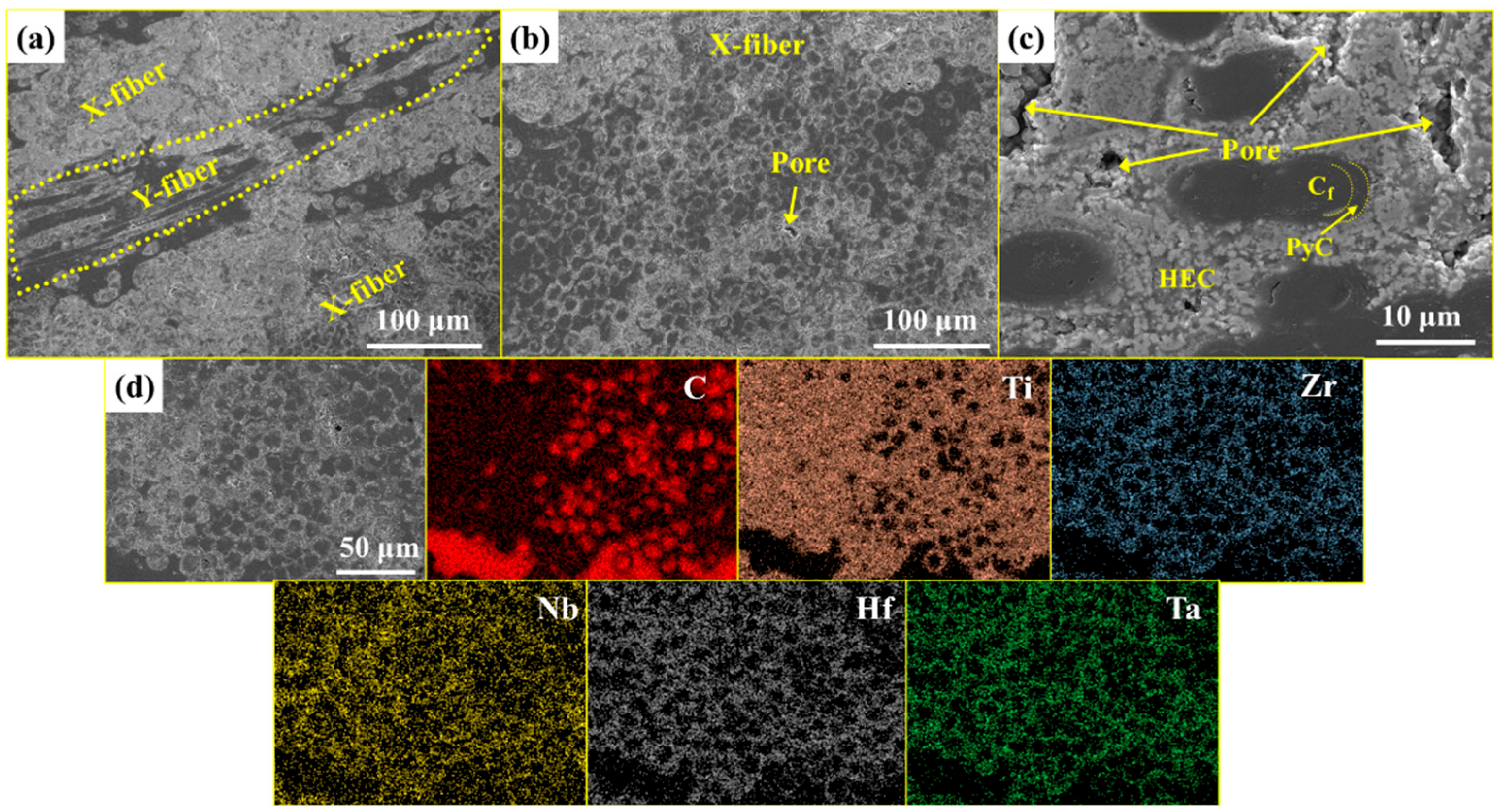
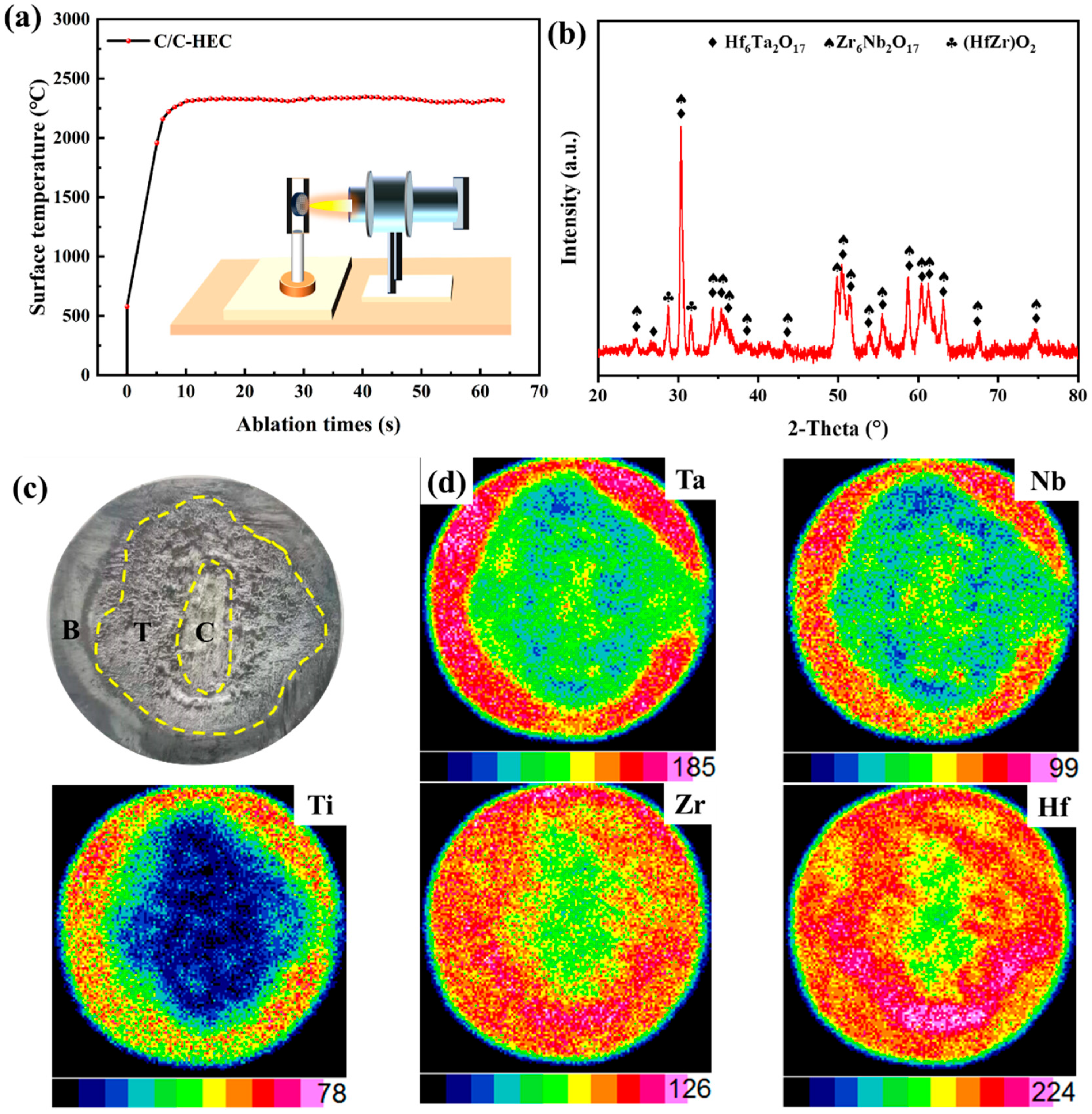
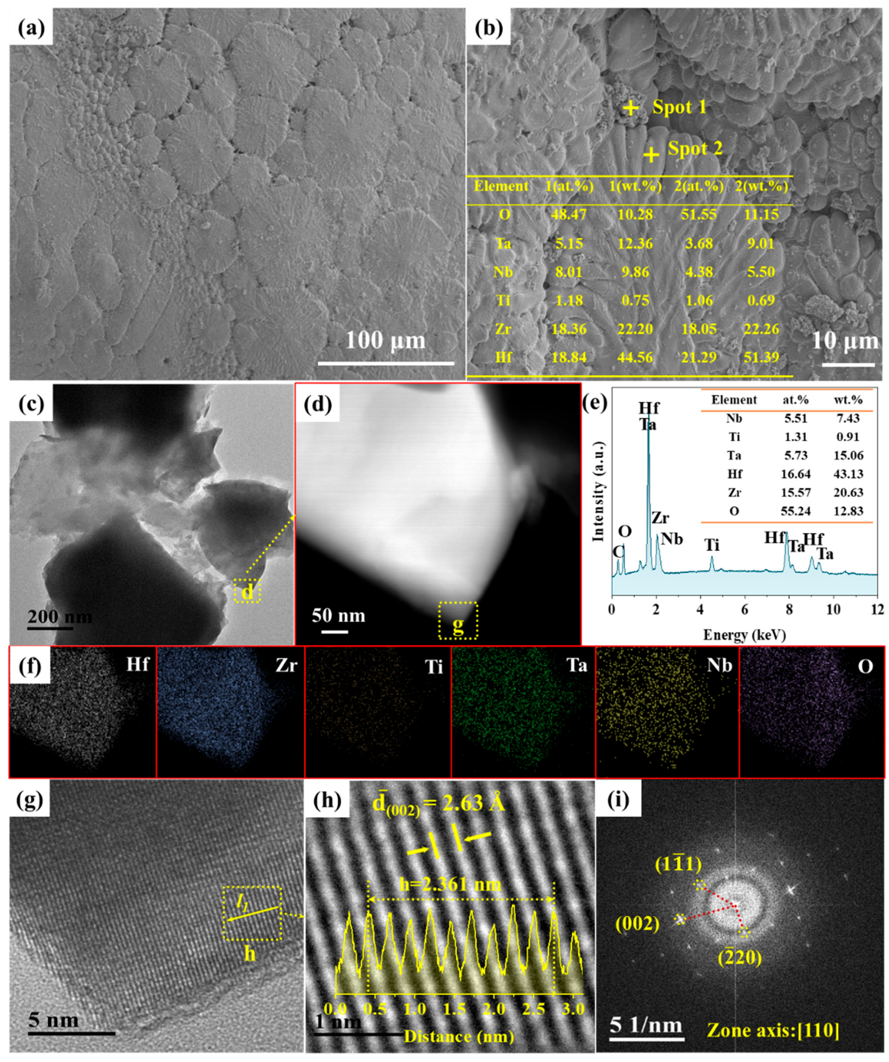
3.2. Phase Composition and Microstructure of C/C-HEC Composites

The XRD pattern of the C/C-HEC composite after sintering at 1800 °C is shown in Figure 4a. The results show that the well-crystallized HEC phase was in situ-generated in the composite material, and its peak was the same as that of the pure HEC powder. In addition, a diffraction peak was observed at 2θ = 26.5°, which can be attributed to the graphite phase. Figure 4b shows the pore size distribution of the C/C-HEC composites after densification by the PIP cycle. Two sub-micron pore diameters existed in the C/C-HEC composite material, approximately 0.8 μm and 2 μm. The volume of the 2 μm pores accounted for over 80% of the total pore volume, indicating that the pores previously sealed by the HEC precursor were forcibly opened during the heat treatment through the release of gases after a process of low-temperature treatment followed by high-temperature treatment. Therefore, these extremely tiny pores or gaps between the fibers could not be well-filled. Detailed information on the pore structure parameters is presented in Table 1.
The SEM analysis of the cross-section of the C/C-HEC composite material is shown in Figure 5a. The black fiber bundles in the X- and Y-directions can be clearly observed, and the white HEC phase fills the spaces between and within the fiber bundles. No obvious pores were found between the fiber bundles. Only some sub-micron pores with diameters ranging from 1 to 2 μm were present in the inner regions of the fiber bundles, as shown in Figure 5b,c, which was consistent with the pore size distribution. This was mainly caused by the gases produced through high-temperature carbothermal reduction. In addition, a distinct PyC interface can be observed at the interface between the carbon fiber and the HEC phase, which can protect the carbon fiber from chemical erosion during high-temperature treatment. The EDS result analysis indicated (Figure 5d) that during the preparation of the composite material, the HEC matrix with a uniform element distribution was effectively introduced. The prepared C/C-HEC composite material had a density of 2.22 g/cm3 and an open porosity of 18.2%.

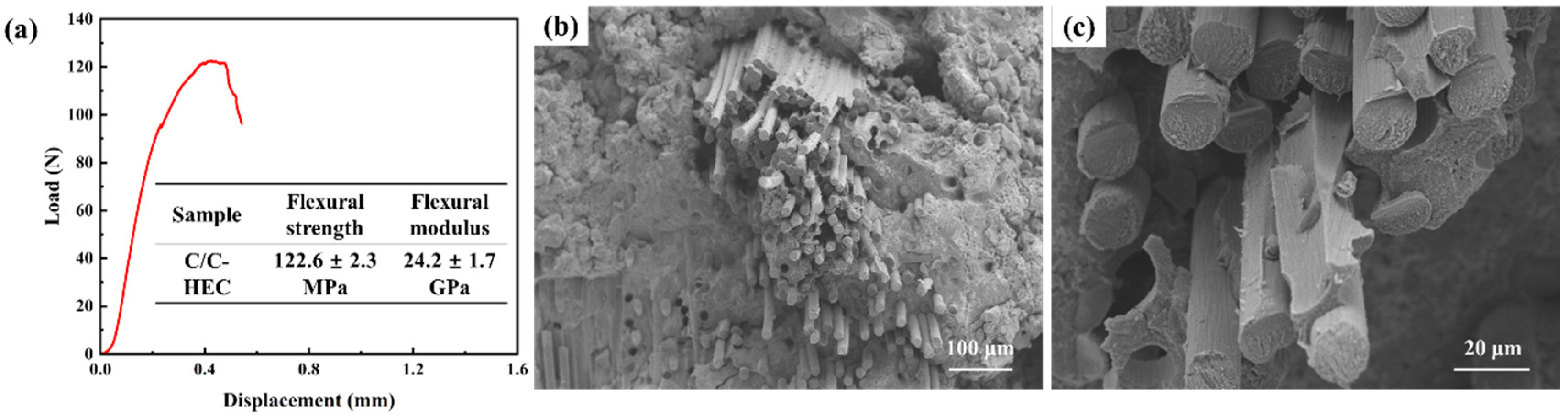
3.3. Mechanical and Ablation Properties of C/C-HEC Composites

The mechanical properties of the C/C-HEC composites were evaluated. Figure 6a shows the load–displacement curve. The initial loading stage shows a linear increase, and after reaching the maximum stress, the curve does not exhibit a sharp decline. This situation is regarded as a typical pseudoplastic fracture, which includes phenomena such as fiber connection, fracture, and pull-out. In addition, this fracture also restricts the further expansion of the crack and, at the same time, weakens the focusing of stress, further consuming the fracture energy it generates. Therefore, the mechanical properties of the composite materials can be enhanced. The flexural strength of this composite material was 122.6 ± 2.3 MPa, and the flexural modulus was 24.2 ± 1.7 GPa. Figure 6c and d show the morphologies of the fracture surfaces of the C/C-HEC composites after the bending test. The thickness of the PyC interface used in this work was approximately 200 nm. Due to the protective effect of the thick PyC interface, the integrity of the fiber interface was not damaged. The fracture of fibers in composite materials is generally a mixture of ductile fracture and brittle fracture. At the outer edge of the fiber bundle, the volume fraction of the HEC phase was large, and its binding force with the fiber was strong, resulting in a small fiber pull-out length (Figure 6b). Obvious fiber debonding and long fiber pull-out could be observed within the fiber bundle (Figure 6c), indicating that the deposited PyC interface was more significant in weakening the fiber–matrix bond strength in the fiber-dense area. The reinforcing effect of fiber-reinforced composite materials depends on the strength of the fibers and the fiber–matrix interface bonding strength. Therefore, it is crucial to regulate the interfacial bonding strength of composite materials to achieve the best match between load transfer and stress dispersion in order to control the strength and toughness of the composite materials. In this work, the random fiber packing state, the matrix distribution state, and the high porosity of the material caused by process characteristics, which are the factors limiting the material strength, could be further regulated.
To simulate the dynamic oxidation behavior of a quasi-real hypersonic service environment, the C/C-HEC composite material was exposed to an oxyacetylene flame for 60 s. Figure 7a shows the variation in the surface temperature of the C/C-HEC composites during ablation. The ablation temperature reached a maximum of 2311 °C and then maintained a dynamic equilibrium. The phase of the ablation zone was identified by XRD, and the results are shown in Figure 7b. The ablation products mainly included Hf6Ta2O17, Zr6Nb2O17, and (HfZr)O2. It is necessary to emphasize that at high temperatures, the diffusion of metals and oxygen is very active, which promotes the formation of a large number of multi-component complex oxide solid solutions. This inevitably leads to the overlap or shift of XRD peaks, making analysis difficult [15]. Therefore, the XRD analysis of the ablation surface only provides possible phase combinations. Figure 7c shows the macroscopic morphology after ablation. According to the degree of ablation in the ablation area, the ablation area can be divided into the ablation center zone (i.e., Zone C), the ablation transition zone (i.e., Zone T), and the ablation edge zone (i.e., Zone B). In the ablation center area, the material was directly exposed to the flame jet, and the surface temperature of the ablation was the highest. Therefore, the ablation phenomenon was most obvious in this area. There was a large amount of white oxidation products and obvious ablation pits in this region. For the over-ablation zone and the ablation edge zone, their distances from the flame center were relatively far, and the included angles were also relatively large. Therefore, the ablation surface temperatures in these two areas were relatively low, and the ablation degree was less than that in the ablation center area. However, mechanical erosion marks caused by high-speed flame scouring could still be found. In the ablation transition zone, there were grey products distributed, and in the ablation edge zone, light grey products appeared. Figure 7d shows the XRF analysis results of the C/C-HEC composite after ablation. According to the elemental distribution on the material surface after ablation, it can be known that after ablation for 60 s under an oxygen–acetylene flame with a heat flux of 2.4 MW/m2, a distinct titanium-poor zone was formed at the ablation center, indicating that the Ti-rich oxides were extremely unstable at high ablation temperatures and volatilized severely in the form of gaseous TiO [29]. In the transition zone and edge zone, the surface temperature decreased, and the content of the five elements was relatively uniform. The mass ablation rate and linear ablation rate of the C/C-HEC composite material are shown in Table 2.
Figure 8 presents the microscopic morphology of the surface ablation central area of the C/C-HEC composite after ablation. As depicted in Figure 8a, a dense molten oxide layer framework was formed on the surface of the ablation central area. This structure significantly inhibited the erosion of the substrate by the flame. Owing to the synergy of oxygen–acetylene flame erosion and the heat conduction direction, distinct radial growth traces were manifested on the surface. Additionally, a small number of cracks and pores were observed at the edges of the molten oxides. According to Figure 8b, a large quantity of fine oxide particles accumulated at the junction of the molten oxide layer. Through elemental analysis, it was found that these particles (Spot 1) were rich in Hf and Zr and contained a small amount of solid-solved Nb and Ta. The composition detection results of the extensive molten oxide area (Spot 2) were close to those of the aforementioned particles, indicating that the molten oxides were formed by the growth of fine particles rich in Hf and Zr. Under the influence of flame scouring and the movement of gaseous products, fine particles tended to aggregate and rapidly sinter and grow at high temperatures, thereby forming a dense oxide layer, demonstrating excellent anti-peeling performance and serving as an oxygen diffusion barrier during the ablation process. To further clarify the structure and composition of the molten oxides, TEM analysis was carried out, as shown in Figure 8c–i. In combination with EDS analysis (Figure 8e,c), the molten oxides contained five metal elements: Zr, Hf, Ti, Nb, and Ta. Among them, the contents of Zr and Hf were much higher than those of Ti, Nb, and Ta, and the content of Ti was the lowest. The ratio of Zr/Hf to Nb/Ta was approximately 3:1. Through HRTEM image measurement (Figure 8g,h), the (002) crystal plane spacing was 2.63 Å, which was close to that of Hf6Ta2O17 (PDF#44-0998; d(002) = 2.6290 Å) and Zr6Nb2O17 (PDF#09-0251; d(002) = 2.6400 Å). The minor difference can be attributed to the solid solution effect of the Hf, Zr, Nb, and Ta elements. Further analysis of the crystal structure information presented in Figure 8i indicated that the molten oxides displayed an orthorhombic structure along the (110) crystal zone axis, which was consistent with the crystal structures of Hf6Ta2O17 and Zr6Nb2O17. This finding aligned with the primary oxide phase identified by XRD (Figure 7b). Therefore, it can be confirmed that the molten oxides were mainly composed of the orthorhombic solid solution phase (HfZr)6(TaNb)2O17. Due to the high vapor pressure of Ti oxides at ultra-high ablation temperatures, Ti was not detected in the oxides.
In summary, under the extremely high temperature of 2311 °C, the C/C-HEC composite material demonstrated outstanding ablation resistance (with a mass ablation rate of 0.67 mg/s and a linear ablation rate of 20 μm/s). This was mainly attributed to the dense (HfZr)6(TaNb)2O17 oxide layer formed on its surface during the ablation process. Specifically, on the one hand, in the high-temperature environment at 2311 °C, the molten (HfZr)6(TaNb)2O17 oxide could effectively seal pores and cracks, and other defects, thereby blocking the diffusion path of oxygen. On the other hand, the high-temperature conditions promoted the sintering and growth of (HfZr)6(TaNb)2O17 oxide particles, eventually forming a continuous and dense oxide protective layer, significantly enhancing the material’s resistance to flame erosion and effectively protecting the substrate.

4. Conclusions

A novel (TiZrHfNbTa)C precursor was synthesized using low-cost transition-metal chlorides and furfuryl alcohol as raw materials. Three-dimensional braided carbon fiber preforms (C/C) coated with pyrolytic carbon (PyC) were used as the reinforcing phase. C/C-(TiZrHfNbTa)C composites were successfully fabricated via the PIP process. This composite material exhibited outstanding mechanical properties (with a bending strength as high as 122.6 MPa) and ablation resistance (with a mass ablation rate of only 0.67 mg/s and a linear ablation rate of only 20 μm/s). The improvement in mechanical properties can be attributed to the strong interface bonding at the outer edge of the fiber bundles and the long-fiber pull-out toughening mechanism induced by the internal PyC interface, while the excellent ablation resistance is attributed to the dense (HfZr)6(TaNb)2O17 oxide layer formed during ablation. This oxide layer not only had excellent anti-peeling and anti-corrosion properties but also effectively acted as an oxygen diffusion barrier during ablation, significantly suppressing further oxidation and ablation reactions within the matrix. This research achievement provides an innovative strategy for the development of low-cost ultra-high-temperature ceramic precursors and opens up a feasible path for the efficient preparation of C/C-(TiZrHfNbTa)C composites.

Author Contributions

Conceptualization, M.H.; validation, J.L. (Jiaqi Liu); formal analysis, Y.L. and L.B.; writing—original draft preparation, T.S. and J.L. (Jiyong Liu); writing—review and editing, H.O. and C.L. All authors have read and agreed to the published version of the manuscript.

Funding

This research was supported by the National Natural Science Foundation of China (Grant No. 52173299, 52372087), and the Natural Science Foundation of Shaanxi Province (Grant No. 2025SYS-SYSZD-062).

Data Availability Statement

All original data from the study have been fully included in the article and further enquiries can be directed to the corresponding author.

Conflicts of Interest

The authors declare no conflict of interest.

References

  1. Ouyang, H.; Zhang, Y.; Li, C.; Li, G.; Huang, J.; Li, H. Effects of ZrC/SiC ratios on mechanical and ablation behavior of C/C–ZrC–SiC composites prepared by carbothermal reaction of hydrothermal co-deposited oxides. Corros. Sci. 2020, 163, 108239. [Google Scholar] [CrossRef]
  2. Li, H.; He, Q.; Wang, C.; Lu, J. Effects of precursor feeding rate on the microstructure and ablation resistance of gradient C/C ZrC SiC composites prepared by chemical liquid-vapor deposition. Vacuum 2019, 164, 265–277. [Google Scholar] [CrossRef]
  3. Zou, X.; Ni, D.; Chen, B.; Lu, J.; Cai, F.; Qin, Y.; Gao, L.; Zhang, X.; Ding, Y.; Dong, S. Ablation behavior and mechanisms of 3D-Cf/Ta0. 8Hf0. 2C-SiC composite at temperatures up to 2500 °C. J. Eur. Ceram. Soc. 2023, 43, 1284–1294. [Google Scholar] [CrossRef]
  4. Xiang, L.; Cheng, L.; Fan, X.; Shi, L.; Yin, X.; Zhang, L. Effect of interlayer on the ablation properties of laminated HfC–SiC ceramics under oxyacetylene torch. Corros. Sci. 2015, 93, 172–179. [Google Scholar] [CrossRef]
  5. Binner, J.; Porter, M.; Baker, B.; Zou, J.; Venkatachalam, V.; Diaz, V.R.; D’ANgio, A.; Ramanujam, P.; Zhang, T.; Murthy, T.S.R.C. Selection, processing, properties and applications of ultra-high temperature ceramic matrix composites, UHTCMCs—A review. Int. Mater. Rev. 2019, 65, 389–444. [Google Scholar] [CrossRef]
  6. Paul, A.; Binner, J.G.P.; Vaidhyanathan, B.; Heaton, A.C.J.; Brown, P.M. Heat flux mapping of oxyacetylene flames and their use to characterise Cf-HfB2composites. Adv. Appl. Ceram. 2016, 115, 158–165. [Google Scholar] [CrossRef]
  7. Paul, A.; Venugopal, S.; Binner, J.; Vaidhyanathan, B.; Heaton, A.; Brown, P. UHTC–carbon fibre composites: Preparation, oxya-cetylene torch testing and characterization. J. Eur. Ceram. Soc. 2013, 33, 423–432. [Google Scholar] [CrossRef]
  8. Akrami, S.; Edalati, P.; Fuji, M.; Edalati, K. High-entropy ceramics: Review of principles, production and applications. Mater. Sci. Eng. R Rep. 2021, 146, 100644. [Google Scholar] [CrossRef]
  9. Shen, T.; Li, C.; Ouyang, H.; He, M.; Li, Y.; Bao, L.; Wang, J.; Chen, Z.; Liu, J.; Zhong, X. A facile fine-grain strategy to fabricate (Ta0.2Nb0.2Ti0.2Hf0.2Zr0.2)C-SiC ceramics with enhanced strength and toughness. Mater. Sci. Eng. A 2025, 929, 148125. [Google Scholar] [CrossRef]
  10. Chen, H.; Xiang, H.; Dai, F.-Z.; Liu, J.; Lei, Y.; Zhang, J.; Zhou, Y. High porosity and low thermal conductivity high entropy (Zr0.2Hf0.2Ti0.2Nb0.2Ta0.2)C. J. Mater. Sci. Technol. 2019, 35, 1700–1705. [Google Scholar] [CrossRef]
  11. Castle, E.; Csanádi, T.; Grasso, S.; Dusza, J.; Reece, M. Processing and Properties of High-Entropy Ultra-High Temperature Car-bides. Sci. Rep. 2018, 8, 8609. [Google Scholar] [CrossRef] [PubMed]
  12. Sun, J.; Zhao, J.; Chen, Y.; Wang, L.; Yun, X.; Huang, Z. Toughening in low-dimensional nanomaterials high-entropy ceramic nanocomposite. Compos. Part B Eng. 2022, 231, 109586. [Google Scholar] [CrossRef]
  13. Li, J.; Lu, F.; Li, T.; Fu, Y.; Zhao, J.; Lv, J.; Zhang, Y. Superior synergistic oxidation resistance of medium-entropy carbide ceramic powders rather than multi-phase carbide ceramic powders. J. Adv. Ceram. 2024, 13, 1223–1233. [Google Scholar] [CrossRef]
  14. Ye, Z.; Zeng, Y.; Xiong, X.; Wen, Q.; Lun, H. Elucidating the role of preferential oxidation during ablation: Insights on the design and optimization of multicomponent ultra-high temperature ceramics. J. Adv. Ceram. 2022, 11, 1956–1975. [Google Scholar] [CrossRef]
  15. Wang, Y.; Zhang, B.; Zhang, C.; Yin, J.; Reece, M.J. Ablation behaviour of (Hf-Ta-Zr-Nb)C high entropy carbide ceramic at temperatures above 2100 °C. J. Mater. Sci. Technol. 2022, 113, 40–47. [Google Scholar] [CrossRef]
  16. Chen, S.; Chen, Z.; Song, W.; Zeng, Y.; Xiong, X. High-temperature ablation behavior and failure mechanism of (Hf0.25Zr0.25Ti0.25Ta0.25)C high-entropy carbide in wide temperature range. J. Eur. Ceram. Soc. 2024, 44, 6815–6826. [Google Scholar] [CrossRef]
  17. Zhao, Z.; Li, K.; Liu, Q.; Li, W.; Zhang, Y. Enhanced anti-ablation performance of carbon/carbon composites modified with ZrC-SiC. Vacuum 2018, 156, 123–127. [Google Scholar] [CrossRef]
  18. Cai, F.; Ni, D.; Chen, B.; Zou, X.; Liao, C.; Gao, L.; He, P.; Ding, Y.; Zhang, X.; Dong, S. Efficient fabrication and properties of 2D Cf/(Ti0.2Zr0.2Hf0.2Nb0.2Ta0.2)C-SiC high-entropy ceramic matrix composites via slurry infiltration lamination combined with precursor infiltration and pyrolysis. J. Eur. Ceram. Soc. 2023, 43, 7403–7410. [Google Scholar] [CrossRef]
  19. Zhang, J.; Zhang, Y.; Fu, Y.; Li, T.; Meng, J. Effect of HfC-SiC transition layer on the ablation resistance of SiC/HfC-SiC/HfC mul-ti-layer coating for C/C composites. Vacuum 2019, 169, 108886. [Google Scholar] [CrossRef]
  20. Fang, C.; Hu, P.; Dong, S.; Feng, J.; Xun, L.; Zhang, X. Influence of hydrothermal carbon coating on the properties of CF/ZrB2/SiBCN prepared by slurry injection. J. Eur. Ceram. Soc. 2021, 41, 84–91. [Google Scholar] [CrossRef]
  21. Cai, F.; Ni, D.; Bao, W.; Chen, B.; Lu, J.; Zou, X.; Qin, Y.; Dong, S. Ablation behavior and mechanisms of Cf/(Ti0.2Zr0.2Hf0.2Nb0.2Ta0.2)C–SiC high-entropy ceramic matrix composites. Compos. Part. B-Eng. 2022, 243, 110177. [Google Scholar] [CrossRef]
  22. Zhang, L.; Wang, W.; Zhou, N.; Dong, X.; Yuan, F.; He, R. Low temperature fabrication of Cf/BNi/(Ti0.2Zr0.2Hf0.2Nb0.2Ta0.2) C-SiCm high entropy ceramic matrix composite by slurry coating and laminating combined with precursor infiltration and pyrolysis. J. Eur. Ceram. Soc. 2022, 42, 3099–3106. [Google Scholar] [CrossRef]
  23. Guo, W.; Hu, J.; Fang, W.; Ye, Y.; Zhang, S.; Bai, S. A novel strategy for rapid fabrication of continuous carbon fiber reinforced (TiZrHfNbTa)C high-entropy ceramic composites: High-entropy alloy in-situ reactive melt infiltration. J. Eur. Ceram. Soc. 2023, 43, 2295–2305. [Google Scholar] [CrossRef]
  24. Sun, B.; Li, C.; Ouyang, H.; Gao, R.; Shen, T.; Li, Y. Synthesis of HfC nanowires on carbon fibers by a novel catalyst-assisted pyrolysis using HfCl4 as precursor. Ceram. Int. 2024, 50, 24901–24906. [Google Scholar] [CrossRef]
  25. Li, C.; Gao, R.; Ouyang, H.; Shen, T.; Chen, Z.; Li, Y. Hierarchical porous (Ta0.2Nb0.2Ti0.2Zr0.2Hf0.2) C high-entropy ceramics prepared by a self-foaming method for thermal insulation. J. Adv. Ceram. 2024, 13, 956–966. [Google Scholar] [CrossRef]
  26. Feng, C.; Zhou, X.; Tao, B.; Wu, H.; Huang, S. Crystal structure and enhanced microwave dielectric properties of the Ce2[Zr1−x(Al1/2Ta1/2)x]3(MoO4)9 ceramics at microwave frequency. J. Adv. Ceram. 2022, 11, 392–402. [Google Scholar] [CrossRef]
  27. Ye, B.; Wen, T.; Huang, K.; Wang, C.Z.; Chu, Y. First-principles study, fabrication, and characterization of (Hf0.2Zr0.2Ta0.2Nb0.2Ti0.2)C high-entropy ceramic. J. Am. Ceram. Soc. 2019, 102, 4344–4352. [Google Scholar] [CrossRef]
  28. Zhang, X.; Yang, X.; Luo, X.; Weng, Y.; Fang, C.; Huang, Q. Formation mechanism of (Ti, Zr, Hf) C medium-entropy carbide derived from polymer precursors and its modification on the ablative mechanism of C/C-SiC composites. Corros. Sci. 2024, 230, 111935. [Google Scholar] [CrossRef]
  29. Chen, Z.; Wang, H.; Li, C.; Ren, K.; Wang, Y. Oxyacetylene ablation of (Hf0.2Ti0.2Zr0.2Ta0.2Nb0.2)C at 1350−2050 °C. J. Eur. Ceram. Soc. 2023, 43, 2700–2707. [Google Scholar] [CrossRef]
Figure 1. Schematic diagram of preparation process of C/C-(TiZrHfNbTa)C composites.
Carbon 11 00041 g001
Figure 2. (a) XRD pattern of HEC precursor after pyrolysis at 1800 °C, (b) refined XRD spectrum, (c) and (d) morphology of powder after pyrolysis at 1800 °C, (e) EDS spectrum corresponding to (c), and (f) the EDAX spectrum, atomic, and mass percentages of each element corresponding to (e).
Carbon 11 00041 g002
Figure 3. (a) TEM image of HEC powder. (b,c) HRTEM images of carbon region; inset shows SAED pattern corresponding to (b). (d,e) HRTEM images of grains; inset shows SAED pattern corresponding to (d). (f) HEC grains and corresponding EDS spectra.
Carbon 11 00041 g003
Figure 4. (a) XRD pattern and (b) pore size distribution curve of C/C-HEC composites.
Carbon 11 00041 g004
Figure 5. SEM and EDS analysis of C/C-HEC composites: (a) SEM images between fiber bundles and (b) within fiber bundles; (c) SEM image of pores within fiber bundles; and (d) elemental distribution.
Carbon 11 00041 g005
Figure 6. (a) Load–displacement curve, (b) fracture surface morphology, and (c) internal fiber morphology of C/C-HEC composites.
Carbon 11 00041 g006
Figure 7. (a) Surface ablation temperature curve, (b) XRD pattern, (c) macroscopic morphology of ablated surface, and (d) XRF analysis of C/C-HEC composites.
Carbon 11 00041 g007
Figure 8. (a) Morphology of ablation center area; (b) morphology and elemental composition of oxides; (c) TEM image; (d) HAADF-STEM image; (e,f) EDAX spectrum, element content, and EDS spectrum; (g,h) HRTEM; and (i) FFT pattern of (g).
Carbon 11 00041 g008
Table 1. Pore structure parameters of C/C-HEC composites.
SampleBulk Density (g/cm3)Porosity (%)
C/C-HEC2.2218.2
Table 2. Mass ablation rate and linear ablation rate of C/C-HEC composites.
SampleMass Ablation Ratio (mg·s−1)Line Ablation Ratio (mm·s−1)
C/C-HEC0.6720
Disclaimer/Publisher’s Note: The statements, opinions and data contained in all publications are solely those of the individual author(s) and contributor(s) and not of MDPI and/or the editor(s). MDPI and/or the editor(s) disclaim responsibility for any injury to people or property resulting from any ideas, methods, instructions or products referred to in the content.

