Article

Flow Performance Analysis of Non-Return Multi-Door Reflux Valve: Experimental Case Study

by
Xolani Prince Hadebe
*,
Bernard Xavier Tchomeni Kouejou
,
Alfayo Anyika Alugongo
and
Desejo Filipeson Sozinando
Department of Industrial Engineering, Operation Management, and Mechanical Engineering, Vaal University of Technology, Andries Potgieter Blvd., 1900, Private Bag X021, Vanderbijlpark 1911, South Africa
*
Author to whom correspondence should be addressed.
Fluids 2024, 9(9), 213; https://doi.org/10.3390/fluids9090213
Submission received: 4 August 2024 / Revised: 7 September 2024 / Accepted: 10 September 2024 / Published: 12 September 2024
(This article belongs to the Special Issue Computational Fluid Dynamics in Fluid Machinery)

Abstract

Non-return multi-door reflux valves are essential in fluid control systems to prevent reverse flow and maintain system integrity. This study experimentally analyzes the flow performance of multi-door check valves under different operating conditions, focusing on pressure testing and evaluating their effectiveness in preventing backflow. A wide-ranging experimental setup was designed and implemented to simulate real-world scenarios, facilitating accurate measurement of flow rates, pressure differences, and valve response times. The collected experimental data were analyzed to evaluate the valve’s performance in terms of flow capacity, pressure drop, and hydraulic efficiency. Additionally, the effects of factors such as valve size, valve configuration, and fluid properties (water) on performance were considered. It was found that the non-return multi-door reflux valve has been proven effective and reliable in preserving system integrity and maintaining unidirectional flow at the same time during pressure testing. It exhibits no backflow, remains stable and constant across varied flow conditions, and demonstrates a low pressure drop and high flow capacity, making it suitable for critical pressure testing applications. The response curve revealed that valve opening takes longer to reach higher flow rates than closing, indicating pressure instability during transition periods. This non-linear relationship indicates possible irregularities in pressure drop response to flow rate changes, highlighting potential areas for further investigation.

1. Introduction

In the field of fluid dynamics and pipeline engineering, valve efficiency and reliability play a crucial role in maintaining optimal system performance. One such valve that has gained attention for its unique design and functionality is the multi-door non-return reflux valve. The check valve is one of the most important components of any fluid flow system. This valve is specially designed and manufactured to allow unidirectional flow while preventing backflow into pipelines [1], ensuring system efficiency and maintaining system integrity. There are, however, numerous limitations to using these devices, including the presence of water hammer effects, a limited ability to withstand high pressures, and issues with debris accumulation, which, together, can reduce their overall effectiveness at preventing backflows [2]. In a wide range of applications, the multi-door check valve is considered to be one of the most reliable and efficient types of check valve among the different types available. Performing pressure testing is also one of the most important aspects of valve performance analysis, as it provides valuable information on how valves perform under different operating conditions and under different load conditions. When it comes to multi-door reflux valves, this is of particular importance as they must be able to operate effectively under high pressures as well as prevent backflow [3].
Experimental studies provide significant validation of computational fluid dynamics (CFD) simulations and offer insight into real-world performance under various operating conditions. Experimental setups involve flow devices or test loops where check valves are subjected to varying flow rates, pressures, and fluid properties. Performance parameters such as pressure drop, flow coefficient, and cavitation potential are measured to evaluate the efficiency and reliability of the valve under different operating conditions. Researchers conducted various experiments to evaluate the hydraulic behavior and functional characteristics of check valves. One of the recently published studies on multi-door reflux valves was conducted in [4,5], where experiments for studying the flow characteristics of a multi-door reflux valve using water as the working fluid were conducted. Results showed that the valve had good flow control and that the pressure drop across the valve was relatively low. The valve was found to effectively maintain a constant liquid level in the column. Another early study on the flow performance of multi-door reflux valves was conducted in [6]. The authors derived a mathematical model to simulate the flow characteristics of the valve and validated it with experimental data. They found that the flow rate through the valve increased as the number of doors increased, and the valve could achieve a higher degree of reflux separation with more doors. Based on a previous study [6], Chen also investigated the effect of door orientation on the performance of multi-door reflux valves [7]. The results proved that orienting the doors perpendicular to the flow direction improves the flow coefficient by 15% (which represents the flow capacity of the valve) compared to parallel orientation. Furthermore, the effect of the door shape on the performance of multi-door reflux valves was also investigated in [8]. The results demonstrated that using a curved door instead of a flat door improves the flow coefficient by 10% due to the reduction in turbulence caused by the curved door.
Recently, Dincer and Kaya investigated the performance of a multi-door reflux valve using numerical and experimental techniques [9]. They found that the valve had strong flow control, and the pressure drop across it was relatively small. They also observed that the valve effectively maintained a constant liquid level in the column and could operate over a wide range of flow rates. Similarly, another experimental study was conducted to investigate the performance of a multi-door reflux valve under different working conditions [10]. The author demonstrated that the valve flow coefficient increased with the number of doors and the valve opening angle. The study also showed that valve performance was influenced by Reynolds number and pressure drop. Extraction and identification of fault features in a non-viscous medium proved to be complex due to fluid obstruction and required the use of appropriate signal-processing tools [11]. One of the studies on the experimental dynamic characteristics of check valves was developed by [12]. They conducted a series of valve flow tests at the Utah Water Research Laboratory in Logan. Several types of eight-inch check valves were tested for water flow under dynamic conditions. The check valves were installed in a horizontal test pipe and subjected to different initial forward-flow rates and varying rates of flow reversals. The laboratory was powered by a natural supply of mountain runoff from a reservoir via a 121.92 cm pipeline, so speeds of between 4 and 609.6 cm per second were easily achieved. The laboratory was also equipped with a certified weighing system to record flow rates. The pressure drop of the valves was read using pressure gauges and the dynamic pressures were recorded using transducers and a high-speed data logger. The results indicated that the best check valves are the nozzle check valve, double disc check valve, surge buster, and silent check valve, all of which feature assisted closing by spring. Other best non-slamming check valves are the Swing-Flex Check Valve and Angled Disc Check Valve, which feature an angled seat and short stroke. Long-stroke, springless valves, ball, and swing valves, have the greatest potential for slamming.
The static and dynamic characteristics of a nozzle check valve were also studied in [13] where the check valve was mounted in the test circuit and, initially, the static characteristics were determined. In addition to the flow coefficient, the position of the disk was observed with the camera. For the determination of the dynamic characteristics, the flow deceleration was induced with the dynamometer which braked the pump. The maximal deceleration rate was 7.3 m/s2. The results obtained were compared to the results presented in [14]. Unlike the static characteristic, the measurement of the dynamic characteristic is not covered in the standards. Several authors use different approaches to the measurement and evaluation [15,16,17]. Defining the deceleration rate dv/dt was crucial in their case. The authors decided to use two clearly identifiable points: the moment when the dynamometer torque is zero (the pump begins to brake) and the moment when the reverse flow is maximum (the disc hits the seat). This is one of the reasons why the results of [18] vary considerably. Although the importance of check valves is well recognized, a detailed understanding of their flow characteristics is essential to optimize their use in various industrial applications. The multi-door reflux check valve features multiple hinged doors that close when water flow is reversed, preventing water or contaminants from flowing back and opening in response to fluid flow. However, the effectiveness of this valve in real-world scenarios has not been studied extensively. In Southern Africa, access to full analysis of experimental work and relevant information is restricted to researchers, and without the necessary facilities to carry out experimental work, researchers continually face challenges in the local performance analysis flow rate of multi-door check valves. This experimental study aims to fill this knowledge gap by providing a comprehensive and in-depth experimental analysis of the flow performance of a multi-door check valve designed and manufactured locally in South Africa, to provide valuable perceptions of its operational characteristics and comprehensive test results. Therefore, the present experiment aims to evaluate the performance of the multi-door check valve under various pressure test conditions, focusing on its ability to maintain system integrity, prevent backflow, ensure stable and consistent operation under different flow conditions, and evaluate its pressure drop and flow characteristics. The objective is to determine the suitability of the valve for critical applications requiring reliable unidirectional flow and minimal pressure loss.
This work is divided into five sections, the description of the design and the operation of the valve is discussed in Section 2. In Section 3, the experimental setup is established, detailing the methodology to be used. Section 4 presents the experimental flow analysis for each specific set of parameters, followed by the valve flow performance results from the first and second test attempts, as well as an overall summary of the experimental results. This article concludes with viewpoints in Section 5.

2. Valve Description

The valve under investigation is a multi-door non-return flow valve intended for retrofit. The initial design of the valve is not that of AVK Valves South Africa; AVK Valves is solely responsible for the structural analysis and modification for the optimal operation of the valve. The valve features several hinged doors designed to allow flow in one direction while preventing any reverse flow (Figure 1a). It is designed to allow unidirectional fluid flow while blocking reverse flow. The multi-door reflux valve used as shown in Figure 1b is a commercially available model, whose specifications meet industry standards such as, ANS B16.5, and AWWA C207, where the geometric characteristics of a multi-door valve used in the experiment and other relevant features are given in Table 1.

Design and Operation

Unlike traditional check valves, the multi-door check valve is a sophisticated engineering solution designed to address the challenges associated with backflow in pipelines. This valve incorporates multiple doors that open and close in response to changes in flow direction [15]. The design aims to minimize pressure loss, reduce the effects of water hammer, and improve overall system efficiency. The multiple doors inside the valve are strategically positioned to allow fluid to flow in one direction while preventing reverse flow (Figure 2a). The valve typically consists of a sturdy body made from ductile iron materials (Figure 2b), ensuring durability and corrosion resistance. The doors are hinged and respond dynamically to changes in flow speed, ensuring efficient operation in a variety of conditions (Figure 2a).

3. Experimental Parameters

Several parameters are considered during the experimental analysis:
  • The valve is exposed to increasing pressure to evaluate its ability to withstand high-pressure conditions without leaking or damage.
  • The primary objective is to evaluate how the multi-door reflux valve preventer influences forward flow and its ability to prevent backflow.
  • The pressure drop across the valve is measured to assess the resistance the valve imposes on the fluid flow. This is crucial to determine the impact of the valve on the overall system pressure and evaluate the effectiveness of the valve in minimizing energy losses.
  • Simulated backflow conditions are created to examine the effectiveness of the valve in preventing backflow. Emphasis is placed on understanding the response of the valve to abrupt changes in flow direction.
  • The response time of the multi-door reflux valve is analyzed to evaluate how quickly the valve closes when the reverse flow is detected. A rapid response time is essential for effective reflux prevention.
  • The multiple doors are designed to create a robust barrier against reverse fluid flow. The reliability of the sealing mechanism is evaluated through repeated opening and closing cycles. This is a simulated real-world condition in which the valve operates continuously over an extended period.
  • Different materials and design variations of the multi-door configuration are tested to evaluate their impact on flow performance and sealing effectiveness. This analysis aims to identify the most appropriate materials and design parameters for optimal valve performance. The durability of the materials used in the construction of the valve is evaluated to ensure that the valve can withstand long-term use without degradation.

3.1. Multi-Door Reflux Valve Experimental Setup and Methodology

To evaluate the flow performance of the multi-door reflux valve, a complete experimental setup is carried out in an established and controlled test bay section as shown in Figure 3. The test bench consists of a closed-loop piping system with the test section containing the valve installed at a critical point (Figure 3b). Flow rates are controlled using a pump and pressure sensors have been strategically placed to measure pressure differences across the valve under various conditions of water pressure and valve response, with a particular emphasis on pressure testing and the effectiveness of backflow prevention (Figure 3a).

3.1.1. Test Pressure

This procedure covers the pressure testing of the multi-door reflux check valve. The valve body, doors, and sealing are tested using a motorized pump test bench to determine the integrity of castings and assembled valve. The testing procedure includes a valve body test, an assembled door strength test, and a valve door and valve seat tightness test.

3.1.2. Testing Equipment

The experiment used water as the test fluid to simulate a real-world scenario. The choice of water ensured that the results would be relevant to a wide range of applications, including drinking water supply systems and industrial processes. The experimental setup includes a closed-loop system in which the valve is installed. The setup allows precise manipulation of flow conditions using testing instruments such as the following: (1) a motorized pump test rig (Figure 4a); (2) a test plate (temporary sealing device that is bolted onto the flange connection of the valve to isolate the valve from the rest of the system during testing (Figure 4b)); (3) blank flanges or cover plate (used as a drain plug with a tapped-hole air release plug highlighted in red on Figure 4c; (4) two off-certified calibrated pressure gauges–glycerin filled 0 to 25,000 kPa located at the valve inlet (Figure 5a) and outlet (Figure 5b), respectively.
These instruments are strategically placed at various points along the test pipeline.

3.2. Body and Doors Strength Test

The strength test of the valve body and doors is carried out on the valve body and doors. The test is used to verify the integrity of the casting in an assembled condition of the valve at 2 × the valve pressure rating, which will give a test pressure of 3500 kPa over 15 min (Figure 6). Under pressure, there should be no visible leaks between the test plates and the valve body flanges, and there should be no sweating through the casting “wall” (porosity).

3.2.1. Setup Procedure for Body and Door Strength Test

To assemble the multi-valve check valve, the test plates were first attached to the two pipe flanges of the valve body using flange bolts (Figure 6). Next, the blanking flanges were attached to the upper and lower inspection covers of the inlet and outlet of the valve body (Figure 1a). The valve body was then supported as if it were being installed in a horizontal pipe stack, after which the isolation ball valve was connected to the lower test plate upstream and downstream of the valve. The incoming water pressure pipe was attached to the isolation ball valve and the motorized pump, ensuring a certified pressure gauge was connected to the pump as highlighted in Figure 5. The doors were partially opened to allow water to fill the bodywork above and below the doors for full-flow performance analysis (Figure 2b). Finally, the valve doors were closed in the seated position, and the door seal was prepared by allowing the counterweights to descend into the closed position (Figure 1b).

3.2.2. Commencing of Body Strength Test Procedure

To ensure the integrity and reliability of the non-return multi-door reflux valve under high-pressure conditions, some crucial steps were performed: first, the isolation ball valve on the incoming test plate was opened, and the motorized pump was started to flow water into the valve body until it was filled, allowing air to escape through the connection point on the upper test plate (Figure 7). A pressure gauge was then connected to the top test plate, and the water pressure was gradually increased to 3500 kPa, ensuring that both pressure gauges registered 3500 kPa. All air was removed from inside the valve, the isolation ball valve was closed, and the motor pump was stopped. The pressure was maintained inside the valve body and the upstream side of the doors for at least 15 min, checking for excessive leaks at the flanges, end covers, U-joint, and gland rings. If excessive leakage was visible, the pressure was reduced by opening the isolating ball valve. The test pressures on the gauges were recorded at the beginning and end of the test, checking for leaks at the valves and blanking flanges. Finally, the valve body was inspected for sweating or leaks through the walls, and any leaks were marked with a permanent white marking pen.

3.2.3. Terminating the Body Strength Test Procedure

The following experimental procedure was designed to safely and efficiently complete the strength test of the multi-door check valve body by releasing internal pressure and draining the system to prevent damage and prepare for any subsequent testing or inspection. The process began with opening the isolation ball valve to release the pressure. Then the water pressure at the motor pump was released. The incoming pressure pipe fitting was then removed, and the valve was emptied of all water. This ensured that the valve was safely depressurized and drained, ready for any subsequent testing or inspection.

3.3. Valve Seal and Leak Test—Body and Doors

This test is performed after the assembly of the valve complete with lever and weights. The test serves to verify the effective sealing of the assembled valve at its seat faces. The test pressure is at 1.1 times the rated pressure of the valve—1925 kPa, for a minimum period of 10 min. Under pressure, no leaks should be visible between the test plate and the valve body flange.

3.3.1. Setup Procedure and Door Seat Leak Test

The non-return multi-door reflux valve was first assembled, followed by fastening test plates onto the valve pipe flanges of the body using flange bolting. Blanking flanges were then fastened onto the top and bottom inspection covers of the valve body inlet and outlet. The valve body was supported as if installed in a horizontal pipe column. An isolating ball valve was connected to the bottom test plate on both the upstream and downstream sides of the valve. The incoming water pressure hose was connected to the isolating ball valve and the motorized pump. Only the incoming pressure side test plate was used, with the opposite end test plate removed and the isolation ball valve connected to the pressure gauge fitting. Finally, a pressure pipe was connected to the isolation ball valve and the valve doors were closed to the seated position.

3.3.2. Commencing of Body and Door Seat Leak Test

The start of the door body and seat seal test was to fill the valve with water and gradually increase the pressure to check the sealing capabilities of the valve components under specific conditions. The procedures were presented as follows: (a) First, the valve was filled with water through the inspection cover door in the outlet part of the body, and the motorized pump was started. (b) The water pressure was progressively increased to the prescribed value of 1925 kPa, ensuring that the lower gauge on the test plate and the pump gauge registered this pressure. (c) This pressure was maintained between the valve body and the upstream side of the doors for at least 10 min. (d) Leaks were checked at the valve flanges, end covers, and especially at the door seat, where there should have been no leaks between the door seats and the body seat.

3.3.3. Terminating the Body and Door Seats Leak Test

To complete the body strength test by relieving pressure and ensuring all connections are properly disconnected, the following procedure was followed: First, the isolation ball valve was opened to release any remaining pressure. Then, the water pressure was released at the motorized pump. Afterward, the inlet pressure pipe was disconnected. Finally, the remaining water from the valve was drained to complete the process.

4. Results, Analysis, and Discussions

Pressure testing involves subjecting valves to various pressures within specified limits, following industry standards such as ASTM A216 [19], ASTM A351/A351M-00 [20], and ISO 17292, 5208, 5752 & 7259 [21], and using cyclic testing to simulate real-world conditions.

4.1. First Test Attempt

The first attempt at an experimental pressure test of a multi-door check valve, aimed at evaluating its performance under various conditions, revealed unexpected leaks during the testing phase, raising concerns about its reliability and safety in practical applications.

4.1.1. Body and Door Structural Pressure Test

With the doors in the open position, and then the doors in the closed position, the pressures in Table 2 were applied to the valve body, for a minimum period of 15 min. For door testing, the other side of the valve was exposed to atmospheric pressure. There was no visual plastic deformation or distortion of the valve body, doors, and seal supports. Leakage at pressure-containing joints was not the cause for failure of the test.

4.1.2. Body and Door Seat Leak Pressure Test

With the doors in the closed position, the pressures in Table 3 were applied to the upstream side of the valve for a minimum period of 5 min. The other side of the valve was at atmospheric pressure. The allowable leak rate past the valve seats exceeded 42 mL/min. There was another visible leak on the lower shaft bearing hub.

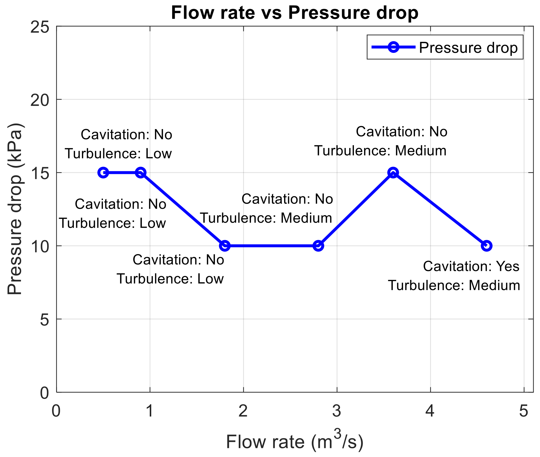
4.1.3. Flow Performance and Pressure-Drop Test

Due to the high leakage shown in Table 3, the pressure drop in Figure 8a highly increased, hence hindering the performances of flow and the prevention of backflow in a multi-door reflux valve. The results of pressure drop were so high due to failing valve operation; hence the valves were not able to control the fluid well, as displayed in Figure 8b.

4.1.4. Flow Performance and Cavitation Test

Figure 9 shows the significant effect that cavitation has on the flow performance of the valve due to high-pressure drop; it brings about damage to the seat arrangement area and hence disrupts the ability to effectively seal.

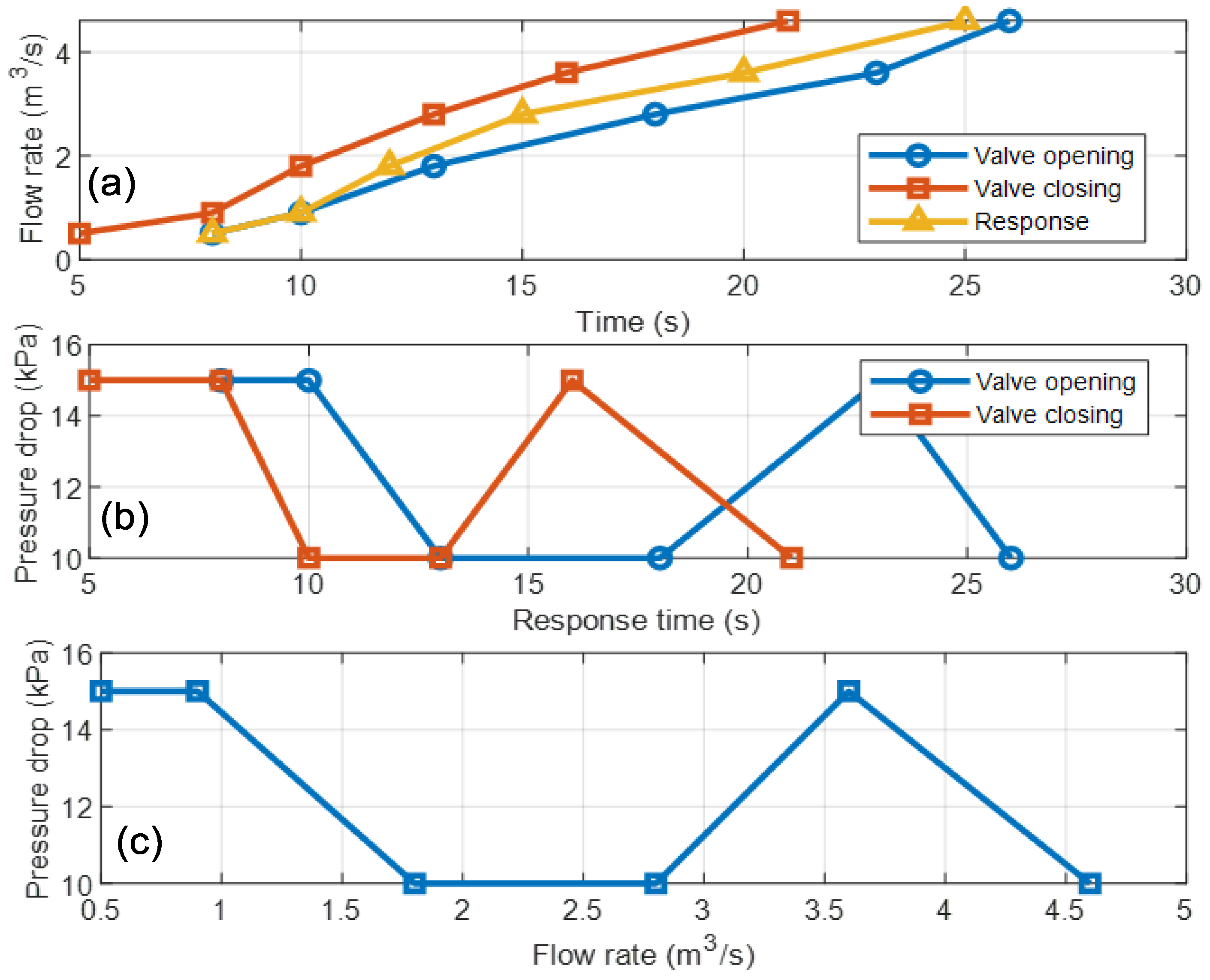
4.1.5. Flow Performance and Response Time

The outcome in Figure 10 presents the fact that high leakage levels, as presented in Table 3, resulted in the high-pressure drop, hence affecting adversely the response time of flow performance of a multi-door reflux valve. As for highly leaked ones, it jeopardizes quick response and efficient valve performance. As a result, it leads to slower actuation of the valve and the reduced performance of the overall system. In addition, under various operating circumstances, the linear pressure decreases with increasing flow rates demonstrating superior fluid dynamics control and stability.

4.1.6. Observed Failures

During the experimental pressure testing, unexpected leaks were observed at several locations of the non-return multi-door reflux valve (Figure 11). This leak, perceptible even at small pressure differences, highlighted problems with the sealing mechanisms. This occurred around the valve seat sealing surfaces and at the lower door shaft bushings, persisting even at pressures below the valve’s rated capacity. This significant leak raised concerns about the valve’s reliability and effectiveness in preventing backflow.

4.2. Root Cause Analysis

Factors that contributed to the failure observed during the pressure testing are as follows:
  • Material Deficiencies
The sealing surfaces, body seat (Figure 12a), and door seat (Figure 12b) of the reflux valve are constructed using stainless steel, known for its corrosion resistance and durability. Stainless steel is a common choice for applications involving fluid handling due to its excellent mechanical properties and corrosion resistance, but during routine operation, leakage was observed at the sealing surfaces of the valve. The leakage was consistent and occurred regardless of the operational conditions, suggesting a fundamental issue with the stainless steel-to-stainless steel interface.
Factors contributing to the failure of stainless steel-to-stainless steel sealing surfaces include the following:
  • Imperfections on the sealing surfaces occurred during manufacturing, compromising the ability of the surfaces to form a tight seal (Figure 12a).
  • The repetitive motion during operation caused the sealing surfaces to gall and gouge, thus damaging the sealing surfaces, and preventing them from effectively sealing (Figure 12b).
  • Leakage points were identified around the doors, suggesting inadequacies in the sealing mechanisms, potentially linked to design and manufacturing defects. Observations during operation and subsequent disassembly revealed misalignment of the shaft ring, resulting in uneven contact and wear of the sealing surfaces. This misalignment contributed to increased friction and ultimately leakage during experimental pressure tests, as shown in Figure 13.
Factors that contributed to the misalignment of the shaft bush and subsequent failure of the sealing surfaces:
  • Inconsistent manufacturing tolerances in producing the valve components led to misalignment between the shaft bush and the sealing surfaces.

Corrective and Preventive Actions (Material Improvement)

To address the identified issues and prevent similar failures in the future, the following corrective and preventative measures have been implemented:
  • The manufacturing process has been enhanced to guarantee a smoother, more uniform surface finish on the stainless steel sealing surfaces, and to keep consistent tolerances and accurate alignment of the shaft ring with the sealing surfaces.
  • The door sealing material has been replaced with a soft metal such as AB1 aluminum bronze, which will improve galling and corrosion resistance, thereby improving the longevity and effectiveness of the sealing surfaces compared to 316 stainless steel. In this context, 316 and AB1 refer to specific characteristics of the materials.
  • A further series of pressure tests were performed on the improved valve to verify the effectiveness of the implemented recommendations and ensure that the valve meets or exceeds industry standards

4.3. Second Test Attempt and Re-Testing

The second experimental analysis after implementing the recommended improvements provided significant information on the valve’s flow performance. The valve demonstrated a robust ability to handle varying flow rates, maintaining effective sealing over the entire range. The pressure drop was within acceptable limits, highlighting the minimal impact of the valve on the overall system pressure. Testing of the valve also revealed the durability of the sealing mechanism, with the valve consistently maintaining its performance over extended operating cycles. The backflow prevention capabilities are particularly impressive, highlighting the valve’s suitability for applications where fluid reversal is a critical concern.

4.3.1. Body and Door Structural Pressure Test

With the doors in the open position and then the doors in the closed position, the pressures listed in Table 4 were applied to the valve body for a minimum of 15 min. For the doors test, the other side of the valve was exposed to atmospheric pressure. There was no visual plastic deformation or distortion of the valve body, doors, or seal retainers. Leakage at pressure seals was not the cause of test failure.

4.3.2. Body and Door Seat Leak Pressure Test

With the doors closed, the pressure listed in Table 5 was applied to the upstream side of the valve for a minimum of 5 min. The permissible leakage rate beyond the valve seats was not to exceed 42 mL/min.

4.3.3. Flow Performance and Pressure Drop Test Results

Due to the low leakage demonstrated in Table 5, the pressure drop in Figure 14 is very low, thereby improving flow performance and backflow prevention in a multi-door reflux valve. The results of such a low-pressure drop allowed for the efficient operation of the valve and its ability to control the fluid very well.

4.3.4. Flow Performance and Cavitation Test Results

Figure 15 shows low and medium results of cavitation due to tight sealing and low-pressure drop. After corrective and preventive actions, the effect of low and medium cavitation on flow performance shows that the pressure losses in this case remained relatively low, fluctuating between 8 kPa and 15 kPa when the flow rate varied between 1 and 5 m3/s. Cavitation does not occur until the highest flow rate (5 m3/s), and even in this case the pressure loss only reaches 15 kPa, indicating a perfect seal with minimal cavitation and turbulence.

4.3.5. Flow Performance and Response Time Results

Figure 16 below shows that a low leakage rate in a multi-gate reflux valve has a great influence on the flow performance response time. The result is that generally low leakage rates improve valve sealing with minimal unwanted backflow, and closure is rapid when necessary. In return, this provides better response times, leading to improved overall system efficiency and stability.

4.3.6. Discussion

The experiment evaluated a valve’s performance under different scenarios, including varying flow rates and sudden changes in direction. The pressure drop across the valve was a key measurement, as it directly influences the efficiency of the pipeline system. The valve design reduced turbulence, resulting in energy savings and system life. The valve’s robust construction and efficient operation make it a promising solution for applications in water distribution, sewage systems, and industrial processes. The failure analysis of stainless steel-on-stainless steel sealing surfaces of multi-door reflux valves indicates surface finish, galling, and material incompatibility issues. Implementing recommended improvements in manufacturing, material selection, and operational monitoring was essential to ensure the sealing surfaces’ reliability and the reflux valve’s overall performance. The valve demonstrated minimal leakage even at high pressures, confirming its robust performance. Flow analysis demonstrated the valve’s adaptability to changing conditions, maintaining stable flow rates and preventing backflow. Material compatibility testing showed minimal wear and corrosion, demonstrating the valve’s durability.
A comparative analysis showed the following: The results of the flow and pressure drop performance tests showed that the pressure difference between the inlet and outlet is consistently high (about 100 kPa), which is detrimental to the flow performance and backflow prevention in a multi-gate backflow valve. The pressure loss adjustment line confirms a nearly linear relationship, indicating that for every 1 m3/s increase in flow, the pressure loss increases by about 10 kPa (Figure 8).
The flow performance and response time in Figure 10 revealed that the valve takes longer to open to reach higher flow rates than it does to close, indicating pressure instability during transition periods. This non-linear relationship indicates possible irregularities in the pressure drop response to flow rate changes, thus negatively affecting the flow performance response time of a multi-gate reflux valve. As a result, this leads to slower valve actuation and reduced performance of the overall system, highlighting potential areas for further investigation [22]. Regular maintenance is therefore recommended for consistent performance. Furthermore, the flow performance and pressure drop test results show that the pressure difference between the inlet and outlet is consistently low (approximately 10 kPa), indicating efficient valve operation with minimal pressure loss. The pressure loss fitting line confirms a nearly linear relationship, indicating that for every 1 m3/s increase in flow rate, the pressure drop decreases by approximately 5 kPa (Figure 14).
The valve’s flow performance and response time demonstrated predictable and reliable flow and pressure drop during opening and closing. The valve fluctuated between 15 kPa at lower flow rates and decreased slightly to 10 kPa at higher flow rates. The faster response time indicates a robust design for fast-closing applications (Figure 16). Compared to the recently published work in [23,24] the flow increases from 0 m3/s to 4.6 m3/s over 25 s, while pressure drop fluctuates between 10 kPa and 15 kPa as the response time increases from 5 s to 25 s while maintaining a constant pressure drop.

5. Conclusions

The experimental results on the flow performance of the multi-door reflux valve confirm its effectiveness and reliability in maintaining system integrity and unidirectional flow, optimizing fluid dynamics in pipelines. The valve effectively prevented backflow and maintained stability and consistency under various flow conditions. Its minimal pressure drop, high flow capacity, and secure sealing capabilities make it a reliable choice for pressure-critical applications. However, discrepancies were observed in extreme conditions and rapid valve movements, highlighting the need for further refinement in experimental techniques. The relationship between flow rate and pressure drop under different cavitation and turbulence conditions demonstrates that as the flow rate increases from 1 to 5 m3/s, the pressure drop increases significantly from 70 kPa to 100 kPa. Cavitation is observed from 3 m3/s, while turbulence becomes high. The highest pressure drop of 100 kPa occurs at a flow rate of 5 m3/s, where both cavitation and turbulence are at their maximum. This suggests that cavitation plays a vital role in increasing the pressure drop and disrupting the sealing performance at higher flow rates, which can lead to potential damage to the valve seating area. After corrective and preventive actions, the lowest pressure drop of about 8 kPa occurs at flow rates of 1 and 2 m3/s without cavitation and with low turbulence, indicating stable flow and efficient valve performance. This work contributes significantly to the understanding and optimization of check valve design, improving the efficiency and safety of fluid control systems. The innovative design, integrating multiple doors and dynamic response mechanisms, complies with industrial standards and theoretical predictions, suggesting its suitability for various applications. Future research should explore non-return multi-door reflux valves using various fluids beyond water, including industrial liquids with varying viscosities and properties. This approach will lead to more efficient and reliable fluid control systems in various industries, thereby improving the performance of check valves. Furthermore, a validation by finite element analysis (FEA) and computational fluid dynamics (CFD) simulations are recommended to accurately predict the performance of the DN1400 PN17.5 valve and strengthen confidence in using both approaches for future design optimization.

Author Contributions

Conceptualization, X.P.H., B.X.T.K., D.F.S. and A.A.A.; methodology, X.P.H., B.X.T.K. and A.A.A.; software, X.P.H.; and D.F.S.; validation, X.P.H., B.X.T.K., D.F.S. and A.A.A.; formal analysis, X.P.H. and B.X.T.K.; Experiment, X.P.H.; resources, X.P.H.; data curation, X.P.H.; writing—original draft preparation, X.P.H. and B.X.T.K.; writing—review and editing, X.P.H. and B.X.T.K.; visualization, X.P.H., B.X.T.K., D.F.S. and A.A.A.; supervision, X.P.H., B.X.T.K., D.F.S. and A.A.A.; project administration, X.P.H., B.X.T.K., D.F.S. and A.A.A. All authors have read and agreed to the published version of the manuscript.

Funding

This research received no external funding.

Data Availability Statement

The data presented in this study are available on request from the corresponding author.

Acknowledgments

This work is based on research supported in part by the Vaal University of Technology (VUT), South Africa, through help from AVK Valves Southern Africa, which provided resources and equipment to make this work possible.

Conflicts of Interest

The authors declare that they have no known competition for financial interests or personal relationships that could have appeared to influence the work reported in this article.

References

  1. Xu, W.; Zhang, H.; Liu, W.; Cheng, Y.; Zhang, J. Flow Characteristics and Pressure Drop Analysis of Variable Opening Angle Multi-Door Reflux Valve. Chem. Eng. Res. Des. 2021, 172, 199–209. [Google Scholar]
  2. Cheng, X.; Wang, Y.; Li, H.; Zhao, C. Study on the flow performance of multi-door reflux valve with different door configurations. J. Mech. Eng. 2020, 56, 69–77. [Google Scholar]
  3. Guo, X.; Zhang, J.; Huang, W.; Liu, J. Experimental Investigation on the Flow Characteristics of a Multi-door Reflux Valve. J. Chem. Eng. Chin. Univ. 2020, 34, 542–547. [Google Scholar]
  4. Qian, H.; Wu, D.; Xiang, C.; Jiang, J.; Zhu, Z.; Zhou, P.; Mou, J. A Visualized Experimental Study on the Influence of Reflux Hole on the Double Blades Self-Priming Pump Performance. Energies 2022, 15, 4617. [Google Scholar] [CrossRef]
  5. Zhang, K.; Wu, D.; Yuan, Y.; Zhu, J.; Feng, Z.; Li, J.; Xuan, L.; Xiong, Y. Numerical Simulation and Experimental Validation of the Flow-Induced Excitation Characteristics of a Four-Way Reversing Valve. Processes 2023, 11, 2177. [Google Scholar] [CrossRef]
  6. Yang, Y.T.; Cheng, Y.K.; Chen, Y.C. Flow performance of multi-door reflux valves. J. Hydraul. Eng. 1994, 35, 1391–1399. [Google Scholar]
  7. Cheng, X.; Lu, L.; Huang, C. Flow performance of multi-door reflux valve with different door orientations. J. Mech. Eng. Sci. 2021, 35, 1391–1399. [Google Scholar]
  8. Xie, S.; Sun, L.; Wang, Y.; Xie, G. Effect of door shape on the performance of multi-door reflux valve. J. Mech. Eng. Sci. 2021, 35, 3333–3340. [Google Scholar]
  9. Dincer, K.; Kaya, S. Experimental and numerical investigation of multi-door reflux valve performance. J. Loss Prev. Process Ind. 2021, 70, 104–243. [Google Scholar]
  10. Chen, J.; Zhang, Y.; Zhang, J.; Zhu, J. Experimental Study on the Performance of a Multi-door Reflux Valve under Different Working Conditions. Chem. Eng. Sci. 2021, 229, 116–225. [Google Scholar]
  11. Tchomeni, B.X.; Alugongo, A. Experimental diagnosis of multiple faults on a rotor-stator system by fast Fourier transform and wavelet scalogram. J. Vibroeng. 2019, 21, 911–926. [Google Scholar] [CrossRef]
  12. Dynamic Characteristics of Check Valves. 2003. Available online: https://www.valmatic.com/Portals/0/pdfs/DynamicCharacteristicsofCheckValves_18.pdf (accessed on 9 September 2024).
  13. Himr, D.; Habán, V.; Hudec, M. Experimental investigation of check valve behaviour during the pump trip. J. Phys. 2017, 17, 65–88. [Google Scholar] [CrossRef]
  14. Ballun, J.V. A methodology for predicting check valve slam. J. AWWA 2007, 99, 60–65. [Google Scholar] [CrossRef]
  15. Chang, Z.; Jiang, J. Experimental Investigation of the Steady-State Flow Field with Particle Image Velocimetry on a Nozzle Check Valve and Its Dynamic Behaviour on the Pipeline System. Energies 2022, 15, 5393. [Google Scholar] [CrossRef]
  16. Sozinando, D.F.; Tchomeni, B.X.; Alugongo, A.A. Modal Analysis and Flow through Sectionalized Pipeline Gate Valve Using FEA and CFD Technique. J. Eng. 2023, 2023, 2215509. [Google Scholar] [CrossRef]
  17. Li, R.; Sun, Q.; Ding, X.; Zhang, Y.; Yuan, W.; Wu, T. Review of Flow-Matching Technology for Hydraulic Systems. Processes 2022, 10, 2482. [Google Scholar] [CrossRef]
  18. Li, J.; Wang, S. Study on Flow Characteristic of Multi-Door Reflux Valve. Procedia Eng. 2010, 15, 4142–4147. [Google Scholar]
  19. ASTM A216; Standard Specification for Steel Castings, Carbon, Suitable for Fusion Welding, for High-Temperature Service. ASTM International: West Conshohocken, PA, USA, 2021.
  20. ASTM A351/A351M-00; Standard Specification for Castings, Austenitic, Austenitic-Ferritic (Duplex), for Pressure-Containing Parts. ASTM International: West Conshohocken, PA, USA, 2000.
  21. ISO 17292:2015; Metal Ball Valves for Petroleum, Petrochemical and Allied Industries. International Organization for Standardization: Geneva, Switzerland, 2015. Available online: https://www.iso.org/standard/59736.html (accessed on 9 September 2024).
  22. Graciano-Uribe, J.; Pujol, T.; Puig-Bargués, J.; Duran-Ros, M.; Arbat, G.; Ramírez de Cartagena, F. Assessment of different pressure drop-flow rate equations in a pressurized porous media filter for irrigation systems. Water 2021, 13, 2179. [Google Scholar] [CrossRef]
  23. Filo, G.; Lisowski, E.; Rajda, J. Pressure loss reduction in an innovative directional poppet control valve. Energies 2020, 13, 3149. [Google Scholar] [CrossRef]
  24. Tian, Y.; Gao, J.; Chen, J.; Xie, J.; Que, Q.; Munthali, R.M.; Zhang, T. Optimization of pressure management in water distribution systems based on pressure-reducing valve control: Evaluation and case study. Sustainability 2023, 15, 11086. [Google Scholar] [CrossRef]
Figure 1. Non-return multi-door reflux valve (a) schematic multi-door valve, (1)—inspection cover, (2)—door’s lever arm & counterweights, (3)—outlet body, (4)—door’s main spindle, (b) physical valve (5)—inlet body.
Fluids 09 00213 g001
Figure 2. Valve design and operation, (a) hinged doors, (1)—upper door, (2)—center doors, (3)—lower door, (b) ductile iron materials.
Fluids 09 00213 g002
Figure 3. Experimental setup: (a)—1-inlet front view (b)—2-outlet valve side view.
Fluids 09 00213 g003
Figure 4. Test rig instrument: (a) motorized pump, (b) test plates (blank flanges), (c) tapped-hole air release plug.
Fluids 09 00213 g004
Figure 5. Pressure gauges: (a) pump gauge; (b) valve inlet gauge.
Fluids 09 00213 g005
Figure 6. Valve outlet test.
Fluids 09 00213 g006
Figure 7. Filling up the valve with water.
Fluids 09 00213 g007
Figure 8. Flow performance and pressure drop test results. (a)—flow rate vs. pressure; (b)—flow rate vs. pressure drop.
Fluids 09 00213 g008
Figure 9. Flow performance and cavitation test results.
Fluids 09 00213 g009
Figure 10. Flow performance and response time results. (a)—Time vs. flow rate; (b)—response time vs. pressure drop; (c) flow rate vs. pressure drop.
Fluids 09 00213 g010
Figure 11. Failure observed. (a) Door leak; (b) shaft bush leak; (c) high shaft bush leak.
Fluids 09 00213 g011
Figure 12. Stainless steel-to-stainless steel sealing surfaces: (a) body seat; (b) door seat.
Fluids 09 00213 g012
Figure 13. Failing shaft bush.
Fluids 09 00213 g013
Figure 14. Flow performance and pressure drop test results: (a)—flow rate vs. pressure; (b)—flow rate vs. pressure drop.
Fluids 09 00213 g014
Figure 15. Flow performance and cavitation test results.
Fluids 09 00213 g015
Figure 16. Flow performance and response time results: (a) time vs. flow rate; (b) response time vs. pressure drop; (c) flow rate vs. pressure drop.
Fluids 09 00213 g016
Table 1. Geometric characteristics of a multi-door valve.
Parameters DescriptionValue/Units
MaterialCast steel-ASTM A352-LCC
Nominal Diameter (DN)DN1400
Pressure Rating (PN)PN17.5
Number of Doors4
Door Height600 mm
Door Width800 mm (center)
Door Thickness60 mm
Valve Body Diameter2510 mm
Valve Body Thickness50 mm
Max Angle of Door Opening65°
Valve Weight22,046 kg
Table 2. Body and door structural pressure test results.
Test Pressure
(kPa)
Visual InspectionTest Duration
(min)
Results
1800No deformation or crack15Acceptable
2500No deformation or crack15Acceptable
3500No deformation or crack15Acceptable
Table 3. Body and door seats leak pressure test results.
Test Pressure
(kPa)
Water
Leakage Rate
(L/min)
Test Duration
(min)
Reflux
Prevention (%)
Results
9005560Fail
180011550Fail
262518540Fail
Table 4. Body and door structural pressure test results.
Test Pressure
(kPa)
Visual InspectionTest Duration
(min)
Results
1800No deformation or crack15Acceptable
2500No deformation or crack15Acceptable
3500No deformation or crack15Acceptable
Table 5. Body and door seats leak pressure test results.
Test Pressure
(kPa)
Water
Leakage Rate
(L/min)
Test Duration
(min)
Reflux
Prevention (%)
Results
90005100Pass
18001598Pass
26252595Pass
Disclaimer/Publisher’s Note: The statements, opinions and data contained in all publications are solely those of the individual author(s) and contributor(s) and not of MDPI and/or the editor(s). MDPI and/or the editor(s) disclaim responsibility for any injury to people or property resulting from any ideas, methods, instructions or products referred to in the content.

