Article

Influence of the Nozzle-to-Surface Distance on Spray Cooling Efficiency

1
Department of Physics, Novosibirsk State University, Pirogov Str. 1, 630090 Novosibirsk, Russia
2
Kutateladze Institute of Thermophysics SB RAS, Lavrentiev Ave. 1, 630090 Novosibirsk, Russia
*
Author to whom correspondence should be addressed.
Fluids 2023, 8(7), 191; https://doi.org/10.3390/fluids8070191
Submission received: 11 April 2023 / Revised: 20 June 2023 / Accepted: 21 June 2023 / Published: 25 June 2023
(This article belongs to the Section Heat and Mass Transfer)

Abstract

:
Spray cooling is a highly effective method of heat removal that has broad practical applications, including use in modern cooling systems designed for microelectronics and microchips. It is known that spray cooling performance is influenced by a huge number of factors. This experimental research is devoted to the study of the influence of a liquid flow rate in the range of 15.1–24.2 cm3/s, heat flux up to 6.4 MW/m2, and nozzle-to-surface distance on the heat transfer rate in non-boiling mode and the distribution of the local temperature of the heat exchange surface during spray cooling. It is shown that the heat transfer coefficient weakly depends on the heat flux for all studied nozzle-to-surface distances. It is demonstrated that the nozzle-to-surface distance has a significant influence on the heat transfer and the temperature distributionon the heating surface during spray cooling in non-boiling mode. At the same time, there is an optimal distance at which the maximum heat transfer rate and uniformity of the temperature are achieved. Criteria and a ratio for determining the optimal distance from the spray nozzle to the heated surface are proposed.

1. Introduction

Spray cooling is a highly effective cooling technique that finds applications in a wide range of high-heat-flux industries, including electronics, battery thermal management, aerospace, metallurgy, and biomedicine [1,2]. With the increasing demand for high-power laser diodes, for instance, heat dissipation requirements can reach up to ~10 MW/m2 [3]. Over the past few decades, numerous studies have been conducted to investigate the spray cooling process in detail and to achieve maximum heat transfer performance.
Spray cooling involves atomising liquid into droplets and directing them towards a heated surface to provide efficient heat transfer. Different irrigation patterns can occur during spray cooling. For instance, studies [4,5] have mentioned the formation of an isolated film using the intermediate spray regime, where the amount of liquid falling on the surface is not sufficient to form a continuous liquid film. Other researchers [6,7,8] have shown and studied wetting regimes with the formation of a smooth or perturbed continuous film, which is locally disturbed by falling droplets produced by a dense spray. The irrigation pattern with the formation of a continuous liquid film is of the most practical interest, as it allows for the removal of the maximum possible heat fluxes in a safe and controlled manner.
Spray cooling with a continuous liquid film on a heating surface has several heat transfer modes that arise at different levels of overheating. The following stages of the process are distinguished: a single-phase heat transfer regime corresponding to relatively low overheating; a boiling mode with the formation of bubbles in the liquid film, characterised by the maximum heat transfer rate; a transitional boiling regime associated with the rupture of the liquid film and a dry area appearance; and a film boiling regime corresponding to the development of crisis phenomena. All of these regimes are practically important, including the non-boiling mode, in which a high cooling performance is achieved through convection heat transfer, liquid conduction inside the film flow, and interfacial evaporation from the liquid film surface [2]. At the same time, the development of a universal correlation to describe the heat transfer in different regimes is not a trivial task. Indeed, predicting the cooling performance of sprays depends on a rather large number of parameters, including the fluid type, thermophysical properties of the liquid and surrounding vapor/gas, surface parameters, spray flow parameters, and nozzle-to-surface distance [1].
One of the primary areas of research in spray cooling is the influence of various spray characteristics, which include droplet size, impact velocity, and volumetric flux. Mudawar and Valentine [9] declared that the spray volumetric flux is a dominant parameter in spray cooling performance. Later, Rybicki and Mudawar [10] concluded that the volumetric flux and droplet diameter are the most significant spray parameters influencing the heat transfer at spray cooling. Plenty of work has also been carried out on the heat transfer aspect of a single drop [11,12,13] or drop train flows [14,15,16,17]. Although they revealed that the droplet impact has a significant effect on the cooling performance, for a clear understanding of heat transfer associated with irrigation patterns during spray cooling, further research is still needed [18]. In turn, Gao and Ri Li [19] reported that the droplet velocity and droplet flux are dominant parameters for cooling efficiency in the non-boiling regime. Comparing the droplet impact velocity and heat transfer coefficient distribution for normal spray along the cross-section, Gao and Li [2] showed that the locations of the maximum droplet velocity coincide with the locations of the highest heat transfer coefficient. The authors of [20] suggested that, although a higher spray volumetric flux results in a better heat transfer performance in both the single-phase regime and the two-phase regime, the nozzle-to-surface distance mainly influences the performance in the single-phase regime.
Indeed, as the literature analysis and experimental results have shown, the nozzle-to-surface distance is a parameter that significantly affects heat transfer characteristics. However, the question of how to choose the optimal distance is still open. Mudawar and Estes [21] concluded that the most effective cooling is achieved when the spray just covers the cooling surface. On the contrary, Gao and Li [22] showed that, for a normal downward spray of water with a flow rate up to 6.7 cm3/s, the optimal spray height for the most effective cooling in the non-boiling regime is lower than that required for covering the entire heater area. Moreover, they stated that each liquid flow rate corresponds to its own optimal distance, which was also shown in the work [23].
The nozzle-to-surface distance also affects the temperature non-uniformity and, consequently, the distribution of the local heat transfer coefficient along a heating area. Xia et al. [24] experimentally studied the temperature distribution on a heating surface and defined a cooling non-uniformity (CNU) parameter for the temperature variation on the cooling surface. The study indicated that the spray cooling performance is directly proportional to a lower CNU, which suggests that it may be possible to optimise heat transfer efficiency by managing the CNU values.
Despite the existing limited research on the influence of the nozzle-to-surface distance on spray cooling efficiency, there are still no widely accepted criteria for selecting the optimal nozzle position relative to the heat exchange surface. The aim of this study was to conduct a detailed investigation of the effect of the nozzle-to-surface distance for a horizontally oriented normal water spray on cooling performance in non-boiling mode and to define criteria for optimal nozzle positioning. This research was based on experiments carried out for liquid flow rates ranging from 15.1 to 24.2 cm3/s and heat fluxes up to 6.4 MW/m2, using a high-speed IR camera to capture a temperature map of the heat exchange surface.

2. Materials and Methods

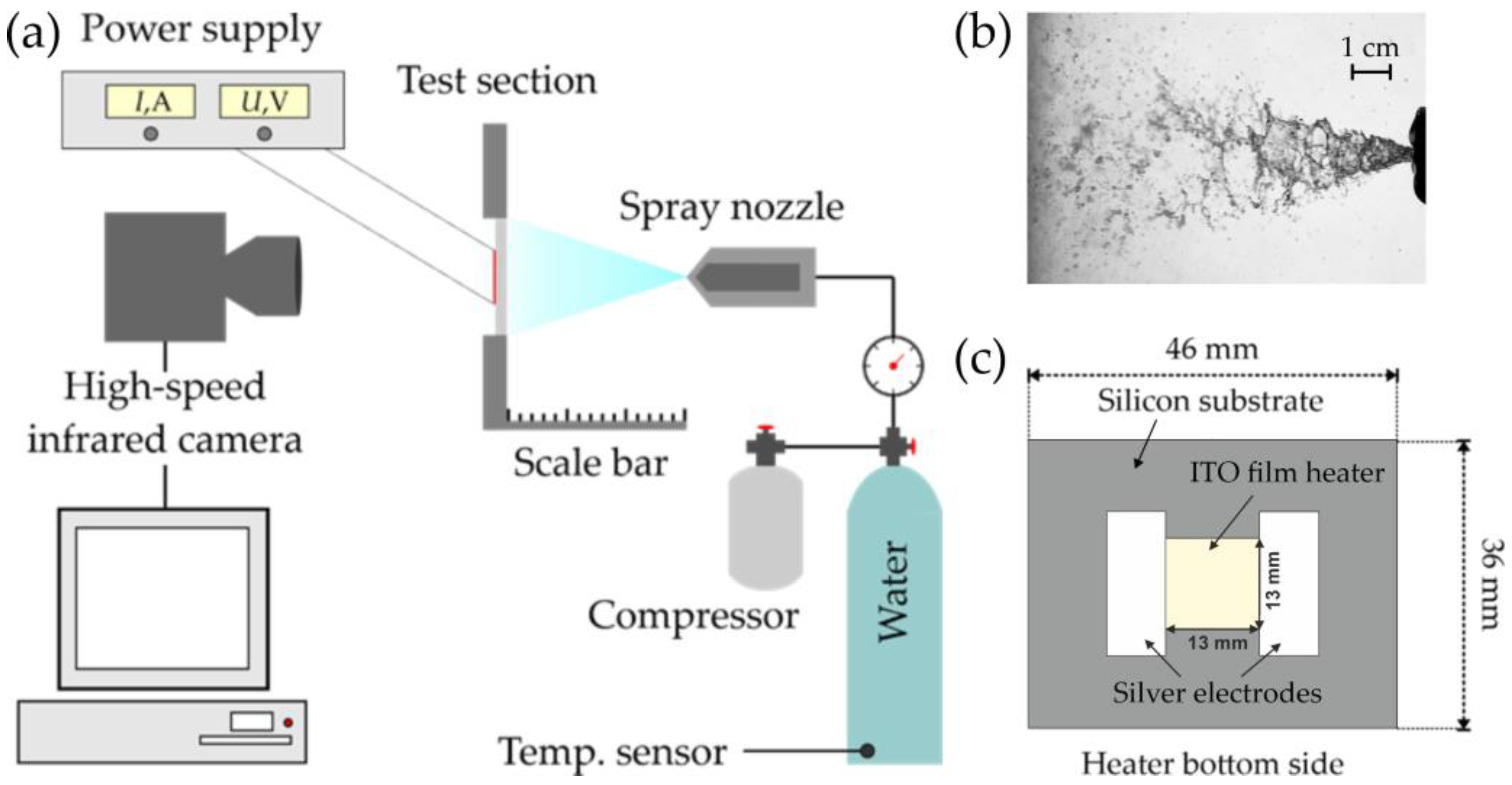
2.1. Experimental Setup and Heater Design

Experiments were performed using the setup presented in Figure 1a. The experimental setup consisted of four basic sections: a circuit to supply liquid, a spray nozzle, an impact surface with a heating system, and a high-speed infrared camera. As the working fluid, distilled water was used at room temperature ( T l 20   ° C ) under atmospheric pressure. A SprayTech DA12.100.M1.YA nozzle made of stainless steel and providing a full cone spray was used in the experiments at three different overpressures of 1.5, 2.5, and 3.5 bar that corresponded to 15.1, 20.3, and 24.2 cm3/s flow rate values. Table 1 presents the other nozzle main characteristics that have been obtained under such conditions using the time-shift method [25] with the SpraySpy tool. The time-shift method relies on the scattering of light by a single particle as it interacts with a shaped light beam. By analysing the combined signal from all scattering orders, it becomes possible to interpret it as a droplet with a specific velocity and size. The SpraySpy tool, in turn, allows for simultaneous measurements of droplet sizes (from 1 μm) and velocities (up to 150 m/s) at a specific point (with a small flow volume measuring 0.5 × 0.5 × 1 mm³). The nozzle was positioned downward, while the SpraySpy was adjusted to the centre of the gas-droplet flow. During the operation of the setup, spray cross-sections were captured along a diametrical line perpendicular to the flow axis, with a 1 mm interval. Figure 1b presents a side view of the spray flow from the nozzle with a 20.3 cm3/s flow rate captured by high-speed visualisation. According to the picture, the spray angle was estimated as approximately 30॰, which coincides with the SpraySpy data.
A flat rectangular substrate made of boron-doped monocrystalline silicon with a thickness of 460 µm with a thin-film ITO (indium tin oxide) heater was used as the heating element (Figure 1c). The surface area of the ITO heater was 13 mm × 13 mm (later referred to as heater size a = 13 mm). Heating was performed by passing a constant electric current (Joule heating) through the silver current-carrying pads, 1 µm thick, deposited on the ITO film surface. The density of the supplied heat flux, q, was determined by the current, I, passing through the ITO film and the potential difference between the silver current-carrying pads, U:
q = I U A
where A is the heater area. The heating sample was mounted into the PEEK flange in the vertical orientation. The spray nozzle was placed straight perpendicular to the heater surface on a slider that made it possible to change the nozzle-to-surface distance.

2.2. IR thermography

To analyse the temperature field of the heater, a high-speed thermographic camera, FLIR X6530sc, with a frame rate of 1.5 kHz and with a 128 × 160 resolution (i.e., ~125 pxl/mm2) was used. Prior to the experiments, the thermographic camera was calibrated using a resistance sensor located near the heater. Since the temperature of the ITO film deposited onto the bottom side of the heating element was recorded, the temperature drop over the substrate thickness was estimated according to the Fourier equation:
T I T O T s   = q δ k S i
where T I T O is the local ITO film temperature directly measured by the IR camera, T s is the retrieved temperature of the impact surface, δ is the silicon substrate thickness, and k S i is the silicon thermal conductivity. Hence, the difference between the temperatures at the front impact side and the back one of the heater increases with an increase in the heat flux density and does not exceed 19.9 °C in the studied range of q up to 6.4 MW/m2. Subsequently, this temperature drop was considered when calculating the heat transfer rate.

2.3. Experimental Procedure

In the initial stage carried out to analyse the influence of the liquid flow rate on the heat transfer characteristics, the nozzle was positioned at a specified distance from the heating surface (L = 25 mm). The control of the liquid flow rate was achieved by changing the excess pressure at the nozzle. Once the desired liquid flow rate was established for spray irrigation, the temperature field of the ITO surface under adiabatic conditions was recorded. Then, using a power source, we increased the thermal load in increments of 0.3–0.4 MW/m2 by current I passing through the thin-film heater. While gradually increasing the heat flux, temperature field measurements were performed under steady-state conditions, where the average surface temperature remained constant over time for each heat flux value. After completing the measurement procedure for a given flow rate, we turned off the power source and set another flow rate at the nozzle, adjusting the level of excess pressure without changing the distance between the nozzle and the impact surface. Then, this procedure was repeated for various liquid flow rates and nozzle-to-surface distances.

2.4. Uncertainty Analysis

The uncertainty in the flow rate is estimated to be 3% for a flow rate range of 15.1–24.2 cm3/s. The ambient room temperature was measured using a platinum detector RTD, the accuracy of which is 0.3%.
The SpraySpy tool allows one to register droplets with a size from 1 μm with 1.7% accuracy and velocity up to 100 m/s with 0.6% accuracy. During the measurement process, comprehensive data in the form of a normal distribution for both the diameter and velocity were obtained based on 1500 or more droplets in less than 10 s. The measurement results are shown in Table 1. To measure the spray angle, flow “edges” were determined by a sharp decrease in the droplet flux density along the cross-section.
The measurement error of the heat flux density q was kept within 4.2% due to the accuracy of the current, voltage, and area measurements. Heat dissipates from the ITO thin-film heater via air convection, radiation, thermal conductivity through the heater edges, and spray cooling. However, the first two mechanisms are negligible because free convection and radiation together give no more than 26 W/m2·K. Losses at the edges are also insufficient due to the small thickness of silicon (460 μm). Side heat flux is less than 6% of the total value considering silicon thermal conductivity, temperature difference through the heater, and edge sizes. Therefore, more than 94% of generated heat is removed via spray cooling. The uniformity of heat generation from the surface of the heater is ensured by its constant thickness. This fact has also been certified in numerous experiments using a similar design of the heating element to study pool boiling on a bare and modified silicon substrate [26,27].
For an accurate measurement of the temperature field of the ITO film surface using the high-speed IR camera, a calibration procedure was carried out before the experiments. The procedure is described in detail in [8]. To ensure the highest level of accuracy and precision of the IR camera during the temperature measurements, the temperature field was averaged over time for each experiment series. Therefore, the total error of the temperature values was less than 3.6% under the mentioned measurement method for the investigated range of parameters. The measurement error of the heat transfer coefficient (HTC) was evaluated as about 7%.

3. Results

New results on local and integral heat transfer characteristics were obtained during the experimental studies on spray cooling for different flow rates and a given initial liquid temperature (20 °C) in the range of heat fluxes from 0 to 6.4 MW/m2. To investigate the effect of the nozzle-to-surface distance on spray cooling performance, experiments were conducted with nozzle-to-surface distances, L, ranging from 7 to 35 mm, covering cases where the impact area of the spray cone was either less or more than that of the heater ( 0.3 < D / a < 1.5 , where D is the spray cone base diameter, and a is the side length of the heater).

3.1. Effect of Liquid Flow Rate

In the first stage, the characteristics of integral heat transfer were studied by varying the flow rate of the liquid and the heat flux density. Figure 2 shows the dependence of the heat flux density on the surface temperature, as well as that of the heat transfer coefficient on the heat flux density, for a given nozzle-to-surface distance of L = 25 mm. The heat transfer coefficient was calculated using the following equation:
H T C = q T s T s 0    
where Ts and Ts0 are the current and initial averaged surface temperature, respectively. A distance of 25 mm was chosen to ensure that the base of the spray cone of the nozzle with a spray angle of 30° fit within the size of the heater. Such a definition was found to be optimal according to the study [21].
In Figure 2a, the heat flux increases almost linearly with an increasing surface temperature, and the slopes of the curves rise with an increasing liquid flow rate. This indicates that an increase in the flow rate leads to an increase in heat transfer intensity and a decrease in the average surface temperature. These conclusions could also be drawn from the analysis of the HTC dependencies presented in Figure 2b, which show that the heat transfer coefficient in the non-boiling regime weakly depends on the heat flux for a given nozzle-to-surface distance in the range of liquid flow rates of 15.1–24.2 cm3/s. A quantitative assessment of the spray cooling efficiency at a distance of 25 mm showed that, while the liquid flow rate increased by 60%, the average HTC increased by only 14%.

3.2. Effect of Nozzle-to-Surface Distance

In the next stage, dependencies of the heat transfer coefficient on the heat flux density were constructed at different distances L for a given liquid flow rate Q of 20.3 cm3/s (Figure 3). In the figure, it can be seen that the heat transfer coefficient weakly depends on the heat flux for all studied nozzle-to-surface distances within the measurement error. However, there is a certain trend of increased heat transfer with an increase in the heat flux, which may be associated with an increase in the heat transfer component related to the evaporation from the free surface of the liquid film formed on the heater during spray irrigation. Moreover, in the investigated modes, we did not observe the nucleate boiling regime, even at heat fluxes up to q = 6.4 MW/m2, which would be characterised by a noticeable increase in the heat transfer rate and a change in the slope of the heat transfer curves [20]. The analysis of the experimental curves also showed that, with a decrease in the distance from 35 to 15 mm, the heat transfer coefficient increases. With the further approach of the nozzle to the surface, the heat transfer intensity slightly decreases, although the curves obtained for distances of 10 and 15 mm lie close enough to each other.
Figure 4 yields the dependence of the heat transfer coefficient on the nozzle-to-surface distance at a given heat flux. As shown, there is a distance at which the maximum heat transfer rate is achieved during spray cooling. For the studied nozzle and heater size, with an increase in the distance up to 15 mm, the HTC slightly increases up to 88 kW/m2·K, and with an increase in the distance beyond 15 mm, there is a sharp HTC decline (by up to 1.8 times at a distance of 35 mm). Thus, it can be concluded that there is a certain nozzle-to-surface distance at which the maximum intensity of heat transfer in non-boiling mode is observed. The point of inflection of the HTC(L) dependence can be considered one of the criteria for choosing the optimal distance.
To further investigate the effect of the nozzle-to-surface distance on spray cooling efficiency, a detailed analysis of the temperature fields of the heater was conducted. The IR visualisation frames presented in Figure 5 vividly demonstrate how much the nozzle-to-surface distance L affects the nature and degree of non-uniformity of the temperature field and the local intensity of heat transfer over the heater surface. For example, for L ≥ 20 mm, the highest temperature is observed in the central area, decreasing towards the periphery. At distances of L ≤ 15 mm, a different pattern is observed: an area with a minimum temperature appears in the form of a “ring” on the thermograms, the radius of which decreases as the distance decreases from 15 to 7 mm.
Figure 6 show the surface temperature profiles along the diagonal (x-axis in Figure 5) at different distances from the nozzle for a given liquid flow rate of q = 20.3 cm3/s and a heat flux density of q = 4 MW/m2. In the graphs, it can be seen that the temperature in the centre of the heater noticeably decreases with a decreasing distance from 102.9 °C at 30 mm to 60.5 °C at 7 mm, i.e., a decline of approximately 41.2%. Moreover, the presented data show that, with a decrease in the distance, the shape of the temperature profile changes. If for distances of L ≥ 25 mm the temperature profile has an “arc” shape with a decrease in temperature from the centre to the periphery, then, for distances of L ≤ 20 mm, the profile has a W-like shape with alternating extrema. This suggests that the droplet impact pattern for the used pressure nozzle is a quasi-full cone with a clearly defined maximum liquid flow rate at the periphery of the spray cone. In fact, this irrigation pattern is typical for most single-phase nozzles at relatively short distances [2,22,28]. Moreover, it can be seen in the graphs presented in Figure 6 that, with a decrease in the distance from 15 mm to 7 mm, the temperature in the peripheral area increases, which leads to an increase in the degree of non-uniformity of the temperature profile. Thus, the temperature difference between the central and peripheral regions at a distance of L = 7 mm with a heat flux density of q = 4 MW/m2 can reach 18 °C, while the temperature difference at a distance of L = 15 mm does not exceed 7 °C.
The experimental results show that the temperature field in the non-boiling regime is quite uniform at large distances. However, with an increase in distance, the maximum surface temperature also increases significantly, which has an adverse effect on the overall heat transfer. Conversely, reducing the distance between the nozzle and the surface leads to a decrease in the integral temperature. However, it was observed that there is a considerable increase in the degree of non-uniformity at nozzle-to-surface distances less than 15 mm.
Due to the significant non-uniformity of the temperature field on the surface during spray cooling, the criterion for selecting the optimal distance should also consider the degree of this non-uniformity. In particular, Xia et al. [24] proposed using the parameter of cooling non-uniformity (CNU) to choose the optimal distance. CNU is defined as the average ratio of the difference between the local and average surface temperatures over the wall overheating:
C N U = 1 N | T l o c T s | T s T l
where N is the total number of temperature measurements; Tloc and Ts are the local and average surface temperatures, respectively; and Tl is the liquid inlet temperature. CNU varies in the range 0 ≤ CNU < 1, and the lower this parameter, the more uniform the surface temperature. Thus, for a cooled surface with an absolutely uniform surface temperature, CNU = 0. However, a CNU close to 1 deals with deviations from the average surface temperature of the same order of magnitude. By taking this parameter into account, it is possible to evaluate the degree of non-uniformity of the temperature field and determine the optimal nozzle-to-surface distance for efficient spray cooling.
Figure 7a,b show the dependence of the heat transfer coefficient during spray cooling and the CNU parameter on the nozzle-to-surface distance for heat flux q = 4 MW/m2. Comparing these two graphs, one can observe that the point of the maximum heat transfer coefficient corresponds to the minimum value of the CNU parameter, which indicates that the degree of non-uniformity is the lowest at 15 mm. Therefore, based on the analysis of these curves, it can be concluded that a distance of 15 mm is the optimal for spray cooling efficiency for the given nozzle, heater size, and flow rate. As observed, the CNU parameter can be successfully used to analyse the degree of non-uniformity of the temperature field and as a criterion for selecting the optimal nozzle-to-surface distance. However, the CNU graph does not completely replicate the behaviour of the heat transfer coefficient curve with a changing distance. An analysis shows that, at a distance of L = 35 mm, CNU = 0.173, which is noticeably lower than that at distances of 25–30 mm. This is due to the spray cone base diameter being larger than the heater size and the liquid flow within the spray cone being more homogeneous; this leads to a more uniform temperature distribution across the heater area and a more uniform heat transfer coefficient, which results in a decrease in CNU. However, it does not necessarily mean that the heat transfer rate is higher in this case. On the contrary, as seen in Figure 7a, the minimum value of the heat transfer coefficient is observed at L = 35 mm. Therefore, it is essential to consider both the CNU parameter and the heat transfer coefficient curve to select the optimal nozzle-to-surface distance for efficient spray cooling.
Another criterion that can be used to determine the optimal distance for pressure nozzles is based on a measurement of the maximum surface temperature. Figure 7c shows the dependence of the maximum surface temperature of the heater for a heat flux of 5 MW/m2 depending on the distance L. The graph shows that the optimal distance of L = 15 mm corresponds to the minimum value of the maximum surface temperature, as well as the CNU parameter. Unlike CNU, the Tmax value at L = 15 mm is the only minimum on the graph, and the behaviour of the curve reflects that of the heat transfer coefficient curve. Hence, the task of selecting the optimal distance for spray cooling can be simplified to finding the lowest possible value for the highest surface temperature of the heater. In our opinion, using this criterion to determine the optimal distance has some advantages in real experimental conditions, especially with the availability of tools such as an IR camera, as it allows for a real-time determination of the maximum surface temperature of the heater without additional calculations. Furthermore, examining the maximum temperature enables us to assess our proximity to the critical temperature associated with the occurrence of crisis phenomena.
While the distance when the spray fully covers the heated area equals 25 mm comes from a pure geometry task, our results show that the optimal distance is 15 mm. Thus, we suppose the usage of the equation in [21] with a correction factor K less than 1. In this way, the optimal distance can be determined as the following:
L o p t = K a 2 c t g ( α 2 )
where a is the side length of the heater, α is the spray angle, and K is the correction factor. For our case, K equals 0.6. When K = 1, the formula repeats the relationship [21] for the distance at which the base of the spray cone is accurately inscribed in the square of the heater. Notably, the ratio (5) with K = 0.6 requires further verification using other types of nozzles with different spray cone angles, an extended range of spray parameters, and various fluids, as well as heaters of different sizes. In fact, as can be seen in Equation (5), with an increase in the size of the heat-generated region, the optimal distance should increase for the same nozzle. However, with an increase in the distance, as shown by the visualisation of the spray flow, the spray also evolves, which can certainly have some influence on the coefficient K.

4. Conclusions

This work is devoted to the study of the spray cooling performance of a heated silicon substrate with an ITO thin-film heater. Experiments were carried out using a spray nozzle with different liquid flow rates (15.1–24.2 cm3/s) with a nozzle-to-surface distance in the range of 7–35 mm and heat fluxes up to 6.4 MW/m2. The main results are the following:
  • The increase in the liquid flow rate in the studied range led to a slight increase in cooling performance in the non-boiling mode. Thus, increasing the flow rate by 60% only increased the heat transfer coefficient by 14%.
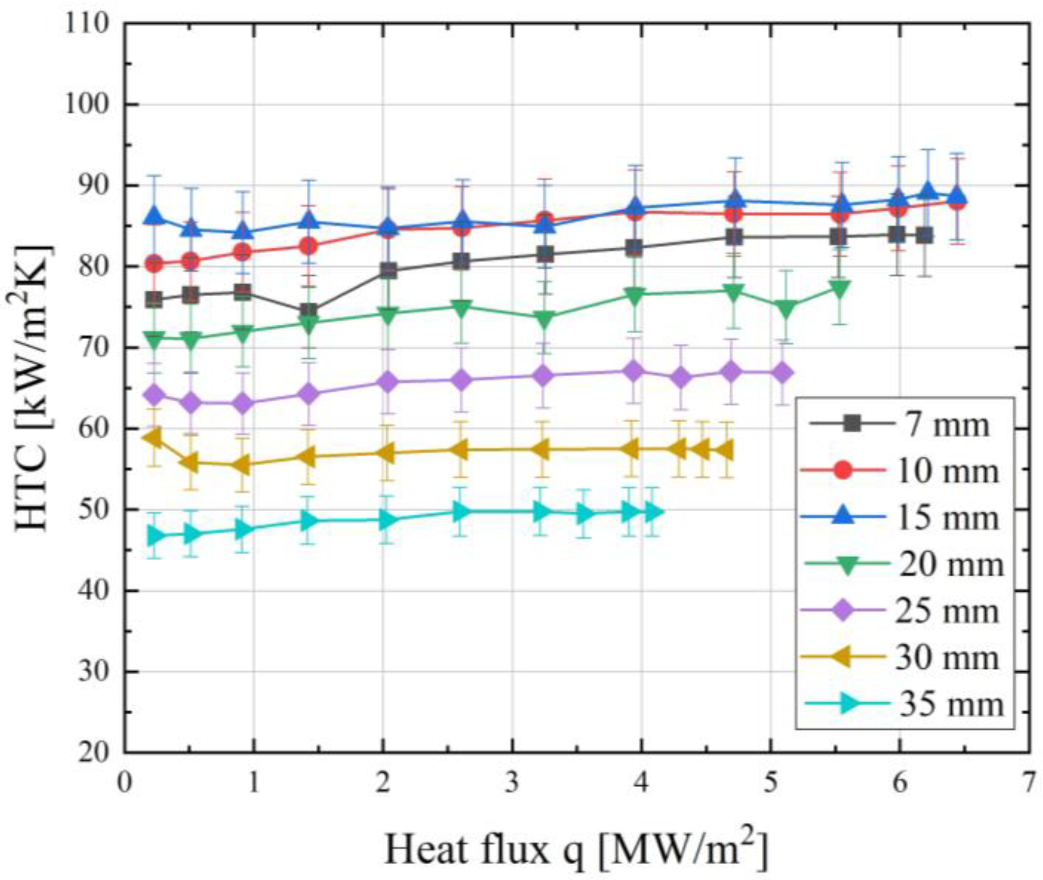
  • The experimental results demonstrate that the heat transfer coefficient exhibited a weak dependence on the heat flux in non-boiling mode but tended to increase as the heat flux increased within the measurement error.
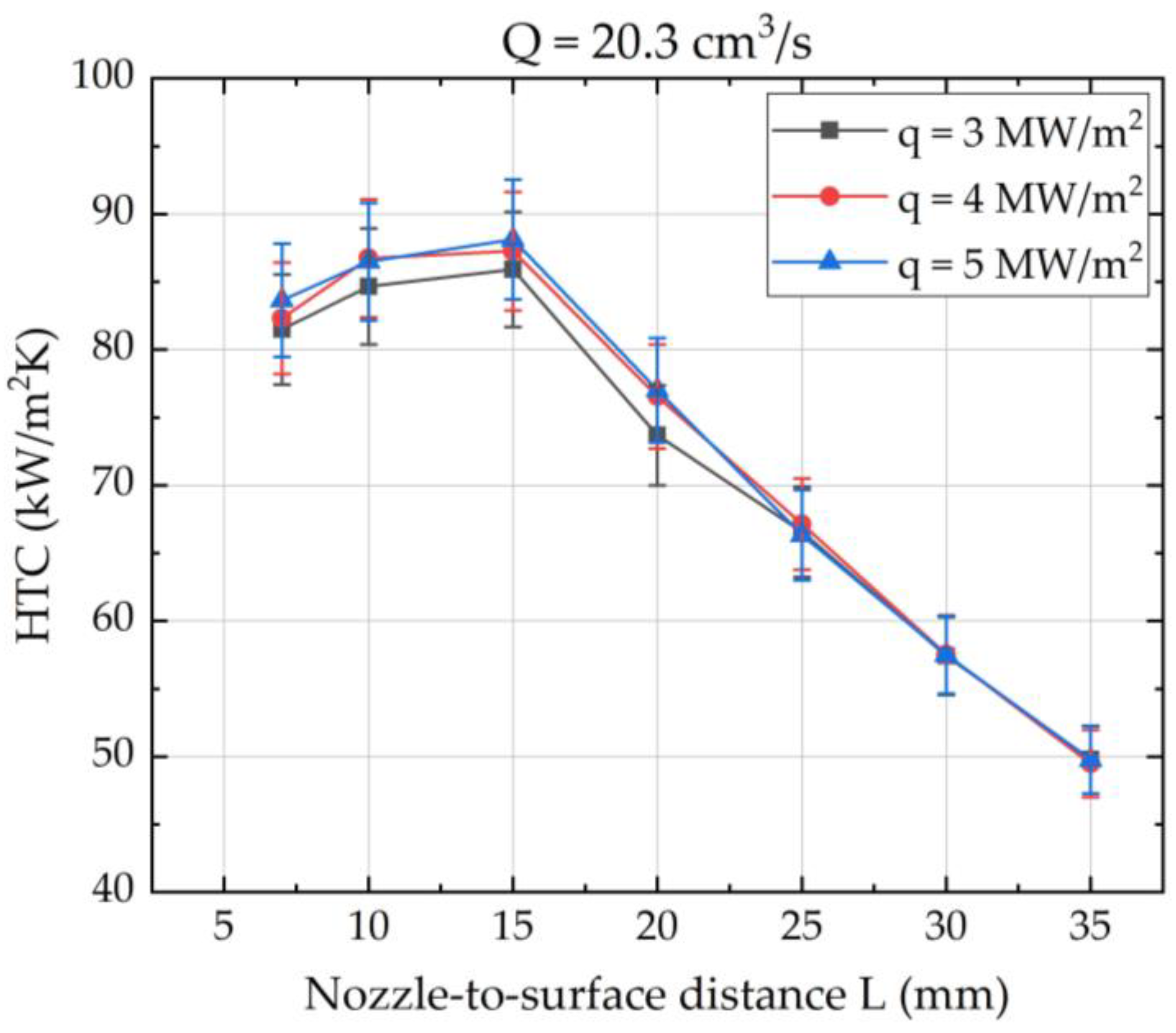
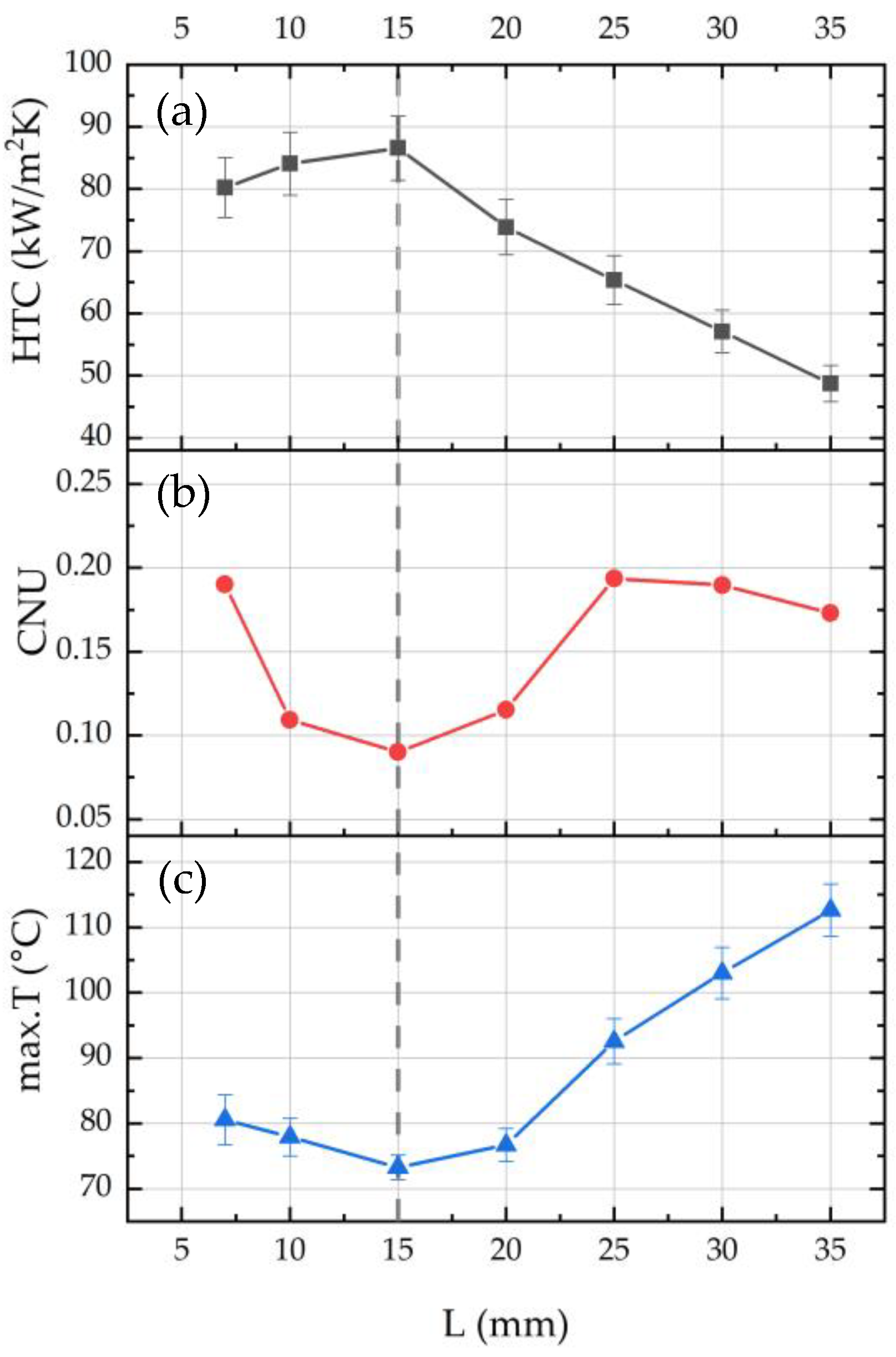
  • Spray cooling performance strongly depends on the distance from the nozzle to the surface in non-boiling mode. It was shown that there was an optimal distance at which the maximum heat transfer rate is achieved during spray cooling. Moreover, the heat transfer rate could change by more than 44% for the investigated nozzle when changing D / a from 0.3 to 1.5, where D is the spray cone base diameter, and a is the side length of the heater.
  • For the studied parameters, including the heater size, the optimal distance providing the best heat transfer performance was determined and equalled 15 mm for the investigated nozzle, which is less than the distance at which the spray cone completely covers the heater. It is suggested to use Equation (5) with the correction factor K = 0.6 for determining the optimal nozzle-to-surface distance for a heat exchange surface of similar sizes.
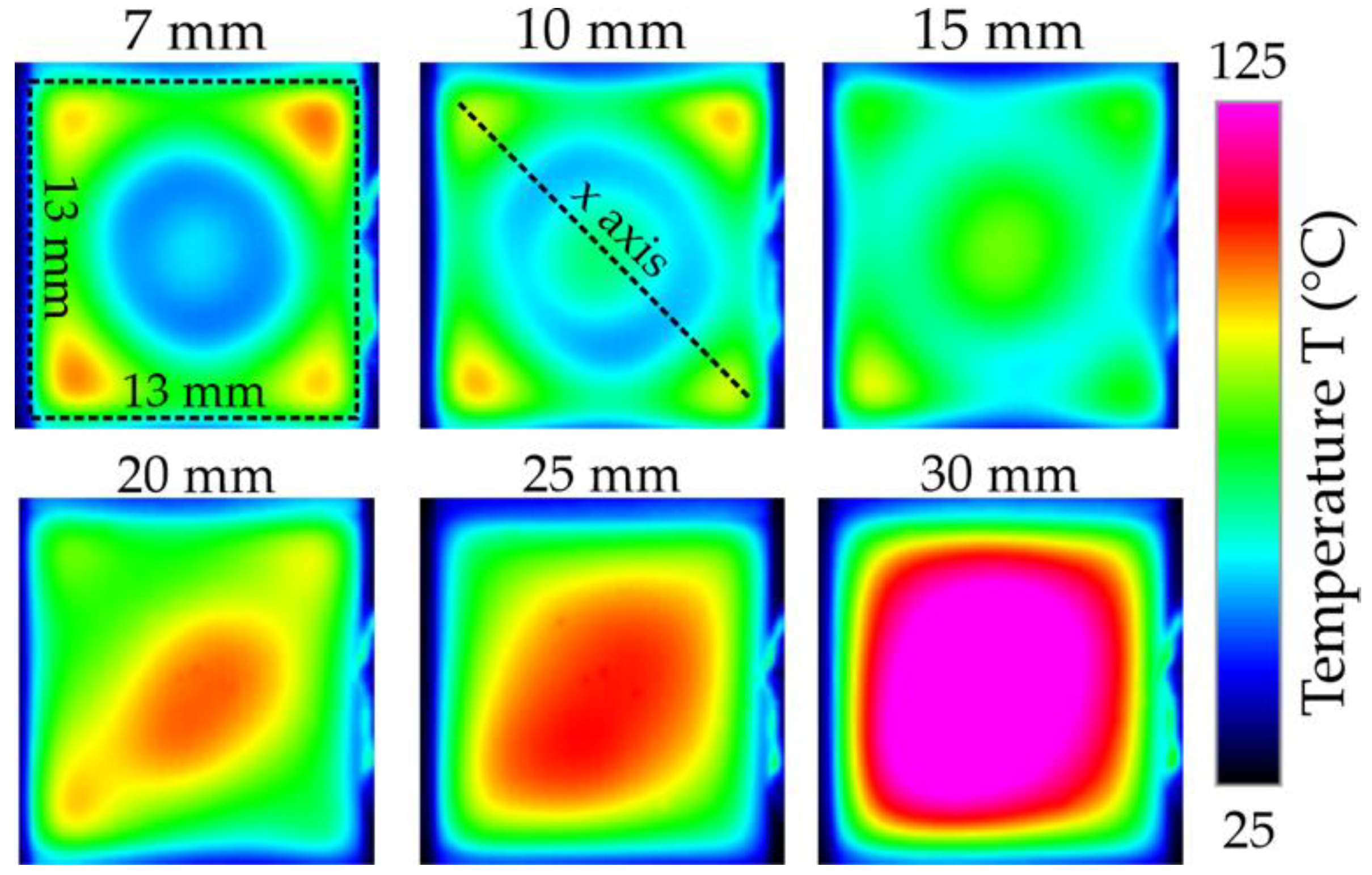
  • The nozzle-to-surface distance significantly affects the local temperature distribution. The degree of temperature non-uniformity was evaluated using the cooling non-uniformity (CNU) parameter, which reached its minimum value at 15 mm. As an alternative method for determining the optimal position, it is proposed to analyse the measurements of the maximum temperature of the surface. The distance at which the minimum value of the maximum local temperature is observed is optimal for achieving maximum heat transfer.
Undoubtedly, some of the conclusions made in the study require further verification. However, in our view, the analysis carried out in this research will already allow future researchers to better navigate the issue of nozzle positioning in spray cooling systems.

Author Contributions

Conceptualization, A.S.; Methodology, N.M. and V.S.; Software, I.V.; Investigation, I.V. and N.M.; Resources, A.N.; Data curation, I.V.; Writing—original draft, I.V.; Writing—review & editing, A.S. and V.S.; Visualization, A.N.; Supervision, A.S.; Project administration, A.S.; Funding acquisition, A.S. All authors have read and agreed to the published version of the manuscript.

Funding

This work was supported by the Russian Science Foundation (Grant No. 22-19-00581).

Institutional Review Board Statement

Not applicable.

Informed Consent Statement

Not applicable.

Data Availability Statement

Not applicable.

Conflicts of Interest

The authors declare no conflict of interest.

References

  1. Liang, G.; Mudawar, I. Review of Spray Cooling—Part 1: Single-Phase and Nucleate Boiling Regimes, and Critical Heat Flux. Int. J. Heat Mass Transf. 2017, 115, 1174–1205. [Google Scholar] [CrossRef]
  2. Gao, X.; Li, R. Spray Impingement Cooling: The State of the Art. In Advanced Cooling Technologies and Applications; Murshed, S.M.S., Ed.; IntechOpen: Rijeka, Croatia, 2019. [Google Scholar]
  3. Khandekar, S.; Sahu, G.; Muralidhar, K.; Gatapova, E.Y.; Kabov, O.A.; Hu, R.; Luo, X.; Zhao, L. Cooling of High-Power LEDs by Liquid Sprays: Challenges and Prospects. Appl. Therm. Eng. 2021, 184, 115640. [Google Scholar] [CrossRef]
  4. Yoshida, K.; Abe, Y.; Oka, T.; Mori, Y.H.; Nagashima, A. Spray Cooling under Reduced Gravity Condition. J. Heat Transfer. 2001, 123, 309–318. [Google Scholar] [CrossRef]
  5. Zhao, X.; Zhang, H.; Zhang, B.; Yang, Z.; Ma, X. Experimental Investigation of the Mechanism of Isolated Liquid Film Flow in Spray Cooling. Int. J. Heat Mass Transf. 2022, 192, 122904. [Google Scholar] [CrossRef]
  6. Rini, D.P.; Chen, R.H.; Chow, L.C. Bubble Behavior and Nucleate Boiling Heat Transfer in Saturated FC-72 Spray Cooling. J. Heat Transfer. 2002, 124, 63–72. [Google Scholar] [CrossRef]
  7. Griffin, A.R.; Vijayakumar, A.; Chen, R.-H.; Sundaram, K.B.; Chow, L.C. Development of a Transparent Heater to Measure Surface Temperature Fluctuations under Spray Cooling Conditions. J. Heat Transfer. 2008, 130, 114501. [Google Scholar] [CrossRef]
  8. Serdyukov, V.; Miskiv, N.; Surtaev, A. The Simultaneous Analysis of Droplets’ Impacts and Heat Transfer during Water Spray Cooling Using a Transparent Heater. Water 2021, 13, 2730. [Google Scholar] [CrossRef]
  9. Mudawar, I.; Valentine, W.S. Determination of the Local Quench Curve for Spray-Cooled Metallic Surfaces. J. Heat Treat. 1989, 7, 107–121. [Google Scholar] [CrossRef]
  10. Rybicki, J.R.; Mudawar, I. Single-Phase and Two-Phase Cooling Characteristics of Upward-Facing and Downward-Facing Sprays. Int. J. Heat Mass Transf. 2006, 49, 5–16. [Google Scholar] [CrossRef]
  11. Gao, X.; Kong, L.; Li, R.; Han, J. Heat Transfer of Single Drop Impact on a Film Flow Cooling a Hot Surface. Int. J. Heat Mass Transf. 2017, 108, 1068–1077. [Google Scholar] [CrossRef]
  12. Hou, Y.; Jie, P.; Wang, H. Heat Transfer Mechanisms of Single Droplet Impacting onto Flowing Film. Int. J. Heat Mass Transf. 2019, 132, 952–960. [Google Scholar] [CrossRef]
  13. Park, C.; Seol, J.; Aldalbahi, A.; Rahaman, M.; Yarin, A.L.; Yoon, S.S. Drop Impact Phenomena and Spray Cooling on Hot Nanotextured Surfaces of Various Architectures and Dynamic Wettability. Phys. Fluids 2023, 35, 027126. [Google Scholar] [CrossRef]
  14. Soriano, G.E.; Zhang, T.; Alvarado, J.L. Study of the Effects of Single and Multiple Periodic Droplet Impingements on Liquid Film Heat Transfer. Int. J. Heat Mass Transf. 2014, 77, 449–463. [Google Scholar] [CrossRef]
  15. Qiu, L.; Dubey, S.; Choo, F.H.; Duan, F. Splashing of High Speed Droplet Train Impinging on a Hot Surface. Appl. Phys. Lett. 2015, 107, 164102. [Google Scholar] [CrossRef]
  16. Qiu, L.; Dubey, S.; Hoong Choo, F.; Duan, F. The Statistical Analysis of Droplet Train Splashing after Impinging on a Superheated Surface. J. Heat Transfer. 2017, 139, 052201. [Google Scholar] [CrossRef]
  17. Zhang, T.; Alvarado, J.L.; Muthusamy, J.P.; Kanjirakat, A.; Sadr, R. Heat Transfer Characteristics of Double, Triple and Hexagonally-Arranged Droplet Train Impingement Arrays. Int. J. Heat Mass Transf. 2017, 110, 562–575. [Google Scholar] [CrossRef]
  18. Liang, G.; Mudawar, I. Review of Mass and Momentum Interactions during Drop Impact on a Liquid Film. Int. J. Heat Mass Transf. 2016, 101, 577–599. [Google Scholar] [CrossRef]
  19. Gao, X.; Li, R. Local Heat Transfer of Spray Cooling on a Thin Film Heater. In Proceedings of the 8th International Symposium on Multiphase Flow, Heat & Mass Transfer and Energy Conversion, Chengdu, China, 17–19 December 2016. [Google Scholar]
  20. Xiang, L.; Yu, X.; Hong, T.; Yang, X.; Xie, B.; Hu, R.; Luo, X. Performance of Spray Cooling with Vertical Surface Orientation: An Experimental Investigation. Appl. Therm. Eng. 2023, 219, 119434. [Google Scholar] [CrossRef]
  21. Mudawar, I.; Estes, K.A. Optimizing and Predicting CHF in Spray Cooling of a Square Surface. J. Heat Transfer. 1996, 118, 672–679. [Google Scholar] [CrossRef]
  22. Gao, X.; Li, R. Effects of Nozzle Positioning on Single-Phase Spray Cooling. Int. J. Heat Mass Transf. 2017, 115, 1247–1257. [Google Scholar] [CrossRef]
  23. Wang, J.-X.; Li, Y.-Z.; Zhang, H.-S.; Wang, S.-N.; Mao, Y.-F.; Zhang, Y.-N.; Liang, Y.-H. Investigation of a Spray Cooling System with Two Nozzles for Space Application. Appl. Therm. Eng. 2015, 89, 115–124. [Google Scholar] [CrossRef]
  24. Xia, Y.; Gao, X.; Li, R. Management of Surface Cooling Non-Uniformity in Spray Cooling. Appl. Therm. Eng. 2020, 180, 115819. [Google Scholar] [CrossRef]
  25. Schäfer, W.; Tropea, C. Time-Shift Technique for Simultaneous Measurement of Size, Velocity, and Relative Refractive Index of Transparent Droplets or Particles in a Flow. Appl. Opt. 2014, 53, 588. [Google Scholar] [CrossRef] [PubMed]
  26. Serdyukov, V.; Starinskiy, S.; Malakhov, I.; Safonov, A.; Surtaev, A. Laser Texturing of Silicon Surface to Enhance Nucleate Pool Boiling Heat Transfer. Appl. Therm. Eng. 2021, 194, 117102. [Google Scholar] [CrossRef]
  27. Serdyukov, V.; Vladyko, I.; Starinskiy, S.; Rodionov, A.; Shukhov, Y.; Malakhov, I.; Safonov, A.; Surtaev, A. Pool Boiling Performance on the Textured Hemi-Wicking Surfaces Fabricated by Nanosecond Laser Ablation. Appl. Therm. Eng. 2023, 228, 120472. [Google Scholar] [CrossRef]
  28. Zhifu, Z.; Weitao, W.; Bin, C.; Guoxiang, W.; Liejin, G. An Experimental Study on the Spray and Thermal Characteristics of R134a Two-Phase Flashing Spray. Int. J. Heat Mass Transf. 2012, 55, 4460–4468. [Google Scholar] [CrossRef]
Figure 1. (a) The scheme of experimental setup, (b) HSV frame of spray flow, (c) heating element based on silicon substrate with thin-film indium tin oxide (ITO) heater.
Fluids 08 00191 g001
Figure 2. The dependencies of heat flux on the impact surface temperature (a) and heat transfer coefficient on heat flux (b) at spray cooling for different flow rates at certain nozzle-to-surface distance (L = 25 mm).
Fluids 08 00191 g002
Figure 3. Heat transfer coefficient vs. heat flux for different distance between spray nozzle and impact surface at given flow rate (q = 20.3 cm3/s).
Fluids 08 00191 g003
Figure 4. The dependence of the heat transfer coefficient (HTC) on the nozzle-to-surface distance at given heat fluxes.
Fluids 08 00191 g004
Figure 5. The time-averaged IR thermography frames of the heating surface for different nozzle-to-surface distances at given flow rate (q = 20.3 cm3/s) and heat flux density (q = 5 MW/m2).
Fluids 08 00191 g005
Figure 6. (a) The temperature profiles of the heat exchange surface depend on the nozzle-to-surface distance at given flow rate (20.3 cm3/s) and heat flux (4 MW/m2). (b) Side view of spray cone at given flow rate (20.3 cm3/s).
Fluids 08 00191 g006
Figure 7. The dependencies of heat transfer coefficient (a), cooling non-uniformity (CNU) (b), and maximum local temperature (c) on distance between nozzle and impact surface.
Fluids 08 00191 g007
Table 1. Spray characteristics of pressure nozzle SprayTech DA12.100.M1.YA.
Overpressure P (Bar)Liquid Flow Rate Q (cm3/s)Sauter Mean Diameter d32 (µm)Mean Velocity vm (m/s)Spray Angle α (°)
1.515.12016.427.7
2.520.31538.728.4
3.524.214610.630.1
Disclaimer/Publisher’s Note: The statements, opinions and data contained in all publications are solely those of the individual author(s) and contributor(s) and not of MDPI and/or the editor(s). MDPI and/or the editor(s) disclaim responsibility for any injury to people or property resulting from any ideas, methods, instructions or products referred to in the content.

