Abstract
This study investigates the gas dynamic effects and atomization behavior of a novel sonic bluff body-assisted two-fluid atomizer with three different geometric configurations based on airflow orifice diameters (d) of 2.0 mm, 3.0 mm, and 4.0 mm. Along with a 280 µm annular liquid sheet, atomizers that employed a central bluff body (cone) with 6.0 mm cone distance (Lc) are compared based on the range of different air and liquid (water) flow rates. The spray-bluff body-impacted secondary atomization was characterized through volume-normalized droplet size distribution (DSD) and cumulative droplet distribution, excentricity plots, Sauter mean diameter (SMD), and relative span factor (Δ). Droplet number density decreases with the increase in radial location, with lesser droplet density for the 3.0 mm atomizer. DSD and cumulative droplet distribution become less uniform with the increase in the radial locations with wider distribution for larger diameter atomizers (4.0 mm). Droplet excentricity follows an inverse relationship with the droplet diameter such that high diameter droplets have low excentricity (%) and vice versa. SMD and relative span factor (RSF) showed opposite trends when plotted (line plots) against the air-to-liquid ratio (ALR) with larger fluctuation in the SMD than the RSF (Δ) value. The spray pattern spread increases gradually with increasing liquid loading and with decreases in the ALR value for all atomizers.
1. Introduction
Sprays are widely studied in industrial applications, from spray drying in the food processing industry to fuel spray combustors in industrial diesel engines, from fire suppression to the metal powder industry (Nasr [1]). The spray comprises the primary atomization (liquid sheet disintegration) and the secondary atomization (droplet dynamics). The sonic prefilming atomizer for 2D sheet atomization was first employed in Kihm et al. [2]. Though the Sauter mean diameter (SMD) value decreases after the advent of shock waves, it still leads to probing supersonic atomization. The principle of the sonic prefilming atomizer is that the shock waves interact with the sheet/film, fragmenting it into a multitude of ligaments through energy exchange owing to the highly intense shearing effect, thus producing a very fine ensemble of droplets. The shock wave strength can be used for shattering the liquid sheet through shock energy absorption, resulting in many fragments/ligaments, and later, fine mist formation (Adiga et al. [3]) due to the sudden change in properties/discontinuities (Chauvin et al. [4]). The mist region (discussed above) is denoted by fine daughter droplets formed from the parent drops at very high relative velocities (Borisov et al. [5]). Issac et al. [6] obtained very fine droplets due to the boundary layer stripping of the liquid jet owing to the high shearing effect of the Mach 1.5 airflow. Though jet configuration was studied earlier, the twin-fluid atomizer incorporating the sheet is better for achieving finer atomization than the liquid jet (Balaji et al. [7]), with more efficient atomization in the thin sheet configuration (Leboucher et al. [8]). A sheet with inner air configuration effectively produces finer sprays and smaller drop size distribution (Fu et al. [9]), also proved theoretically (Lee et al. [10]), though without any supplementary mechanical atomization mechanism (like in our study). The longer narrow supersonic air jet proved to give finer atomization in both converging–diverging (CD) and convergent atomizers (Mates et al. [11,12]) with uniform drop size distribution (DSD) in the CD configuration owing to the comparatively higher atomization efficiency (Fritsching et al. [13]).
Numerous factors characterize the multi-scale sprays: SMD, drop size distribution (DSD), spray distribution pattern, etc. DSD is shaped by the air–liquid interaction in the secondary atomization zone. The increment of GLR (gas to liquid ratio) narrows the DSD (Kulkarni et al. [14]). The spray drop size distribution affects evaporation and burning characteristics; however, ignition and combustion characteristics depend on other factors such as combustor systems, boiler designs, etc. The DSD is crucial for estimating incomplete combustion as it may lead to NOx, particulate matter, etc. (Lefebvre [15]). The uniformity of the liquid fuel distribution aids in obtaining low NOx and CO emissions (Lovett et al. [16]). Narrower drop size distribution provided complete combustion when SMD held constant, as mentioned in Bossard et al. [17]. The SMD and DSD depend on the type of atomizers such that different atomizer designs give varying drop sizes at different spatial locations. Drop size generally increases from the spray centerline to the spray periphery with an annular sheet atomizer (Li et al. [18]) (Leboucher et al. [19]) with strong liquid flow rate dependence on the SMD with an annular sheet arrangement (Choi et al. [20]).
Studies related to aero-mechanical atomizers are scarce. One such central bluff body design is mentioned in Gullberg et al. [21] which acts as a prefilmer and wall. The atomizer with a compound airflow mechanism or bluff body insertion adds further complexity. The application of mechanical breakup (solid body attachment) in addition to the aerodynamic breakup provides complex but nonetheless better atomization. Note that secondary atomization has a different meaning in bluff body-based flow dynamics than the conventional notion (breakup of primary atomized droplets into secondary droplets through aerodynamic interaction). Fragmented ligaments/globules impacting on a rigid solid surface (bluff body) lead to a whole range of phenomena, stretching from splashing to corona formation (Roisman [22]), (Yarin [23]), which affects the spray drop size and shape and drop size distribution. The gas-cushioning effect also contributes to the corona splash by lifting the lamella away from the solid (Josserand [24]). The enhanced compressibility effect at higher velocities (~30 m/s) results in additional energy exchange between the ruptured liquid sheet and high-speed air, as mentioned in Yarin [25].
Due to bluff body impact, the droplet number density and mean drop size are also unevenly altered at various spatial locations within the spray (Bachalo et al. [26]). However, the airflow–droplet interaction segregates the droplet sizes into two distinct regions such that smaller droplets follow the low-velocity recirculation region; larger droplets with higher inertia follow the spray cone trajectory (Rudoff et al. [27]). Carrier et al. [28] observed that a smaller quantity of droplets entrained into the low-velocity recirculation region results in higher pollutants and lower combustion efficiency. However, the bluff body provides flame stability through good air–liquid mixing due to the recirculation region (wake flow) mentioned in Eckelmann et al. [29].
The ensemble of newly formed droplets interacts with the airflow field, inducing a specific spray pattern downstream. The intermittency in the air velocity gives rise to spray fluctuations (Batarseh et al. [30]), affecting the spatio-temporal spray pattern uniformity. The spray distribution pattern complements the SMD and DSD in assessing the spray characteristics. Spray distribution patterns can be measured using the patternation technique. There are two types of patternation techniques: mechanical and optical patternation (Sivathanu et al. [31]). Optical patternation (phase Doppler particle analyzer (PDPA), Mie scattering technique) has limitations due to multiple scattering and signal extinction, while techniques based on one-photon fluorescence described in (Roth et al. [32]) can be used especially in large-scale sprays. Mechanical patternation is a good alternative for semi-industrial scale sprays and is performed with a ‘Patternator’. It can be a circular sector, a linear inline, and a concentric ring shape (employed here) (Tate et al. [33]). For large-scale, multi-nozzle sprays, patternation serves as a mass flux measurement technique (Jain et al. [34]) which can be utilized in studies such as fire suppression (Jordan et al. [35]) and fire-accident mitigation (Shrigondekar et al. [36]). Patternation measurements can also characterize combustion non-ideality as initial spray distribution influences combustor performance (Cohen et al. [37]).
This work explores the spray characteristics for the bluff body atomizers dissimilar in airflow jet diameters rather than variation based on cone distance (Sikka et al. [38]). The novelty of the atomizer lies in the fact that liquid sheet–shock interaction followed by bluff body-induced reflected shock imparts energy which led to an ensemble of ligaments and smaller droplets. Near-nozzle spray bluff body dynamics were visualized to study the spray formation. The SMD and DSD were obtained using the laser-based shadowgraphy technique. A novel ring-shaped 120° sector Patternator (in house) was utilized for measuring the spray distribution pattern (spray uniformity). It was hypothesized that complex gas–liquid interactions and blunt body impacts would result in different spray disintegration behaviors in different atomizer configurations. Padwal et al. [39] observed that drop diameter is directly related to the diameter of the airflow jets. The de Laval nozzle geometry (in terms of diameter) also affects the mean drop size and drop size distribution, especially at low GLR values (Chen et al. [40]). This work analyzed different air-jet diameter atomizers to optimize the airflow rate based on the ALR. Reducing the air pressure or amount of atomizing air to achieve fine spray is an important constraint in industrial applications.
2. Materials and Methods
The detailed experimental study employed different bluff body atomizers with distinct air-orifice jet diameters (d) (2.0 mm, 3.0 mm, and 4.0 mm), with an annular liquid sheet of 280 µm thickness, as shown in Figure 1. The fixed cone distance (6.0 mm) was employed in all three atomizer configurations.
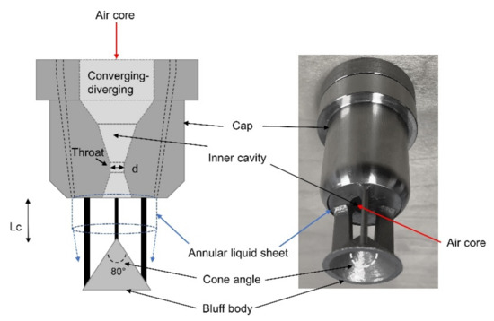
Figure 1.
Schematic of atomizer design (in (left)) and atomizer (in (right)).
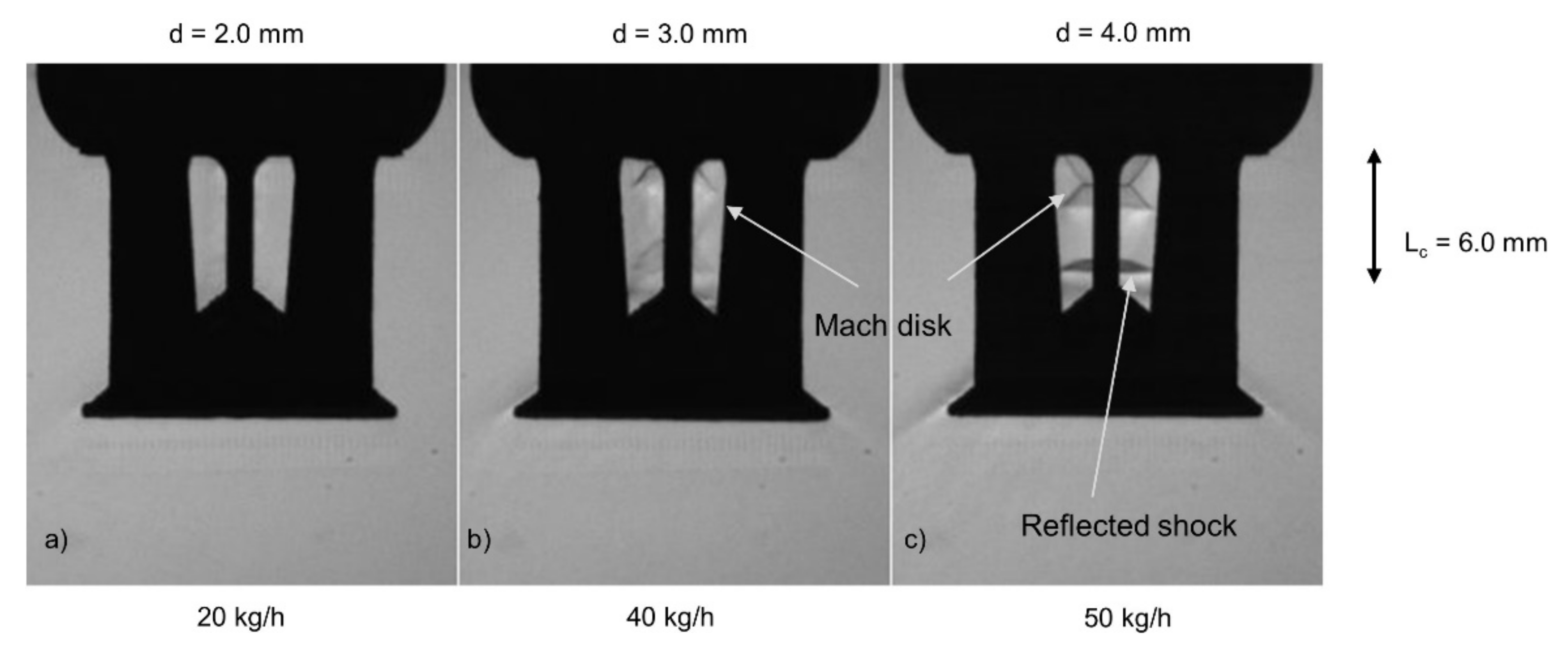
The airflow was visualized using the Shadowgraph system using an Optoelectronics 3.0 W red LED light. Using a high-speed Photron SA-Z camera, which is based on a complementary metal-oxide semiconductor (CMOS); imaging was performed at 21,000 frames per second with a shutter speed of approximately 50 μs. The whole flow process is explained in detail (Sikka et al. [41]) for the atomizers without bluff body attachment. The oblique shock waves followed by the Mach disk and the Prandtl–Meyer expansion waves are depicted in the airflow patterns (Figure 2). The bluff body-induced reflected shock is more prominently visible in the 4.0 mm atomizer configuration due to the high Mach number value of 1.59 (as compared to Mdesign = 1.85) owing to the small nozzle exit-to-throat area ratio (A/A*) value of 1.5, where A* is throat area. The pressure–Mach number (P-M) relation depicts the (given by Equation (1)) design Mach number (Mdesign) and corresponding Pressure (P0) (based on area ratio A/A*) assuming isentropic flow field throughout the flow-field (Liepmann & Roshko [42]); this is depicted in Table 1:
where P (=1 bar (g)) is ambient pressure; γ (=1.4) is the ratio of specific heat.

Figure 2.
Airflow pattern for various airflow rates at (a) 2.0 mm (b) 3.0 mm and (c) 4.0 mm air-orifice diameter atomizers.

Table 1.
Conditions for operational Mach number (M) and pressure (Pt) ranges.
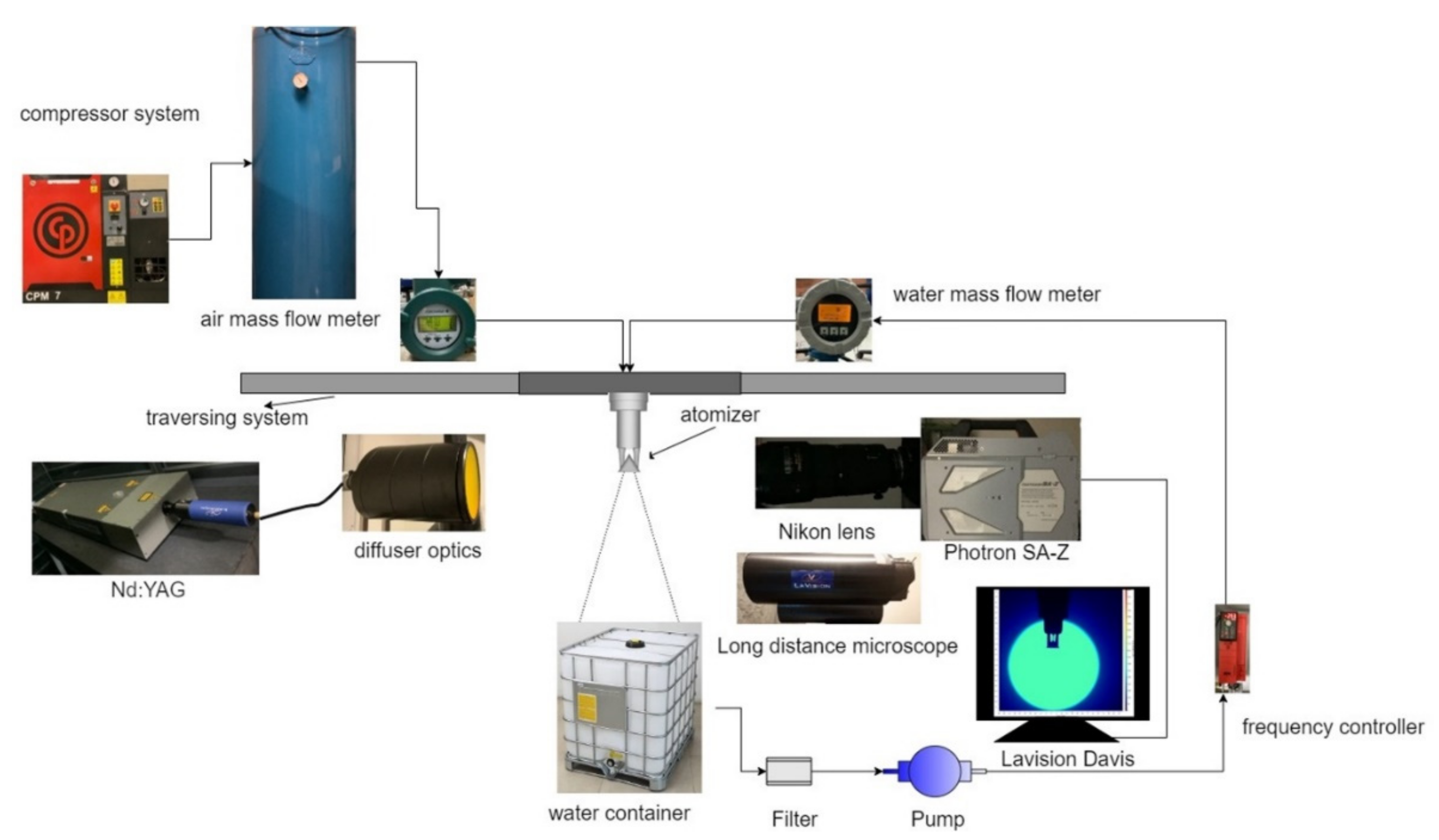
For visualizing the bluff body spray formation region, laser-based diffused backlight imaging was employed. The near-field region was illuminated with Nd: a YAG laser (model DM60-532-DH from Photonics Industries) with 532 nm wavelength and diffuser optics. The Photron camera (SA-Z model) was used with an extension (Nikon Micro lens (80–200 mm)) with an aperture setting of f/5.6 to provide a field of view (FOV) of 75 mm × 75 mm with a camera resolution (~8.36 pixels/mm). The images were recorded at a 10,000-repetition rate with a laser-controlled exposure time. The imaging was conducted at various operating conditions given in Table 2. The properties of the fluid are assumed to be standard temperature and pressure (STP) values at 293 K such that air viscosity (µg) = 1.8 × 10⁻⁵ Ns/m2; surface tension (σ) = 0.072 N/m in the current experiments. Air density (ρg) varied accordingly as per air mass flow rate inside the inner cavity. The mean droplet size measurements at various spatial locations for the dense spray were conducted using the dual-cavity solid-state (Nd: YAG) laser. The laser light with ~130 ns pulse width pulsed at 10 kHz with 10 mJ energy. A diffuser plate attached to the edge of the laser optics ensures uniform laser light and shifts the laser spectrum from λ = 532 nm to higher wavelengths (orange) due to fluorescence phenomena. Images of the downstream spray region were captured with a high-speed 12-bit monochrome CMOS-based camera (Photron SA-Z model), as shown in Figure 3.
Table 2.
Experimental working conditions for all atomizer configurations.

Figure 3.
Schematic for spray formation region imaging and shadowgraphy imaging for drop size measurements.
The long-distance microscope (Maksutov Cassegrain catadioptric QM1) by Questar is mounted in front of the camera, providing (1.6×) in-built image magnification. Droplet size measurements were performed using the ParticleMaster package included in the Davis 10.1 imaging software (2020) provided by LaVision GmbH, Göttingen, Germany. A barrow lens (2.0× zoom) provided a camera resolution of ~186.60 pixels per mm. This corresponds to imaging ~5.4 microns per pixel in a 1024 × 1024-pixel image. Depth of field (DOF) calibration was performed using a calibration plate with black dot area patches ranging from 20 to 400 μm. The depth-to-size ratio (DSR) is ~16.6/1 and the z-axis uncertainty is 3.70 mm. The pre-processing raw images and droplet detection parameters are tabulated (Table 3).
Table 3.
Settings for ParticleMaster software.
The software limitations allowed the drop sizes calculation to be 10 µm–2000 µm. The experiment was repeated in several cases to check the uncertainty of the droplet size measurement (accounting for a 1.5% change in mean droplet size).
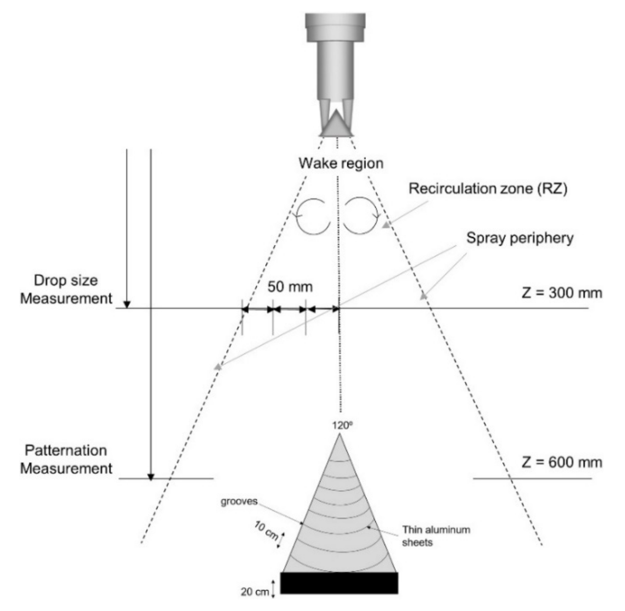
Five-hundred images at a 1 kHz rate were recorded as SMD converges to a single value after 300 images for the liquid volume employed. To ensure proper illumination and brightness of the captured images, laser intensity was altered appropriately through current (amperes) for different ranges of fluid flow rates. The images are taken 300 mm downstream from the nozzle-cone exit as the highly dense spray region hinders the near nozzle region imaging. The heavy mist formation clouding the images was misinterpreted collectively as the bigger droplets. The schematic for the drop size measurement and patternation locations is shown in Figure 4.

Figure 4.
Schematic for measurement locations for drop size measurements and patternation.
3. Results
3.1. Spray Structure
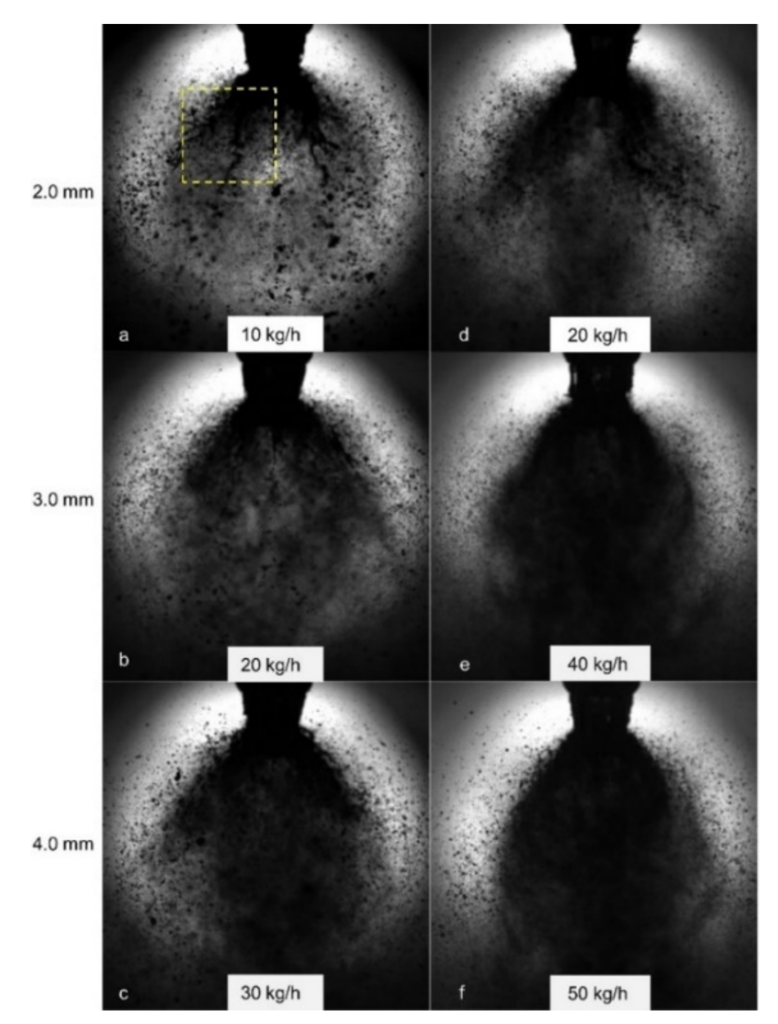
The near-atomizer region was visually studied for the spray formation dynamics for different fluid flow rates. The larger field of view (FOV) imaging renders the spray formation through liquid sheet-bluff body impact. The spray formation images depict the effect of liquid loading for moderate airflow rates for all atomizer configurations (Figure 5). For the 2.0 mm atomizer configuration, the spray-dendrite-like structure was rendered visible with an increment in liquid flow rate from 100 kg/h to 300 kg/h (Figure 5a,d). The ensemble of droplets/spray was more dispersed with larger air-orifice diameters (3.0 mm and 4.0 mm); this might be due to larger air mass flow, as shown in Figure 5b,c. The increase in the fraction of larger droplets is evident as the liquid flow rate increased from 100 kg/h to 300 kg/h for all atomizer configurations (Figure 5e,f). For 100 kg/h liquid flow rate, the droplets formed in the narrow drop size range, with a more uniform drop fragment size range with increased air jet diameter (Figure 5c). The spray angle is broader for a higher liquid flow rate (300 kg/h) for all the atomizers due to the relatively larger liquid momentum imparting higher radial momentum after impacting the bluff body. Note the laser light intensity (in amperes) also affects the spray structure imaging as higher intensity corresponds to lesser obstruction by the mist-like particle showing bright white spots, as shown in Figure 5c. The curved spray angle decreases slightly with an increase in air-jet diameter from 2.0 mm to 4.0 mm atomizer due to more airflow rate steering the droplets in the spray axis direction. The bifurcation structure is visible in the 2.0 mm atomizer, especially at a low airflow rate and higher liquid flow rate (say, 300 kg/h), as depicted in Figure 5d. Additionally, the ligament structure protrudes downstream of the spray axis, especially at higher liquid flow rates. This may explain the moderately large droplet size at the downstream position of the spray axis for the 2.0 mm and 4.0 mm atomizer configurations.
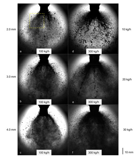
Figure 5.
High-speed imaging pictures depicting the spray formation at varying liquid flow rates for different airflow rates (yellow dotted line region are analyzed in Figure 6).
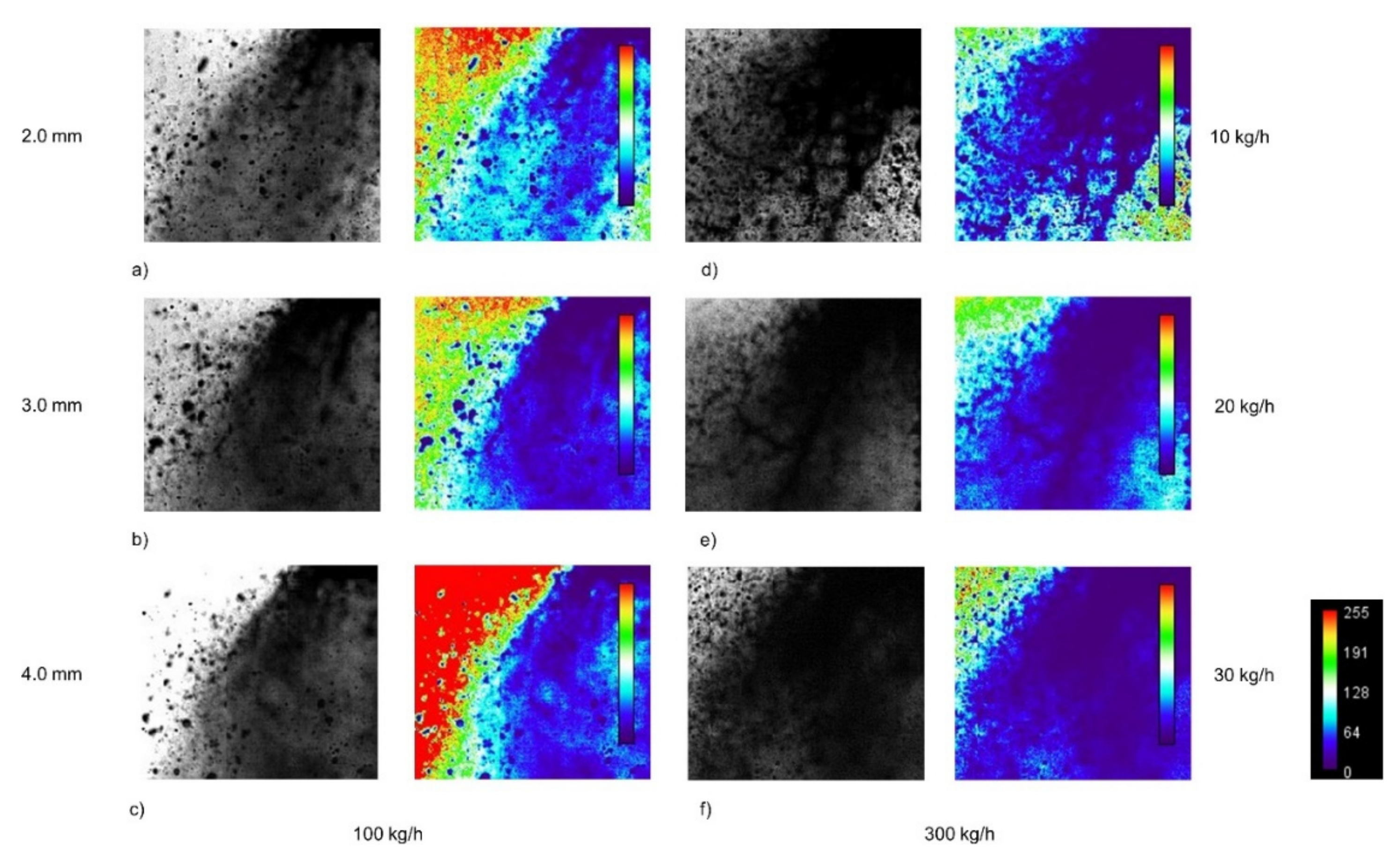
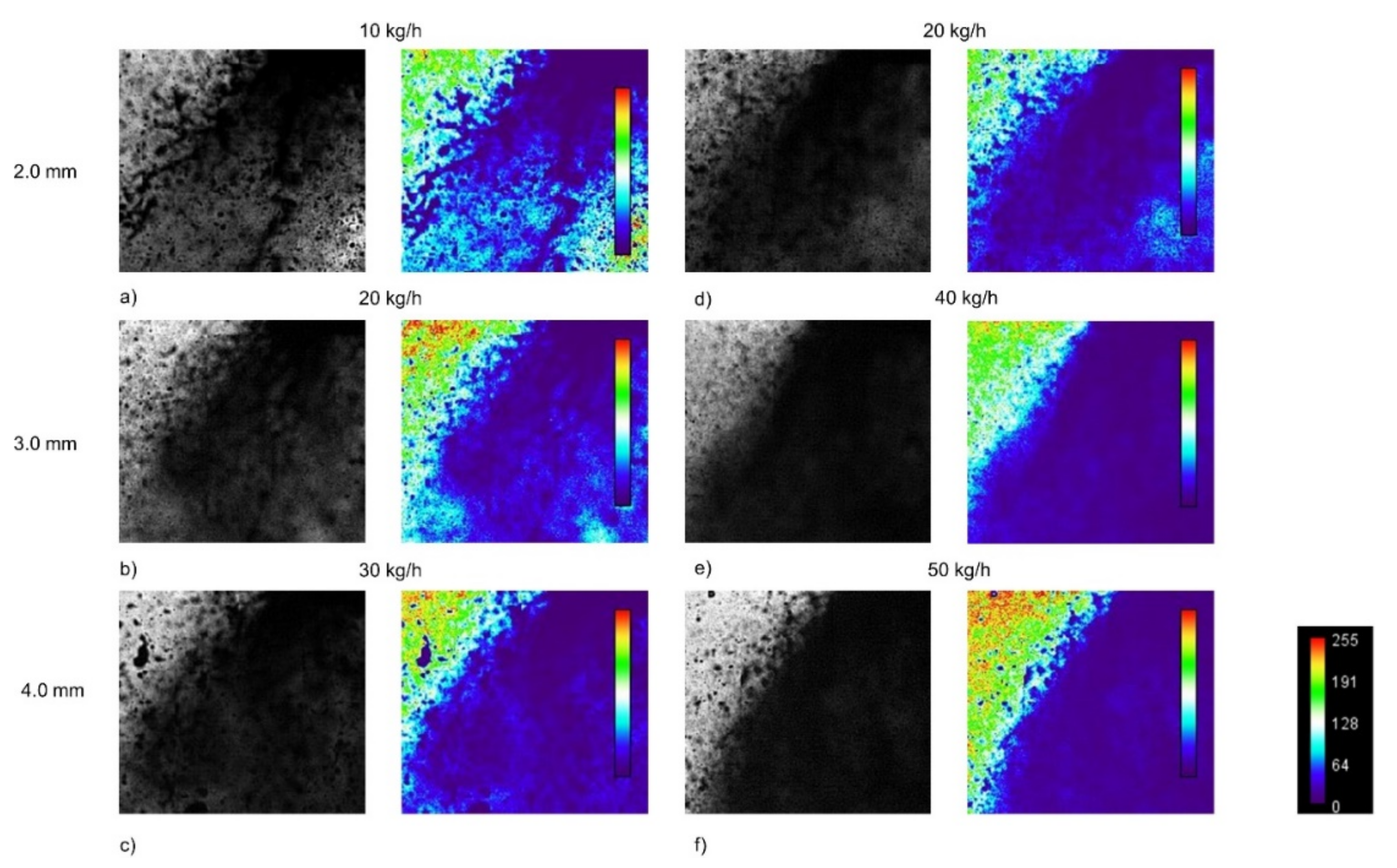
The intensity contours are generated using the HeatMap Histogram plugin in ImageJ (Schneider et al. [43]). A rectangular region of interest (ROI) (marked in dotted yellow) of 26 mm × 23 mm was cropped from the larger FOV spray images. The raw image is then sharpened and converted into an 8-bit image for processing. This plugin counts the pixels for the grayscale intensity value (0 for black and 255 for white), and then transforms it into a heat map with a color grading bar. The dark blue region (0–64 value) denotes the ligaments/droplets that eject out of the spray-bluff body impact, as shown in Figure 6. The lighter blue region (64–128) surrounding the darker blue region depicts the mist formation (Figure 6f). The mist formation increases with the increase in liquid loading due to high impact momentum, resulting in many finer droplets being formed along with bigger droplets for all atomizers.
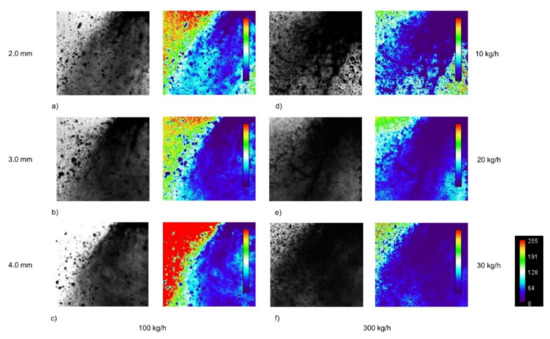
Figure 6.
Instantaneous high-speed imaging close (cropped) depicting the spray formation at varying liquid flow rates for different airflow rates (a,d) 10 kg/h, (b,e) 20 kg/h, and (c,f) 30 kg/h (0 means dark and 255 means white).
At a liquid flow rate of 200 kg/h (Figure 7), increasing the airflow slightly reduces the spray angle (curve boundary) for all atomizer configurations due to the higher axial momentum/velocity of the air jet. After hitting the bluff body (cone), the newly formed droplet stream is less scattered. As the air velocity increases, the spray becomes more even, and more mist is formed due to the rapid air–liquid interaction and spray bluff body (cone) effect. Droplet size decreases with increasing air velocity. This is because the mist is formed due to the high collisional momentum of the air and liquid, and the high air mass flow rate increases the radial momentum and creates a large shear environment (Figure 7e,f). The darker region in the heat map exhibits more dense liquid fragments with increased airflow rate for a given liquid flow rate (200 kg/h), as shown in Figure 8. In the 4.0 mm air-jet diameter atomizer configuration, the higher air mass flow rate (see Figure 8f) provides added darker (blue) regions due to more uniform ligaments/globules spread in the nearby region owing to the more prominent air–liquid interaction with increased air mass flow. The curved spray boundary becomes narrower with an increased air mass flow rate for all atomizer configurations.

Figure 7.
High-speed imaging pictures depicting the spray formation at 200 kg/h liquid flow rate for various airflow rates (yellow dotted line region are analyzed in Figure 8).
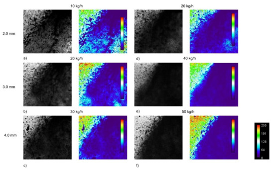
Figure 8.
Instantaneous high-speed imaging (cropped) depicting the spray formation at 200 kg/h liquid flow rate for various airflow rates (a) 10 kg/h, (b) 20 kg/h, (c) 30 kg/h, (d) 20 kg/h, (e) 40 kg/h, (f) 50 kg/h.
3.2. Mean Drop Size (SMD)
The drop sizes were measured from the raw spray images at three radial locations (50 mm, 100 mm, and 150 mm) and one axial location (0 mm) at 300 mm downstream from the atomizer exit. The mean diameter calculation was performed in terms of SMD. Kowalczuk et al. [44] defined the surface-volume mean diameter such that the total surface energy of polysized spherical objects is equal to the total surface energy of identical spherical objects. It is characterized by drop size fractions as given in Equation (2)
where ni and Di are the number and diameter, respectively, of a droplet in a particular size fraction.
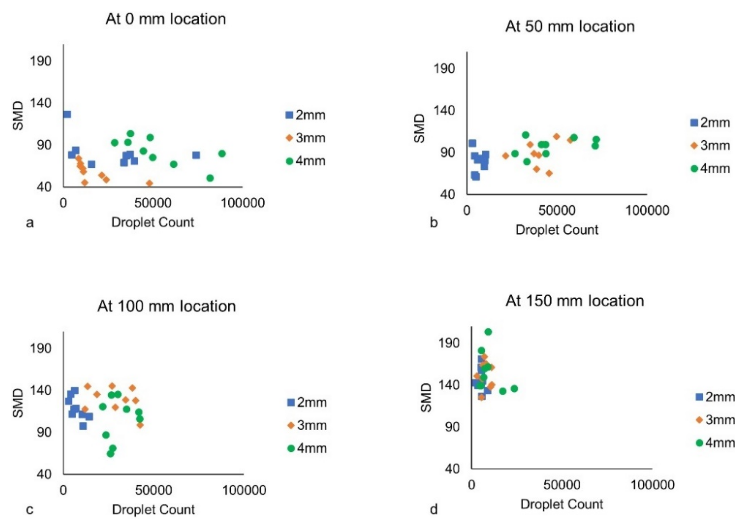
The SMD (D32) was plotted against the droplet count for all locations for different flow operating conditions (Figure 9). The droplet number density is maximum at the central axial location (0 mm), as shown in Figure 9a, for all atomizers with maximum and minimum droplet number density in 4.0 mm atomizer and 2.0 mm atomizer, respectively. The low droplet number density in the 2.0 mm atomizer might be due to the low air mass flow rate and weak reflected shock strength resulting in lesser air–liquid interaction on the liquid fragments. In contrast, the high mass flow rate and the high reflected shock strength might be the reason for the large droplet density (in the case of the 4.0 mm atomizer), ranging from mist-like droplets to larger globular droplets. The droplet count decreases gradually as we move radially towards the spray periphery with a comparable droplet count at a far radial location (150 mm) between all atomizers. The combined air–liquid axial and radial momentum strength (post bluff body impact) dictates the droplet number density at far radial locations as air entrainment and aerodynamic drag inhibit the spray spread.
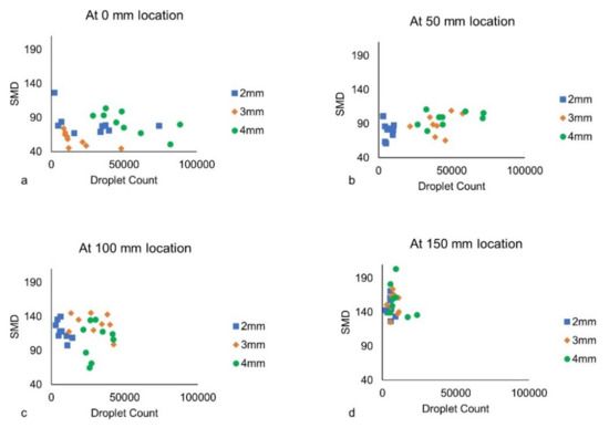
Figure 9.
Scatter plot showing the SMD vs droplet count at (a) 0 mm, (b) 50 mm, (c) 100 mm, and (d) 150 mm location for all atomizers.
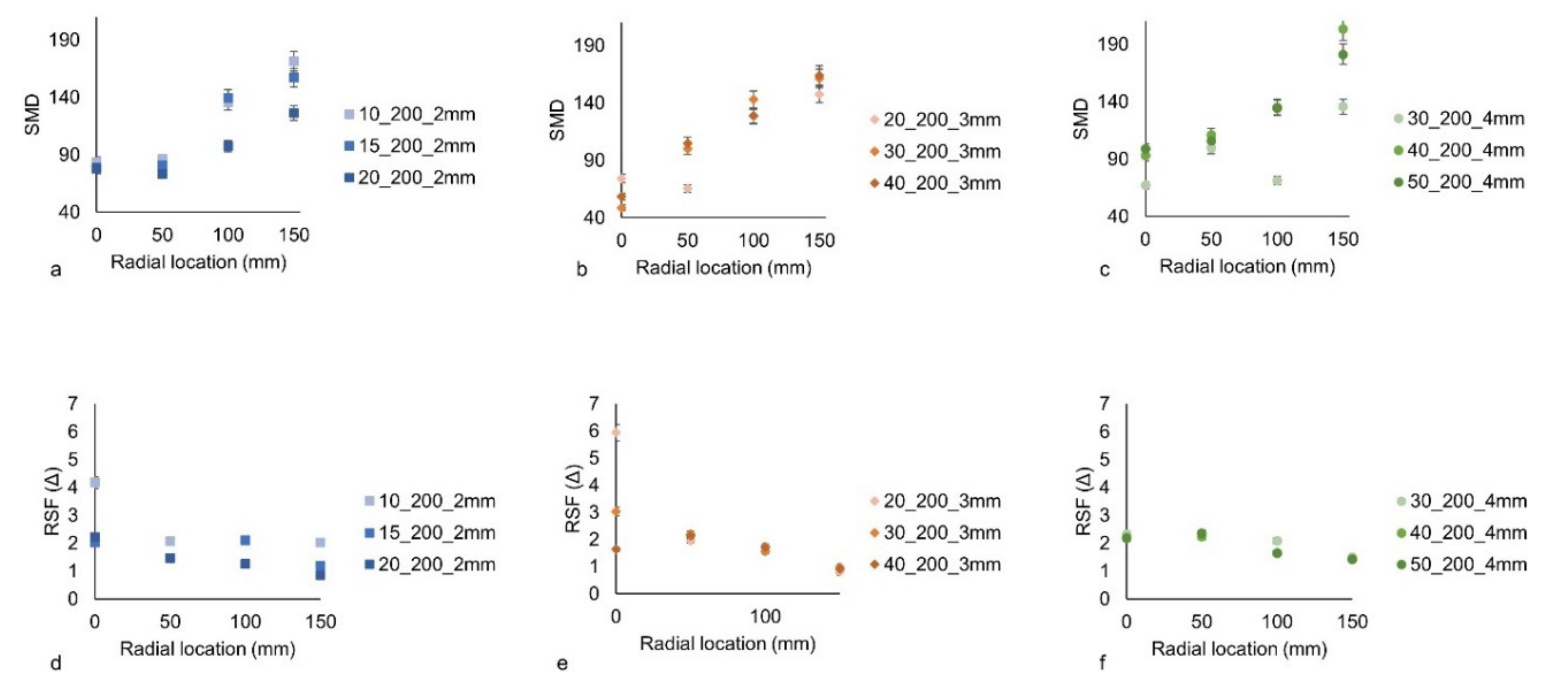
The SMD and RSF (Δ) were plotted against all radial locations for a given airflow rate (30 kg/h) with changing liquid flow rates in Figure 10. The mean droplet size (SMD in µm) and the range of droplet sizes formed (defined by relative span factor (RSF)) are correlated in such a way that smaller droplet size corresponds to a larger range of droplets formed (in terms of size), though mainly smaller droplets are formed in such cases and vice versa. The droplet count also affects the correlation between SMD and RSF (Δ) for a given location. The spray uniformity (drop size range) in addition to mean drop size influences the combustion characteristics.
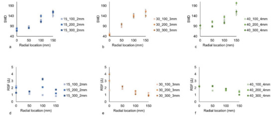
Figure 10.
Plot showing the effect of liquid loading on the SMD (a–c) and RSF (d–f) values at various radial locations for all atomizer configurations.
Furthermore, the RSF (Δ) is considered to be a good alternative for representing the drop size distribution as it is independent of any theoretical distribution function (Bossard et al. [17]). It is defined by percentile-based diameters such as D0.1, D0.5, and D0.9 as the diameters containing 10%, 50%, and 90% (by volume) of droplets smaller than these diameters, respectively. Please note that the RSF and relative span factor are used interchangeably with the symbol Δ. It is denoted by Equation (3)
The SMD monotonously increases as we move away from the spray centerline in the radial direction. At 0 mm axial location, the SMD is comparable for 2.0 mm and 4.0 mm atomizers but relatively low for the 3.0 mm atomizer. The smaller SMD values might be due to a smaller number of droplets being formed (see Figure 9a) at the spray centerline subjected to the intensity of the spray-bluff body impact. The RSF (Δ) values are higher for the 3.0 mm atomizer than for the other two atomizer configurations at the 0 mm axial location. The RSF value was more dispersed as the liquid flow rate increased from 100 kg/h to 300 kg/h for the 2.0 mm atomizer at the 100 mm radial location. The spread is caused due to the moderate increase in the droplet count with higher liquid flow rates (say, 300 kg/h). In contrast, for the 4.0 mm atomizer, RSF values remain in a narrow band of ~1–2 for all radial locations due to the large number of droplets formed owing to the better air–liquid interaction, though the droplet count monotonously decreases with the increased radial location.
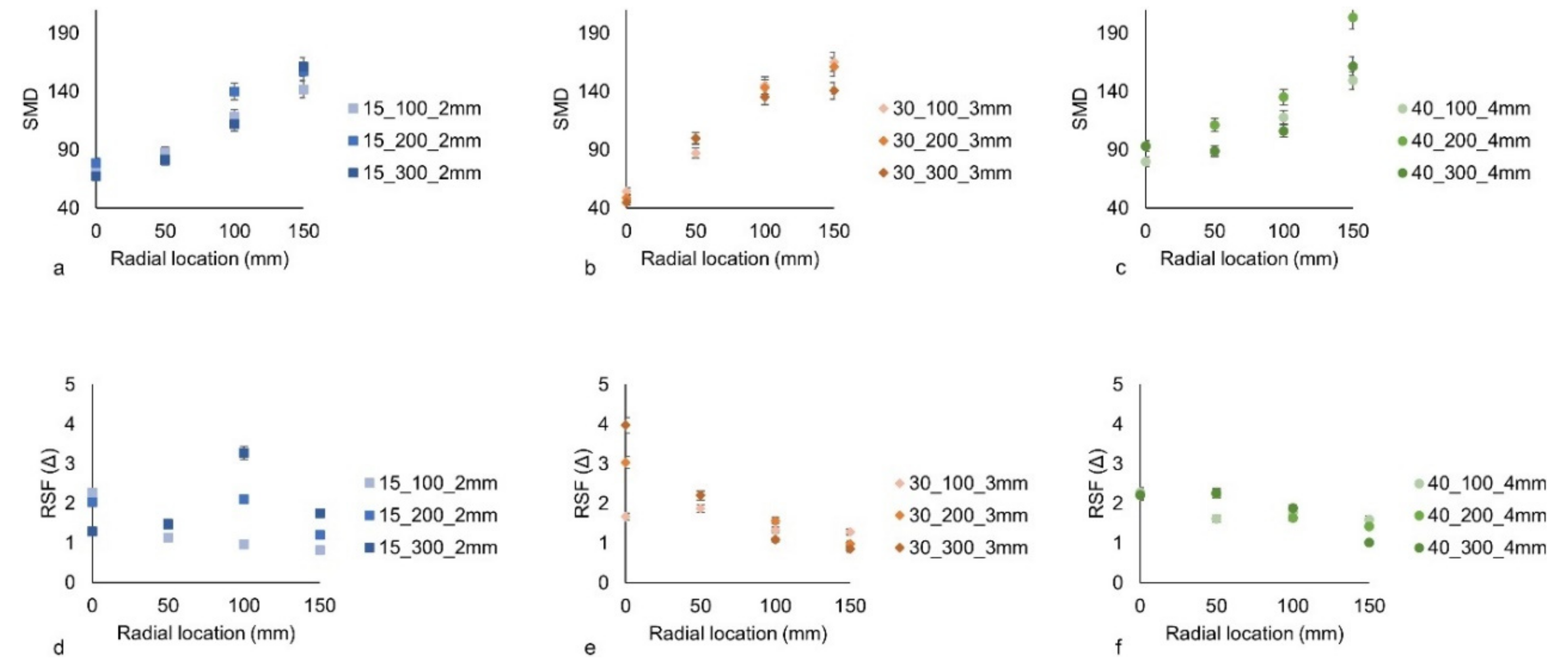
The SMD was plotted against all radial locations for a 200 kg/h liquid flow rate with varying airflow rates for three different atomizers in Figure 11. The same trend was observed as SMD increases gradually with an increase in the radial location. The difference in the SMD value with the increment in airflow rates is notable at far radial locations such as 100 mm and 150 mm for all atomizers. The noticeable difference is due to both spray-bluff body impact momentum imparting radial momentum and aerodynamic interaction between the two-phase spray flow. SMD lies in the range of ~45–90 µm and ~125–200 µm at the spray centerline (0 mm location) and far radial location (150 mm), respectively, for all three atomizer configurations.
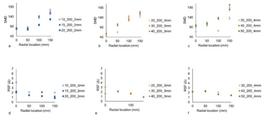
Figure 11.
Plot showing the effect of ALR on the SMD (a–c) and RSF (d–f) values for all atomizers at various radial locations.
The RSF (Δ) marginally decreases with an increment in the radial direction and converges to ~1. At the 0 mm radial location, the RSF value substantially differs with the change in airflow rates in 2.0 mm and 3.0 mm diameter atomizers, whereas the RSF value coincides with the 4.0 mm atomizer. The large difference in the droplet count with variation in airflow rates might cause a large differential in RSF values for 2.0 mm and 3.0 mm atomizers. In contrast, despite the relatively large number of droplets formed, the RSF value coincides at the ~1.7–2 value at all radial locations for all airflow rates. The influence of airflow rates on the RSF (or droplet size ranges) is prominent for the 2.0 mm atomizer; the influence is more pronounced at a far radial location (150 mm).
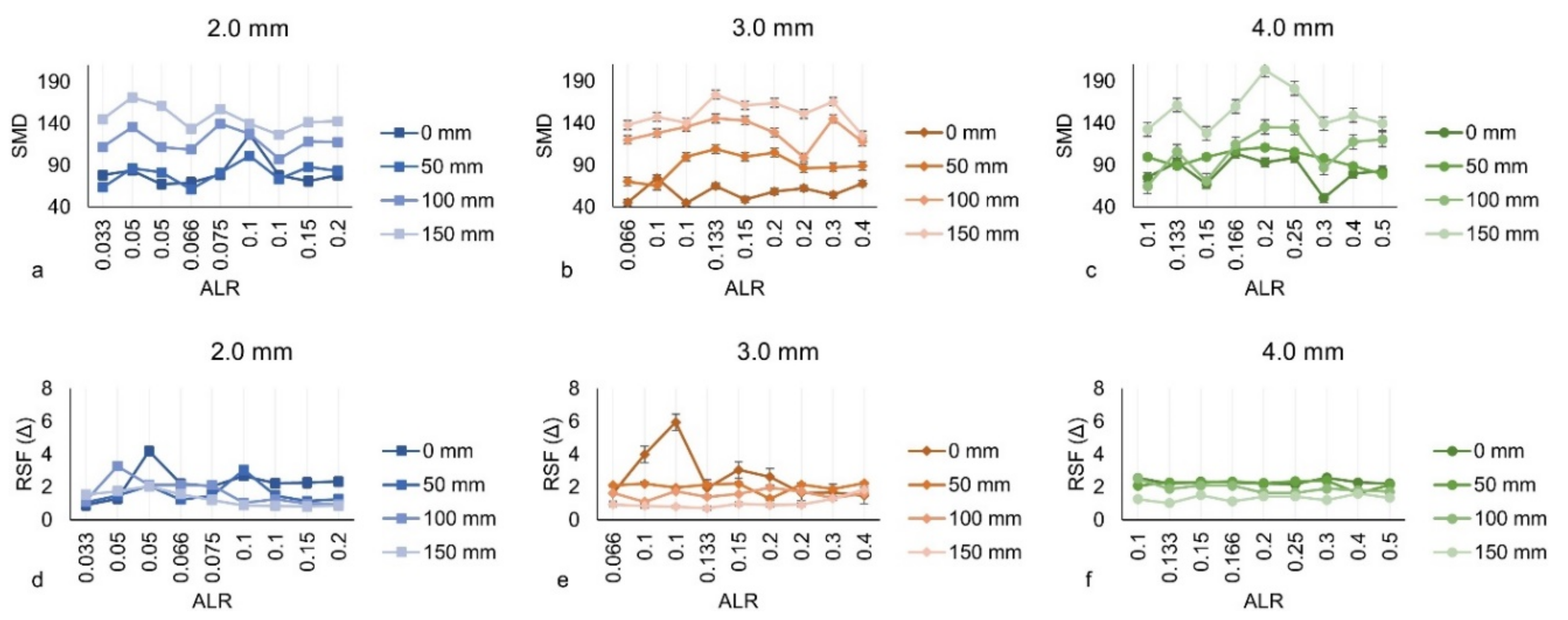
The line plots (Figure 12) depict the SMD variation with the ALR values at all radial locations for all three atomizer configurations. The zigzag variation of the SMD value with the air-to-liquid ratio (ALR) was observed for all atomizers. SMD is minimum and maximum at near-axis locations (0 mm) and far radial locations (150 mm), respectively, due to the highly intense air–liquid interaction in the former owing to both spray-bluff body impact and high shearing effect due to the high-speed airflow. The imparted spray radial momentum (after bluff body impact) results in bigger size droplets due to milder aerodynamic interaction, especially at far radial locations. The RSF (Δ) value follows the reverse trend with variation in radial locations as the RSF value is maximum and minimum at spray axis location (0 mm) and far radial location (150 mm), respectively. The RSF value fluctuated in both 2.0 mm and 3.0 mm atomizers against the lower ALR values (<0.1) for all radial locations, whereas RSF stabilized after the ALR value of 0.1. For the 4.0 mm atomizer, RSF (Δ) remains stable against all ALR values in the range (0.1–0.5) for all radial locations, providing a more uniform and steady spray in terms of drop size ranges.
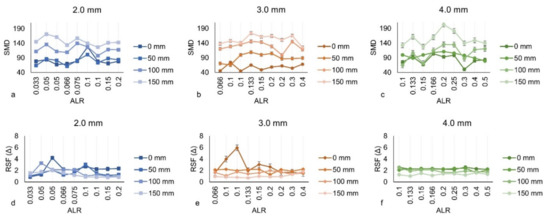
Figure 12.
Line plot showing SMD (a–c) and RSF (d–f) against the ALR values at various radial locations for all atomizer configurations.
3.3. Drop Size Distribution (DSD) and Excentricity Plots
The droplet size distribution (DSD) complements the mean drop size (SMD) in characterizing the sprays. Volume-normalized DSD and the cumulative distribution function curve (red) are plotted for spray axial location (0 mm) in Figure 13. The DSD is unimodal and asymmetric and slightly biased towards the smaller droplets for all atomizers. The distribution peak is approximately 100 µm for both 2.0 mm and 4.0 mm atomizers, whereas the distribution peak reaches ~50 µm for 3.0 mm atomizers. Moreover, the DSD spread is wider in the case of 2.0 mm and 4.0 mm atomizers than 3.0 mm atomizers due to the small fraction of bigger droplets formed at the far radial location (150 mm) in the former, owing to the larger inertia. The 3.0 mm atomizer configuration cumulative distribution curve exhibited that 80% of the droplet size (by volume) falls under ~100 µm, which might be due to the optimum air mass flow rate leading to high spray-bluff body impact momentum, resulting in a plethora of smaller droplets under the bluff body area.
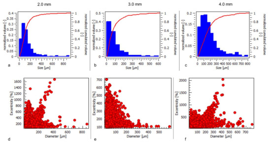
Figure 13.
Histogram indicating the volume-based drop size distribution (top) and excentricity (%) plot (bottom) at 200 kg/h liquid flow rate for airflow rates (a,d) 15 kg/h, (b,e) 30 kg/h, and (c,f) 40 kg/h.
The secondary droplets formed after impacting the bluff body are of irregular elliptical/globular shape. The excentricity plot (Figure 13) depicts the shape of the resulting droplets such that 100% excentricity means a completely spherical droplet. The excentricity is defined as the ratio of the long axis to the short axis of the non-spherical droplet. The shape of the secondary droplets depends not only on the impact of a bluff body but also on the liquid film formed on the bluff body as a result of the impinging liquid fragments (Yarin [25]). In the 3.0 mm atomizer, the excentricity (%) follows an inverse relationship with the droplet diameter such that bigger droplets have low excentricity (%) and vice versa. Conversely, for 2.0 mm and 4.0 mm atomizers, it follows an inverse trend with a linear relationship for a few droplet diameters. The comparatively low excentricity in the former case (3.0 mm atomizer) might be due to liquid fragments hitting the liquid film formed on the bluff body owing to the moderate air flow rate and low reflected shock strength. However, excentricity reaches 1000% for some droplets, which might be because some dark objects (droplets) were measured as groups leading to high excentricity%. The majority (~95%) of the droplets fall under 400% excentricity (which can be perceived by the blurriness of the red dots due to overlapping). It is important to mention that the drop measurements were carried out in a highly dense spray region.
DSD and cumulative distribution functions (curves) are plotted for a constant airflow rate (depending on the atomizer configuration) and a liquid flow rate of 200 kg/h for three radial positions 50 mm apart (Figure 14). DSD is unimodal and asymmetric and slightly skewed at smaller droplets. The DSD spread tends to shift towards bigger droplet sizes with the increase in air-jet diameters for all radial locations.
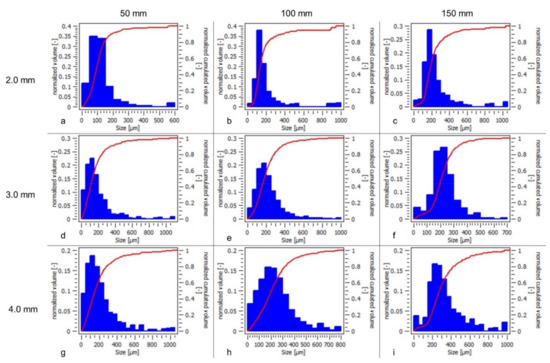
Figure 14.
Histogram indicating the volume-based drop size distribution (blue) at 200 kg/h liquid flow rate for different airflow rates (a–c) 15 kg/h, (d–f) 30 kg/h, and (g–i) 40 kg/h, respectively, for three radial locations.
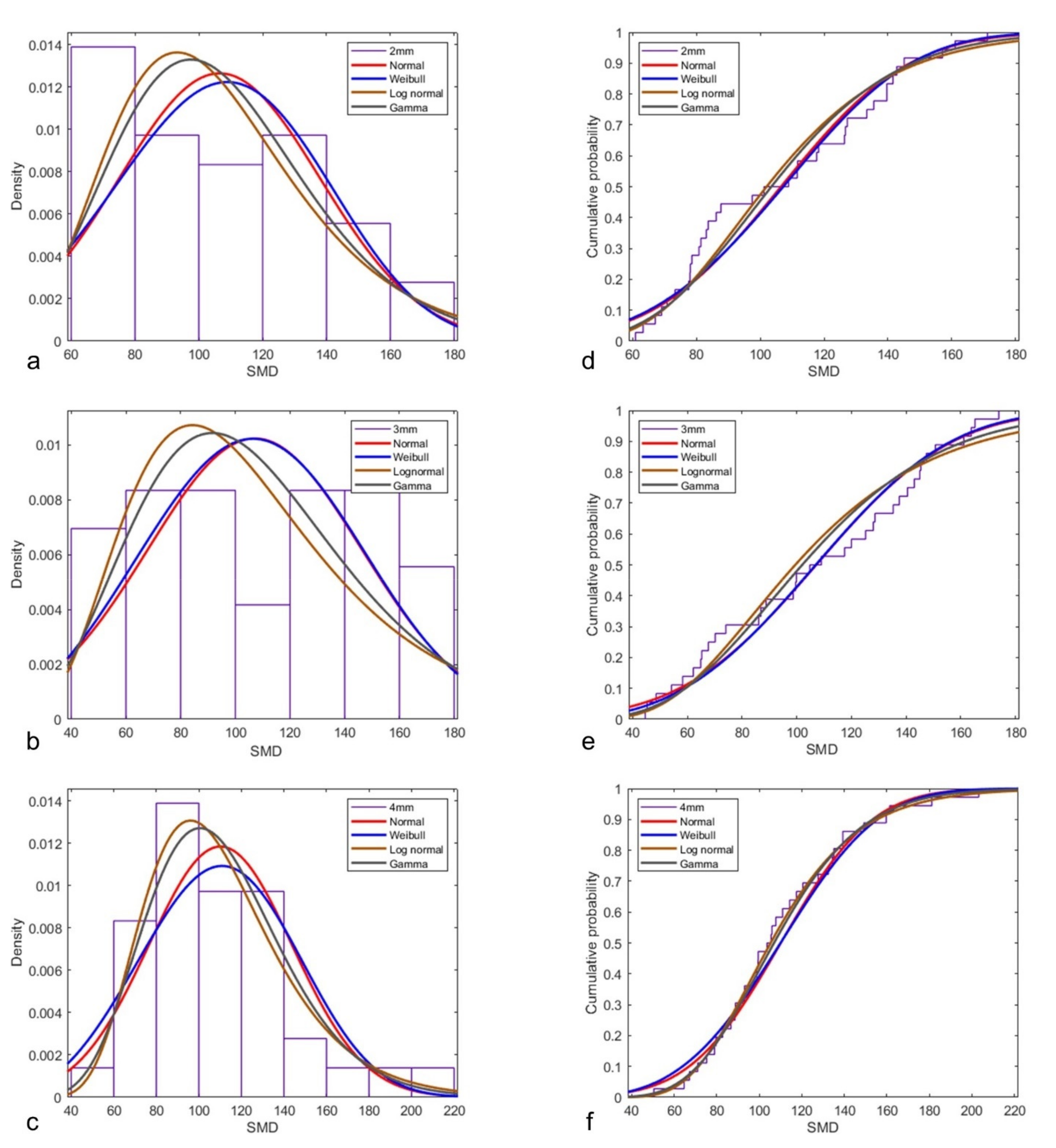
The cumulative distribution curve exhibited DSD spread such that 80% of the droplet size (by volume) falls under ~150–225 µm for the 2.0 mm atomizer, ~200–250 µm for the 3.0 mm atomizer, and ~275–400 µm for the 4.0 mm atomizer, respectively. The air mass flow rate (or relative air velocity) and the reflected shock strength might be the reason influencing the secondary droplet size formation. This results in determining the spray-bluff body impact momentum, also affecting radial momentum which led to the intensity variation in the aerodynamic disintegration of the droplets at far radial locations. For the sake of completeness, the DSD curve fit built on various distribution functions (Normal, Weibull, log-normal, etc.) is shown in Figure A1 (Appendix A).
The droplet excentricity (in %) is plotted for three radial locations 50 mm apart, for fixed airflow rates (depending on the atomizer configuration) and fixed liquid flow rate (200 kg/h) (Figure 15). In general, the excentricity (%) follows an inverse relationship with the droplet diameter such that bigger droplets have low excentricity and vice versa. For the 2.0 mm atomizer, the excentricity (%) values are lower than the other two atomizer configurations. On the other hand, for the 3.0 mm and 4.0 mm atomizers, it follows the same inverse trend with a linear relationship for a few droplet diameters. The excentricity (%) reduces with the increase in the radial locations due to the milder aerodynamic interaction subjected to lower radial momentum and drag caused due to air entrainment. The comparatively low excentricity in the 2.0 mm atomizer might be due to the lower airflow rate, resulting in lesser radial momentum of the liquid fragments after impacting the bluff body, leading to less turbulent air–droplet interaction.
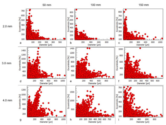
Figure 15.
Plot showing the excentricity (%) at 200 kg/h liquid flow rate for airflow rates (a–c) 15 kg/h, (d–f) 30 kg/h, and (g–i) 40 kg/h, respectively, for three radial locations.
3.4. Patternation Technique
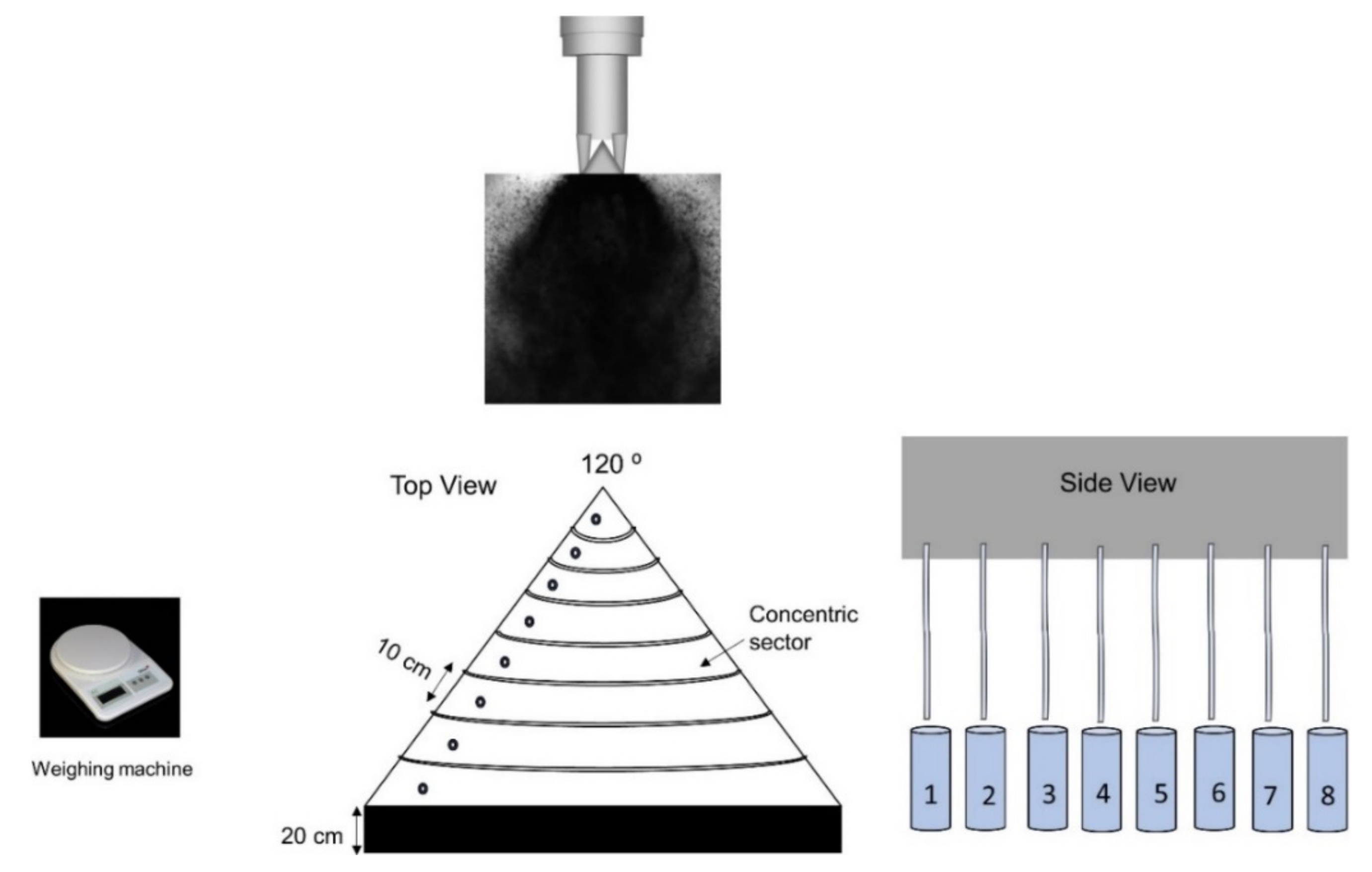
The patternation was performed with a concentric compartment 120° (conical) sector Patternator as seen in Figure 16. The spray pattern (radial spray mass distribution) was measured with an atomizer centered above the vertex of the conical Patternator. The liquid sprays were ejected down into the concentric compartments, from which liquid is drained and collected into one-liter bins. The bins were then weighed to obtain the liquid mass flux per each concentric compartment. Each bin represents the liquid volume contained in a particular concentric sector. The entire process is repeated for each run for 360 s. For a few cases, repetition was performed to check the uncertainty (<1%) in the mass flux data collection. The mass flux density (kg/m2.s) contours were plotted sector-wise such that liquid mass divided by the corresponding sector area for a given time (i.e., 360 s) is depicted in each working condition. The spray pattern for the 120° sector for a 2.0 mm atomizer at a 10 kg/h airflow rate and 200 kg/h liquid flow rate is shown in Figure 17. In this case, the spray area spreads out evenly, with more liquid mass concentrated in the region near the center and decreasing towards the edges of the spray. For the given fluid flow rates, the spray pattern also indicates spread in terms of spray coverage area.

Figure 16.
Schematic of the 120° Patternator design and in-flow process.
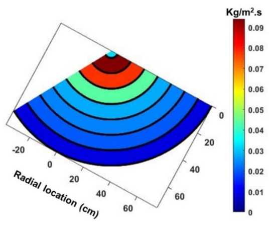
Figure 17.
Contour plot for mass flux for one measurement for 120° sector.
The contours for spray pattern for the sector azimuthally for all atomizer configurations at fixed corresponding middle airflow rates with varying liquid flow rates are plotted in Figure 18. For a 2.0 mm atomizer with a 15 kg/h airflow rate, spray coverage gradually increases with increasing liquid loading as one moves from 100 kg/h to 300 kg/h, with a more uniform spread for the 300 kg/h liquid flow rate. In contrast, for other atomizers (3.0 mm and 4.0 mm), the spray mass is relatively more concentrated in the central region, which might be due to the larger airflow rates employed with corresponding lower velocities affecting the trajectories of the droplets under the bluff body area. The bluff body impact momentum dictates the spray spread, and thus the uniformity in the spray pattern, which might cause a plethora of droplets (by volume) in the low-pressure recirculation zone under the bluff body area. Spray pattern uniformity is crucial for ideal liquid–air interaction, which affects air–liquid mixing. The pattern symmetry is poor at relatively low air and liquid flow rates due to the underdeveloped spray leading to the large liquid mass splashing out of the sectors. In contrast, pattern symmetry is also disturbed at higher fluid flow rates due to the air entrainment disrupting the two-phase spray flow, promoting the large quantity of spray (in volume) entraining towards the spray axis.
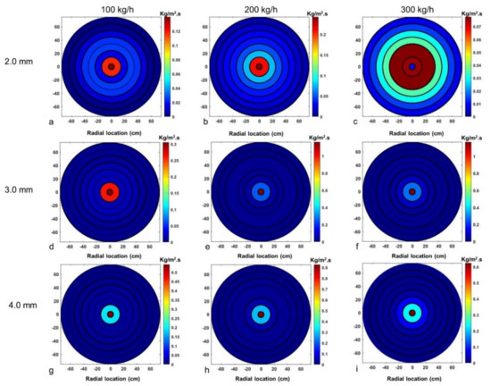
Figure 18.
Contour plot for mass flux distribution for three liquid flow rates for different airflow rates (a−c) 15 kg/h, (d−f) 30 kg/h, and (g−i) 40 kg/h, respectively.
The contours for the spray pattern for the sector azimuthally for all atomizer configurations at a fixed liquid flow rate (200 kg/h) with changing airflow rates are plotted in Figure 19. The reverse trend for the ALR value is observed such that for a 2.0 mm atomizer, spray coverage decreases gradually with the increase in the ALR value as we move from 10 kg/h airflow rate to 20 kg/h airflow rate, with a more uniform spread for the lower airflow rate. Simultaneously, for other atomizers (3.0 mm and 4.0 mm), the spray mass showed a similar pattern of decreasing spray coverage with the increase in the ALR, which might be due to the bluff body spray impact momentum resulting in a larger number of smaller droplets (large by volume) entrained into the recirculation zone.
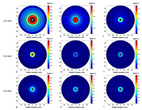
Figure 19.
Contour plot for mass flux distribution at various airflow rates at a given 200 kg/h liquid flow rate for all atomizer configurations for different airflow rates (a) 10 kg/h, (b) 15 kg/h, and (c) 20 kg/h; (d) 20 kg/h, (e) 30 kg/h, and (f) 40 kg/h; and (g) 30 kg/h, (h) 40 kg/h, and (i) 50 kg/h, respectively.
4. Conclusions
The objective of this study is spray characterization of different atomizer designs based on the complex air–liquid interaction within the atomizer type. The high-speed airflow leading to bluff body-reflected shock waves interacting with the liquid sheet/ligaments leading to the formation of the cloud of droplets (mist-like) along with interconnected ligament structures protruding downstream at the bluff body streamline direction and at the spray centerline. Droplet number density is higher at the spray centerline location (0 mm) except for the 3.0 mm atomizer which has comparatively less droplet density. Droplet number density decreases as we move along the radial direction away from the spray axis. In general, SMD increases with increasing radial position from the centerline of the spray. This is attributed to the impact dynamics of the spray bluff body, resulting in a milder aerodynamic breakup of the larger droplets. This is due to the smaller droplets being entrained into the low-pressure recirculation zone under the bluff body area, as evidenced by the larger droplet number density observed at the spray centerline. Higher SMD values were observed at 150 mm radial location for higher airflow rates for different atomizers.
The RSF (Δ) follows the opposite trend, gradually decreasing away from the spray centerline. The high RSF value at the spray centerline indicates that owing to ligament breakup, a large range of droplet sizes are formed such that finer mist-like drops are formed due to the reflected shock interaction with the fragmented sheet in addition to the bluff body impact effect. Low RSF values at a higher radial location depict the comparably larger equisized droplets formed as larger droplets followed the bluff body trajectory, whereas smaller size droplets are entrained into the central recirculation zone under the bluff body area. DSD and cumulative distribution become wider with the increase in the radial location, with broader drop size distribution formed with the increase in air-jet diameter such that 2.0 mm and 3.0 mm atomizer configurations displayed a more uniform (narrow) distribution than the 4.0 mm atomizer. Excentricity plots showed that droplet excentricity (%) follows an inverse relationship with the droplet diameter such that high diameter droplets have low excentricity (%) and vice versa, hinting at the intensity of the bluff body-influenced secondary droplet dynamics and the aerodynamic interaction. The spray pattern increases gradually with the increase in liquid loading and with the decrease in the ALR value. The slight variation in the spray pattern uniformity in different atomizer configurations depicts the distinct bluff body spray impact dynamics subjected to different air-jet diameter atomizers.
Author Contributions
Conceptualization, R.S. and J.L.; methodology, R.S. and J.L.; investigation, R.S.; resources, K.V. and D.B.; data curation, R.S.; writing—original draft preparation, R.S.; writing—review and editing, J.L.; visualization, R.S. and J.L.; supervision, K.V. and D.B.; project administration, K.V. and D.B.; funding acquisition, K.V. and D.B. All authors have read and agreed to the published version of the manuscript.
Funding
This research was funded by the Ministry of Education and Research of the Norwegian government.
Data Availability Statement
Not applicable.
Acknowledgments
The researchers would like to express gratitude for the financial assistance received from Wärtsilä Moss AS for the necessary equipment for the experimental setup.
Conflicts of Interest
The authors declare no conflict of interest.
Appendix A
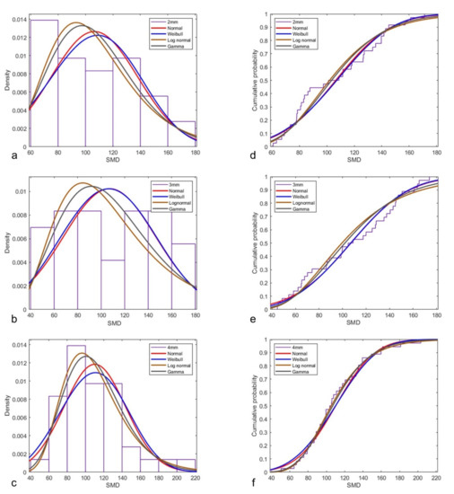
Figure A1.
Distribution fit includes all mean drop size (SMD) values (in µm) for all radial locations at varied fluid flow rates.
Figure A1.
Distribution fit includes all mean drop size (SMD) values (in µm) for all radial locations at varied fluid flow rates.
References
- Nasr, G.G.; Yule, A.J.; Bendig, L.G.G. Industrial Sprays and Atomization Design, Analysis and Applications; Springer: London, UK, 2002; ISBN 9781849968751. [Google Scholar]
- Kihm, K.D.; Chigier, N. Effect of Shock Waves on Liquid Atomization of a Two-Dimensional Airblast Atomizer. At. Sprays 1991, 1, 113–136. [Google Scholar] [CrossRef]
- Adiga, K.C.; Willauer, H.D.; Ananth, R.; Williams, F.W. Implications of droplet breakup and formation of ultra fine mist in blast mitigation. Fire Saf. J. 2009, 44, 363–369. [Google Scholar] [CrossRef]
- Chauvin, A.; Jourdan, G.; Daniel, E.; Houas, L.; Tosello, R. Experimental investigation of the propagation of a planar shock wave through a two-phase gas-liquid medium. Phys. Fluids 2011, 23, 113301. [Google Scholar] [CrossRef]
- Borisov, A.A.; Gelfand, B.E.; Natanzon, M.S.; Kossov, O.M. Droplet breakup regimes and criteria for their existence. J. Eng. Phys. 1981, 40, 44–49. [Google Scholar] [CrossRef]
- Issac, K.; Missoum, A.; Drallmeier, J.; Johnston, A. Atomization experiments in a coaxial coflowing Mach 1.5 flow. AIAA J. 1994, 32, 1640–1646. [Google Scholar] [CrossRef]
- Balaji, K.; Sivadas, V.; Radhakrishna, V.; Ashok Bhatija, K.; Sai Charan, K. Experimental Characterization of Intrinsic Properties Associated With Air-Assisted Liquid Jet and Liquid Sheet. J. Fluids Eng. 2018, 140, 051301. [Google Scholar] [CrossRef]
- Leboucher, N.; Laporte, G.; Carreau, J.L. Effect of the inner gas jet on annular liquid sheet atomization. In Proceedings of the 21st ILASS—Europe Meeting, Mugla, Turkey, 10–13 September 2007; pp. 1–5. [Google Scholar]
- Fu, H.; Li, X.; Prociw, L.A.; Hu, T.C.J. Experimental investigation on the breakup of annular liquid sheets in two co-flowing airstreams. In Proceedings of the 1st International Energy Conversion Engineering Conference IECEC, Portsmouth, VA, USA, 17–21 August 2003; pp. 1–11. [Google Scholar] [CrossRef]
- Lee, J.G.; Ghen, L.D. Linear stability analysis of gas-liquid interface. AIAA J. 1991, 29, 1589–1595. [Google Scholar] [CrossRef]
- Mates, S.; Settles, G.S. A study of liquid metal atomization using close-coupled nozzles, part 1: Gas dynamic behavior. At. Sprays 2005, 15, 1–22. [Google Scholar] [CrossRef]
- Mates, S.; Settles, G.S. A study of liquid metal atomization using close-coupled nozzles, part 2: Atomization behavior. At. Sprays 2005, 15, 41–59. [Google Scholar] [CrossRef]
- Fritsching, U. Droplets and particles in sprays: Tailoring particle properties within spray processes. China Particuology 2005, 3, 125–133. [Google Scholar] [CrossRef]
- Kulkarni, A.P.; Deshmukh, D. Spatial Drop-Sizing in Airblast Atomization-An Experimental Study. At. Sprays 2017, 27, 949–961. [Google Scholar] [CrossRef]
- Lefebvre, A.H.; Mcdonell, V.G. Atomization and Sprays, 2nd ed.; CRC Press: New York, NY, USA, 2017; ISBN 9781498736268. [Google Scholar]
- Lovett, J.A.; Mick, W.J. Development of a Swirl and Bluff-body Stabilized Burner for Low-NOx, Lean-Premixed Combustion. In Proceedings of the ASME 1995 International Gas Turbine and Aeroengine Congress and Exposition, Houston, TX, USA, 5–8 June 1995; pp. 1–8. [Google Scholar]
- Bossard, J.A.; Peck, R.E. Droplet size distribution effects in spray combustion. Symp. (Int.) Combust. 1996, 26, 1671–1677. [Google Scholar] [CrossRef]
- Li, X.; Shen, J. Experimental study of sprays from annular liquid jet breakup. J. Propuls. Power 1999, 15, 103–110. [Google Scholar] [CrossRef]
- Leboucher, N.; Roger, F.; Carreau, J.L. Atomization Characteristics of an Annular Liquid Sheet with Inner and Outer Gas Flows. At. Sprays 2014, 24, 1065–1088. [Google Scholar] [CrossRef]
- Choi, C.J.; Lee, S.Y. Drop formation from a thin hollow liquid jet with a core air flow. At. Sprays 2005, 15, 469–487. [Google Scholar] [CrossRef]
- Gullberg, M.; Marklund, M. Spray Characterization of Twin Fluid External Mix Atomization of Pyrolysis Oil. At. Sprays 2012, 22, 897–919. [Google Scholar] [CrossRef]
- Roisman, I.V.; Horvat, K.; Tropea, C. Spray impact: Rim transverse instability initiating fingering and splash, and description of a secondary spray. Phys. Fluids 2006, 18, 102104. [Google Scholar] [CrossRef]
- Yarin, A.L. Drop impact dynamics: Splashing, spreading, receding, bouncing. Annu. Rev. Fluid Mech. 2006, 38, 159–192. [Google Scholar] [CrossRef]
- Josserand, C.; Thoroddsen, S.T. Drop Impact on a Solid Surface. Annu. Rev. Fluid Mech. 2016, 48, 365–391. [Google Scholar] [CrossRef] [Green Version]
- Yarin, A.L.; Roisman, I.V.; Tropea, C. Collision Phenomena in Liquids and Solids; Cambridge University Press: Cambridge, UK, 2017; ISBN 9781316556580. [Google Scholar]
- Bachalo, W.D.; De La Rosa, A.B.; Rudoff, R.C. Diagnostics development for spray characterization in complex turbulent flows. In Proceedings of the ASME, Gas Turbine and Aeroengine Congress and Exposition, Amsterdam, The Netherlands, 6–9 June 1988; Volume 3. [Google Scholar] [CrossRef]
- Rudoff, R.C.; Houser, M.J.; Bachalo, W.D. Experiments on spray interactions in the wake of a bluff body. J. Eng. Gas Turbines Power 1988, 110, 86–93. [Google Scholar] [CrossRef]
- Carrier, D.; De Champlain, A.; Bardon, M.F. Direct fuel injection for bluff body flame stabilization. In Proceedings of the 32nd Joint Propulsion Conference and Exhibit, Lake Buena Vista, FL, USA, 1–3 July 1996; pp. 2–10. [Google Scholar] [CrossRef]
- Eckelmann, H.; Graham, J.M.R.; Huerre, P.; Monkewitz, P.A. Bluff-Body Wakes, Dynamics and Instabilities. In Proceedings of the IUTAM Symposium, Göttingen, Germany, 7–11 September 1992; ISBN 9783662004166. [Google Scholar]
- Batarseh, F.Z.; Gnirß, M.; Roisman, I.V.; Tropea, C. Fluctuations of a spray generated by an airblast atomizer. Exp. Fluids 2009, 46, 1081–1091. [Google Scholar] [CrossRef]
- Sivathanu, Y.; Lim, J. Optical and Mechanical Patternation of an High Flow Rate Industrial Gas Turbine Nozzle. In Proceedings of the ILASS Americas, 21th Annual Conference on Liquid Atomization and Spray Systems, Orlando, FL, USA, 18–21 May 2008. [Google Scholar]
- Roth, A.; Frantz, D.; Chaze, W.; Corber, A.; Berrocal, E. High-speed imaging database of water jet disintegration Part I: Quantitative imaging using liquid laser-induced fluorescence. Int. J. Multiph. Flow 2021, 145, 103641. [Google Scholar] [CrossRef]
- Tate, R.W. Equipment and Design—Spray Patternation. Ind. Eng. Chem. 1960, 52, 49A–58A. [Google Scholar] [CrossRef]
- Jain, M.; Kandar, T.K.; Vhora, S.F.; Iyer, K.N.; Prabhu, S.V. Experimental investigation of the 700 MW e Containment Spray nozzles/System. At. Sprays 2017, 27, 665–690. [Google Scholar] [CrossRef]
- Jordan, S.J.; Ryder, N.L.; Repcik, J.; Marshall, A.W. Spatially-resolved spray measurements and their implications. Fire Saf. J. 2017, 91, 723–729. [Google Scholar] [CrossRef]
- Shrigondekar, H.; Chowdhury, A.; Prabhu, S.V. Performance of water mist system with base injection in extinguishing small container fires. J. Loss Prev. Process Ind. 2021, 71, 104448. [Google Scholar] [CrossRef]
- Cohen, J.M.; Rosfjord, T.J. Spray patternation at high pressure. J. Propuls. Power 1991, 7, 481–487. [Google Scholar] [CrossRef]
- Sikka, R.; Vågsæther, K.; Bjerketvedt, D.; Lundberg, J. Atomization characteristics of a bluff body-assisted sonic twin-fluid atomizer. Int. J. Spray Combust. Dyn. 2022. [Google Scholar] [CrossRef]
- Padwal, M.B.; Jejurkar, S.Y.; Mishra, D.P. Experimental studies on bluff body-assisted airblast atomizer. At. Sprays 2016, 26, 1127–1150. [Google Scholar] [CrossRef]
- Chen, B.; Gao, D.; Li, Y.; Chen, C.; Yuan, X.; Wang, Z.; Sun, P. Investigation of the droplet characteristics and size distribution during the collaborative atomization process of a twin-fluid nozzle. Int. J. Adv. Manuf. Technol. 2020, 107, 1625–1639. [Google Scholar] [CrossRef]
- Sikka, R.; Bjerketvedt, D.; Lundberg, J.; Va, K. Visualization study of annular sheet breakup dynamics in sonic twin-fluid atomizers. J. Vis. 2022, 25, 713–725. [Google Scholar] [CrossRef]
- Liepmann, H.W.; Roshko, A. Elements of Gas Dynamics, 2001st ed.; Dover Publications: New York, NY, USA, 2001. [Google Scholar]
- Schneider, C.A.; Rasband, W.S.; Eliceiri, K.W. NIH Image to ImageJ: 25 years of image analysis. Nat. Methods 2012, 9, 671–675. [Google Scholar] [CrossRef]
- Kowalczuk, P.B.; Drzymala, J. Physical meaning of the Sauter mean diameter of spherical particulate matter. Part. Sci. Technol. 2016, 34, 645–647. [Google Scholar] [CrossRef]


Publisher’s Note: MDPI stays neutral with regard to jurisdictional claims in published maps and institutional affiliations. |
© 2022 by the authors. Licensee MDPI, Basel, Switzerland. This article is an open access article distributed under the terms and conditions of the Creative Commons Attribution (CC BY) license (https://creativecommons.org/licenses/by/4.0/).