Abstract
The oleo-pneumatic shock absorber involves a complex two-phase flow in the working process. In this paper, a simple oleo-pneumatic shock absorber model was established, and the volume-of-fluid (VOF) two-phase flow model was adopted to accurately simulate the distribution of the two-phase flow field in the shock absorber through the commercial software FLUENT 2020 R2. The accuracy of the simulation model was verified by the method of engineering damping force estimation, and the error of the numerical simulation results compared with the engineering estimation results was 7–8%. By numerical simulation, the influence of different orifice lengths and diameters on the maximum pressure, temperature, velocity and oil damping force inside the shock absorber was studied. The results showed that with the increase of the orifice length, the maximum pressure, flow rate and oil damping force in the shock absorber decreased. The temperature decreased first and then increased, but the overall effect was small. However, according to the oil volume fraction contour, the gas–liquid distribution in the shock absorber with an orifice larger than 15 mm was more chaotic. Increasing the diameter of the orifice had a great impact on the shock absorber. The maximum pressure, flow rate and damping force of the oil inside the shock absorber were sharply reduced, and the temperature continued to rise. These research results can provide reference for the optimization design of oleo-pneumatic shock absorbers.
1. Introduction
The landing gear is the supporting part of an aircraft when it is taxiing on the ground. When the landing gear is subjected to a large impact load during the landing process, the internal pressure of the shock absorber will increase sharply; therefore, the shock absorber will require high structural strength and sealing properties [1]. The oleo-pneumatic shock absorber is widely used in modern aircraft landing gear because of its remarkable efficiency of absorbing a large amount of energy in a short time [2]. During the working process of the shock absorber, the oil is compressed through the damping orifice, resulting in a local pressure loss due to the throttling effect of the oil orifice, thus dissipating the impact energy. At the same time, nitrogen, as an elastic element, is compressed to absorb and store some of the energy in order to propel the piston back to its pre-compression position. When designing a shock absorber, the structural parameters of the damping orifice are an important factor affecting the performance of the shock absorber. M. Bharath et al. [3] established a simple shock absorber model and used the computational fluid dynamics (CFD) method to study the impact of the structural parameters of the shock absorber damping orifice and cavity on the shock absorber’s performance. Ding and Zhang et al. [4] used a CFD numerical simulation method to change the geometric parameters of oil orifices and analyzed the influence of oil orifices of different sizes on the oil damping force. Nie et al. [5] used the CFD method to study the impact of orifice size and chamfering on the maximum air pressure and velocity in the shock absorber. Most of the above studies discussed the shock absorber performance by changing the damping orifice parameters through the CFD method. In addition, there are related studies discussing the performance of the shock absorber from the perspectives of energy loss, temperature change and pressure change of each cavity during the working process. Heirendt [6] proposed a method to characterize the thermal frictional mechanical response of shock absorbers for aircraft landing gear and analyzed each part of the landing gear. The numerical results indicated that the runway amplitude dominates the landing gear thermal response. Lou et al. [7] deduced the pressure formula of each chamber of the landing gear shock absorber, and through a MATLAB/Simulink simulation analyzed the variation of each chamber pressure with time and buffer stroke. Jiao et al. [8] used FLUENT to simulate the dynamic flow process of oil in the damping orifice and combined this analysis with a theoretical calculation method to determine the damping energy loss of the shock absorber. The damping energy loss values were calculated by the total pressure difference. These studies from different perspectives have helped us better analyze the performance of the landing gear.
Most of the above studies on the oleo-pneumatic shock absorber of the landing gear focused on a single-phase flow simulation; therefore, we cannot know the flow characteristics of the two-phase flow inside the shock absorber. The working principle of the automobile hydro-pneumatic suspension is similar to that of the landing gear oleo-pneumatic shock absorber. Wu [9] developed a computational fluid dynamics (CFD) model for hydropneumatic suspensions (HPS) and performed transient calculations using the volume-of-fluid (VOF) method to simulate the fluid dynamics characteristics and determine the damping and stiffness forces of the HPS. The effects of temperature, oil viscosity, nitrogen dissolution rate and suspension vibration rate on the nonlinear characteristics of HPS were studied. Deng et al. [10] studied the influence of nitrogen dissolution and density variation on the performance of a hydro-pneumatic suspension during operation. Through the study of two-phase flow, we can clearly see the transient gas–liquid two-phase distribution and flow mechanism in the hydro-pneumatic suspension.
In order to better simulate the working process of the shock absorber, FLUENT was used to simulate the shock absorber, and the boundary motion of the shock absorber was controlled by the dynamic mesh and boundary motion user-defined function (UDF) method. The interaction between nitrogen and oil was simulated by the two-phase flow method. Compared with a single-phase analysis, the two-phase flow simulation allowed obtaining the volume distribution of oil and nitrogen. The accuracy of the numerical simulation was verified by the engineering estimation method of the buffer oil damping force, and then the influence of the oil orifice parameters on the shock absorber performance was studied.
2. Working Principle and Analysis of the Shock Absorber
2.1. Working Principle of the Shock Absorber
Figure 1 shows the structure diagram of the single-cavity oleo-pneumatic shock absorber. The working process of the shock absorber is divided into two stages: compression stroke and extension stroke. During the compression stroke, the force on the tire causes the piston to be compressed and move upward, and the oil will convert the kinetic energy into heat energy through the main oil orifice. Meanwhile, the compressed nitrogen converts a large amount of absorbed energy into elastic potential energy. When the piston is extended, the nitrogen releases energy, which converts the stored energy into heat and kinetic energy. The nitrogen acts as a spring throughout the process.
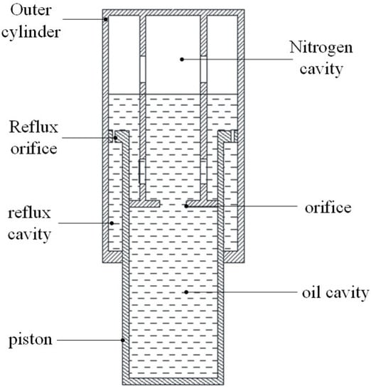
Figure 1.
Schematic diagram of the oleo-pneumatic shock absorber structure.
2.2. Oil Damping Force
In the process of the shock absorber movement, the internal oil flowing through the oil orifice creates a problem of orifice outflow. Figure 2 shows a schematic diagram of oil outflow. It can be seen in the figure that the oil flows uniformly before reaching the orifice. Near the orifice, the oil flow section becomes narrow, the oil contracts, and the flow rate increases. The oil flow velocity reaches its maximum when the oil enters the orifice. When the oil outflow orifice reaches the c-c section, the oil flow bundle begins to expand continuously, and then the flow rate decreases, and a steady flow is restored. Since there was no oil and gas mixing at the orifice during the numerical simulation, a calculation model of oil damping force could be deduced according to the relevant theories of engineering fluid mechanics.
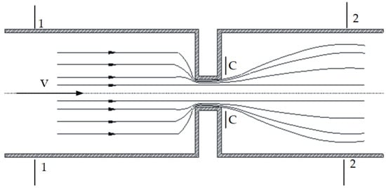
Figure 2.
Schematic diagram of the outlet flow.
For sections 1-1, 2-2 of Figure 2, according to Bernoulli equation, the following equation were obtained:
where, , are the pressure in the 1-1 and c-c sections, , are the average flow velocity in the 1-1 and c-c sections, respectively, is the oil density, and is the local flow discharge coefficient of the orifice.
According to the continuity equation, the following equation was obtained:
where , are the cross-sectional areas of the 1-1 and c-c sections, respectively, and are the shrinkage coefficients.
By combining the continuity equation and the Bernoulli equation, the expressions of flow velocity and orifice flow coefficient in the contraction section were obtained as follows:
where is the velocity coefficient.
The expression of the orifice flow is:
where is the oil orifice flow rate, is the oil orifice area, and is the damping orifice flow coefficient.
Finally, the damping force calculation formula could be deduced [11]:
where is the oil damping force, is the pressure difference between two sides of the oil orifice, is the effective oil pressure area, and is the piston rod compression speed.
3. Model Design and Grid Division
Considering the complexity of the shock absorber, the model was simplified appropriately. In this paper, the influence of the main oil orifice on the flow field characteristics was studied; therefore, the structure of the reflux orifice was simplified. Considering the symmetry of the model, as well as the accuracy and time of the solution, a quarter of the model was selected for meshing. In the shock absorber model studied in this paper, grid encryption was needed to improve the calculation accuracy because of the drastic changes in the flow field near the orifice. The grid model is shown in Figure 3:
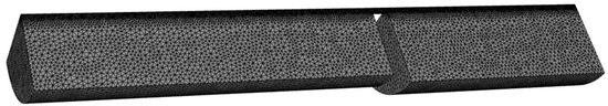
Figure 3.
D mesh model of the shock absorber.
For the numerical simulation, the number of independent mesh cells should be determined for different models [12], In order to study the relationship between the grid density and the calculation results and eliminate the interference of the mesh number on the calculation results in the subsequent calculation, this study gridded the same shock absorber model according to different mesh densities. Table 1 shows the calculation results of the oil damping force under the same compression speed for different mesh cell density models.

Table 1.
Mesh independent test.
As can be seen in the table, when the number of grids was small, the calculation results fluctuated greatly, and there was a large residual. With the increasing of the number of grids, the calculation results tended to be stable. However, when the density of the mesh reached a certain level, the continuous increase in the number of grids had a little effect on the calculation results. At the same time, since the remeshing method was used in the dynamic mesh, an excessive number of grids would greatly affect the computational efficiency, so an appropriate number of grids should be selected. In this paper, the selected number of grids was 85,000.
4. Numerical Simulation and Experimental Design of a Two-Phase Flow
4.1. Conservation Equation for the Numerical Simulation of a Two-Phase Flow
In this paper, a gas–liquid two-phase flow was used to simulate the buffer. The compressibility of nitrogen was not considered. For a gas–liquid two-phase flow with a compressible phase, the relevant conservation equation is as follows:
where is the density, is the velocity, is the second viscosity, is the identity matrix, is the pressure, is the gravitational acceleration, is the hydrodynamic viscosity, is the surface tension.
The energy conservation equation is
where is the fluid temperature, is the fluid velocity, is the fluid heat conduction coefficient, and is the energy source.
4.2. VOF Method
In the simulation of a gas–liquid two-phase flow in the shock absorber, there is an interface between hydraulic oil and nitrogen in the initial stage. For such problems with an obvious initial interface, the VOF method is usually employed [13]. The VOF model constructs and tracks the free interface by introducing the volume fraction a of each phase fluid in the grid cell at each time. The free interface is reconstructed by solving the following equation:
In the calculation of the VOF model, the sum of the volume fractions of all phases in the cell is defined as 1. For the oil–gas buffer, the nitrogen volume fraction is , and the oil volume fraction is . That is, the following happens in the cell:
where means that the unit is filled with nitrogen, indicates that both nitrogen and oil exist in the unit, and indicates that the unit is full of oil.
The density and viscosity of the fluid are calculated according to the following equation:
where and are the density of nitrogen and oil, and are the viscosity of nitrogen and oil.
According to the VOF modeling, nitrogen was set as the first phase and defined as a compressible fluid. Oil was the second phase and was defined as an incompressible fluid. Figure 4 shows the schematic diagram of the VOF.
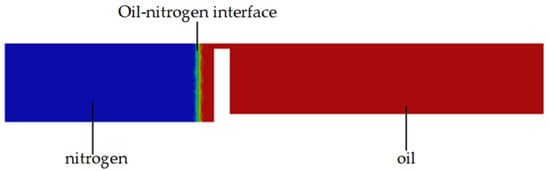
Figure 4.
Schematic of the VOF.
4.3. Boundary Conditions and Solution Settings
In the process of shock absorber compression, the oil cavity and the nitrogen cavity are compressed. Therefore, the dynamic mesh technology was adopted to simulate the shock absorber compression process by writing the UDF program to control the boundary motion [14]. Table 2 shows the UDF control functions. The motion of Moving-wall1 and Moving-wall2 was controlled by this function. The smoothing and remeshing in a dynamic mesh can guarantee the quality of the mesh in motion. Table 3 shows the settings of the initial conditions related to CFD. Figure 5 shows the schematic diagram of the boundary conditions.
Table 2.
Boundary motion function.
Table 3.
CFD model properties.
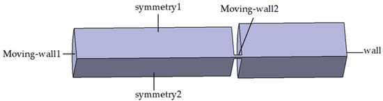
Figure 5.
Schematic diagram of the boundary conditions.
4.4. Shock Absorber Parameters Design
In this paper, the single factor control variable method was used to study the influence of different oil orifice parameters on the flow field characteristics of the shock absorber during compression. The specific parameters are shown in Table 4. This paper conducted a numerical simulation according to the following parameters of the shock absorber.
Table 4.
Shock absorber parameters.
5. Analysis of the Numerical Simulation Results
In order to study the characteristics of the two-phase flow inside the shock absorber, the orifice length was 15 mm, the diameter was 10 mm, and the compression speed was 0.4 m/s for the simulation calculations. The overall calculation time was 0.125 s. Equation (5) is commonly used to estimate the oil damping force of the shock absorber in engineering. The main core of engineering damping force calculation is to determine the orifice flow coefficient. The damping coefficient of the oil orifice is usually an engineering value determined by the landing gear drop shock test. Then, it is convenient to estimate the oil damping force when the shock absorber is designed. Based on pipeline hydrodynamics and the damping orifice structure, Ding [15] established a flow coefficient model of the oil orifice and carried out a numerical calculation. When the flow coefficient of the oil orifice is 0.79, the calculated damping force is closer to the experimental result. At the same time, this method also improves the accuracy of the estimation of the engineering oil damping force. Therefore, in this paper, the flow coefficient of the oil orifice was set to s 0.8 ( = 0.8) to calculate the engineering oil damping force. Figure 6 shows the comparison between the engineering estimation results and the numerical simulation results of the shock absorber oil damping force. It can be seen from the figure that the simulation values were basically larger than the engineering estimation results, with an overall error between 7 and 8%. Therefore, it was reasonable to use the numerical simulation results to analyze the performance of the shock absorber.
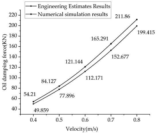
Figure 6.
Comparison of simulation results and engineering estimation results at different compression velocities.
Figure 7 shows the oil volume fraction contour of the shock absorber at 0 s, 0.025 s, 0.05 s, 0.075 s, 0.1 s and 0.125 s, respectively. As can be seen in the figure, there was an obvious gas–liquid interface before the shock absorber worked. As the piston compressed, the oil flowed through the oil orifice at a high speed; the oil was mainly in the form of a jet. The oil jet hit the upper wall and then flowed downward attached to the upper wall and mixed with nitrogen. As you can see, the nitrogen eventually became compressed into a mass.
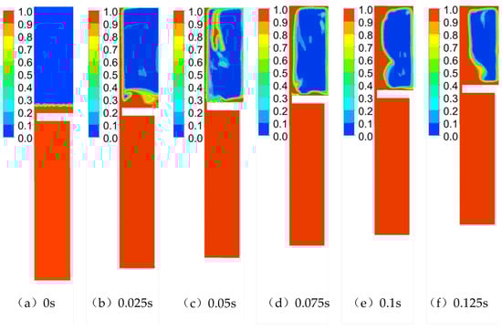
Figure 7.
Contour of the shock absorber oil volume fraction over time.
Figure 8 shows the pressure, velocity temperature contour of the shock absorber at 0.125 s. It can be seen from the figure that the oil flowed through the orifice. Due to the throttling effect of the orifice, the oil velocity was large at the orifice and then slowly attenuated with continuous upward injection. In the working process of the shock absorber, the pressure of the oil chamber and of the gas chamber continued to increase, and nitrogen was compressed to absorb a large amount of heat. It can be seen from the temperature contour that the highest temperature was concentrated in the nitrogen center.
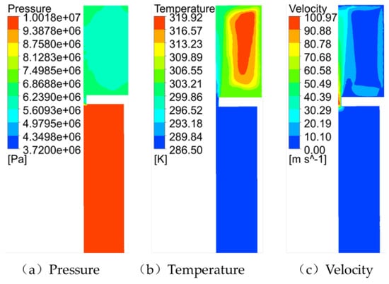
Figure 8.
Contour of results when the orifice length was 15 mm and the diameter was 10 mm.
5.1. Effect of the Orifice Length on the Shock Absorber Performance
In order to study the effect of the orifice length on the shock absorber, the diameter of orifice was controlled to be 10 mm, the compression speed was 0.4 m/s, and the calculation time was 0.125 s. The orifice length was changed to 5 mm, 10 mm, 15 mm, 20 mm and 25 mm, respectively, for the calculation.
Figure 9 shows the oil volume fraction contour inside the shock absorber with different orifice lengths. It can be seen that with different orifice lengths, the gas–liquid distribution was different. As the orifice length increased, the flow field of the two-phase flow became more chaotic, but the overall trend was the same: nitrogen was compressed in the middle of the upper cavity.
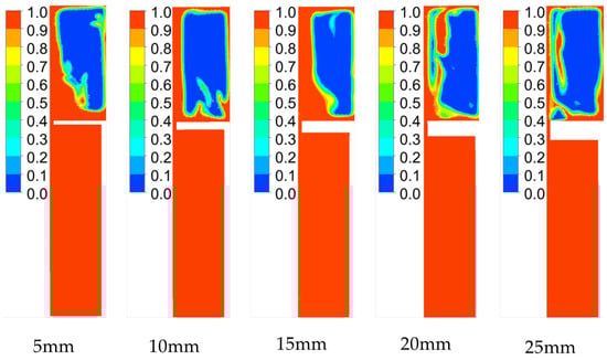
Figure 9.
Contour of oil volume fraction inside the shock absorber with different orifice lengths.
Figure 10 shows the numerical simulation results of the shock absorber with different orifice lengths. Figure 10a shows the speed variation diagram of the orifice for different orifice lengths. It can be seen that, as the orifice length gradually increased, the maximum speed in the shock absorber first increased and then decreased, but the overall change was relatively small, and the maximum speed was reached when the orifice length was 10 mm. Figure 10b shows the variation of the maximum temperature inside the shock absorber under different orifice lengths. It can be seen that the temperature variation first decreased and then increased with different orifice lengths. When the orifice length was 15 mm, the nitrogen temperature was the lowest. Figure 10c shows the variation of the maximum pressure inside the shock absorber for different orifice lengths. It can be seen that the maximum pressure increased first and then decreased with the increase of the orifice length, and the variation range was small. Figure 10d shows the variation of the oil damping force of the orifice for different orifice lengths. It can be seen that the orifice length increased, but the oil damping force decreased slowly and tended to be flat when the orifice length was larger than 15 mm. It can be seen that the increase in the orifice length had a certain impact on the shock absorber performance, but the impact was small.
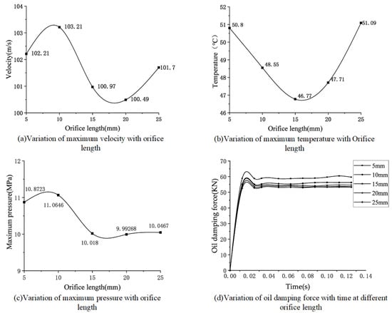
Figure 10.
Results of the numerical calculation for different orifice lengths.
5.2. Effect of the Orifice Diameter on the Shock Absorber Performance
The length of the control orifice was 15 mm, the compression speed was 0.4 m/s, and the calculation time was 0.125 s. The diameter of the orifice was changed to 10 mm, 13 mm, 16 mm, 19 mm and 22 mm, respectively, for the numerical calculation.
Figure 11 shows the oil volume fraction contour inside the shock absorber for different orifice diameters. It can be seen that, as the diameter increased, the compressed volume of nitrogen decreased, and the oil around the hole increased.
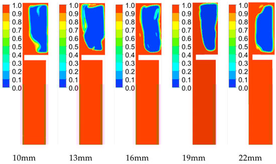
Figure 11.
Contour of oil volume fraction for different orifice diameters.
Figure 12 shows the calculation results of the internal flow field of the shock absorber for different orifice diameters. Figure 12a shows the variation of the maximum velocity inside the shock absorber for different orifice diameters. It can be seen that, as the diameter increased, the maximum velocity inside the shock absorber decreased continuously and finally, as the diameter increased, the velocity decreased gradually. Figure 12b shows the nitrogen maximum temperature inside the shock absorber for different diameters. It can be seen that the maximum temperature increased with the increase of the diameter and finally became increasingly flatter. Figure 12c shows the variation of the maximum pressure inside the shock absorber for different orifice diameters. As the diameter increased, the maximum pressure decreased sharply at the beginning and became flat at the end. Figure 12d shows the variation of the oil damping force for different orifice diameters. It can be seen that, with the increase of the diameter, the oil damping force decreased continuously, with the largest variation for diameters of 10 mm and 13 mm, and the variation range gradually decreased with the increase of the diameter. It can be seen that the orifice diameter had a great influence on the performance of the shock absorber.
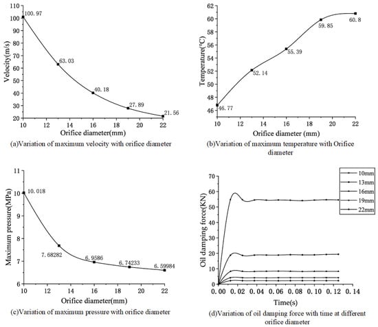
Figure 12.
Numerical calculation results for different diameters.
6. Conclusions
In this paper, an accurate two-phase flow model of an oleo-pneumatic shock absorber was established to simulate the characteristics of an oil–nitrogen two-phase flow in the shock absorber and to study the performance of the shock absorber with variable oil orifice parameters. The following conclusions were drawn through the numerical simulation:
- The results of the oil volume fraction contour showed that the oil flowed out of the damping orifice and mixed with nitrogen mainly in the form of a turbulent jet when the oleo-pneumatic shock absorber was working. When the oil jet hit the upper wall, it fell off the upper wall with gravity. The continuous compression of the nitrogen cavity and oil cavity made the two phases of oil and nitrogen acquire a mutually coiling complex movement, and a large amount of oil moved down along the upper wall. Finally, nitrogen was compressed in the center of the nitrogen cavity. It can be seen from the temperature contour that the middle of the nitrogen chamber had the highest temperature, and the temperature rose to about 25 °C, which indicated that nitrogen absorbed a lot of energy.
- With the increase of the orifice length, the maximum pressure, maximum speed and oil damping force inside the shock absorber decreased; the values of these parameters increased for orifice lengths of 5–15 mm and were basically stable for lengths over 15 mm. The orifice length had a great influence on the internal temperature of the shock absorber, and the maximum temperature was the lowest for a length of 15 mm. From the analysis of the flow angle of the small orifice, it appears that an increase in the hole length will increase the flow time through the small orifice of the oil attached to the small orifice, making the flow rate of the oil more stable; in this way, the damping force and other parameters of the oil will be reduced, but the changes will not be large.
- Increasing the diameter of the oil orifice had a great influence on the performance of the shock absorber. With the increase of the diameter of the oil orifice, the maximum velocity decreased from 100.97 m/s to 21.56 m/s, the maximum pressure decreased from 10 MPa to 6.5 MPa, and the oil damping force decreased from 54.13 KN to 2.28 KN. The temperature decreased as the diameter of the orifice increased. As a whole, the changes were the largest for diameters between 10 mm and 13 mm, and then the values tended to stabilize. It can be seen that the selection of the oil orifice diameter had a great influence on the performance of the shock absorber. This indicates that a too large oil orifice diameter will make a shock absorber lose its damping effect.
Author Contributions
Conceptualization S.D. and K.Z.; methodology, S.D.; software, S.D. and Z.Z.; validation, S.D. and K.Z.; formal analysis, S.D.; investigation, S.D.; resources, C.Z.; data curation, S.D.; writing—original draft preparation, S.D.; writing—review and editing, C.Z. and Z.Z.; supervision, C.Z.; project administration, C.Z.; funding acquisition, C.Z. All authors have read and agreed to the published version of the manuscript.
Funding
This research was funded by Shaanxi Province Qin Chuang Yuan “Landing Gear Performance Test and Equipment Research” Scientists and Engineers Team, grant number 2022KXJ-139; and Key technology and development of five-axis linkage CNC boring and milling machine, grant number 2019ZDLGY01-03.
Data Availability Statement
All data used in this study are declared in the paper.
Conflicts of Interest
The authors declare no conflict of interest.
References
- Yazici, H.; Sever, M. Active control of a non-linear landing gear system having oleo pneumatic shock absorber using robust linear quadratic regulator approach. Proc. Inst. Mech. Eng. Part G J. Aerosp. Eng. 2017, 232, 2397–2411. [Google Scholar] [CrossRef]
- Pecora, R. A Rational Numerical Method for Simulation of Drop-Impact Dynamics of Oleo-Pneumatic Landing Gear. Appl. Sci. 2021, 11, 4136. [Google Scholar] [CrossRef]
- Bharath, M.; Singh, P.; Kantheti, B. Determination of Influence of Parameters on Undercarriage Shock Absorber. SAE Int. J. Aerosp. 2018, 11, 85–114. [Google Scholar] [CrossRef]
- Ding, Y.W.; Zhang, Z.H.; Wei, X.H.; Gan, S.Y. Influence of Orifice Geometry Parameters on Landing Gear Drop Dynamics. Aeronaut. Comput. Tech. 2018, 48, 30–33. [Google Scholar]
- Nie, W.Z.; Lu, J.M.; Ma, Y.J.; Chen, X.D. Analysis on the characteristics of the damping hole of landing gear buffer. Mach. Tool Hydraul. 2021, 49, 151–155. [Google Scholar]
- Heirendt, L.; Liu, H.H.T.; Wang, P. Aircraft Landing Gear Thermo-Tribomechanical Model and Sensitivity Study. J. Aircraft. 2014, 51, 511–519. [Google Scholar] [CrossRef][Green Version]
- Lou, R.; She, S.Q.; Lu, D.F. Oleo-pneumatic mixed shock absorber landing pressure analysis of landing gear. Adv. Aeronaut. Sci. Eng. 2020, 11, 380–386. [Google Scholar]
- Jiao, F.J. Oil damping energy loss analysis of landing gear shock absorber. Proc. Inst. Mech. Eng. Part G J. Aerosp. Eng. 2019, 233, 3096–3109. [Google Scholar] [CrossRef]
- Wu, W.; Tang, H.; Zhang, S. High-Precision Dynamics Characteristic Modeling Method Research considering the Influence Factors of Hydropneumatic Suspension. Shock Vib. 2020, 2020, 8886631. [Google Scholar] [CrossRef]
- Deng, P.Y.; Gu, Z.Q.; Zhang, S.; Ma, X. Research on two-phase flow mechanics properties of hydro-pneumatic suspensions considering physical property varieties. China Mech. Eng. 2017, 17, 2043–2048. [Google Scholar]
- Ahmad, M.A.; Shah, S.I.A.; Shams, T.A.; Javed, A.; Rizvi, S.T.U.I. Comprehensive design of an oleo-pneumatic nose landing gear strut. Proc. Inst. Mech. Eng. Part G J. Aerosp. Eng. 2020, 235, 1605–1622. [Google Scholar] [CrossRef]
- Wang, P.; Lv, J.Z.; Bai, M.L.; Wang, Y.; Hu, C. Numerical investigation of the flow and heat behaviours of an impinging jet. Int. J. Comput. Fluid Dyn. 2014, 28, 301–315. [Google Scholar] [CrossRef]
- Fan, W.; Anglart, H. Progress in Phenomenological Modeling of Turbulence Damping around a Two-Phase Interface. Fluids 2019, 4, 136. [Google Scholar] [CrossRef]
- Saad, M.M.M.; Mohd, S.; Zulkafli, M.F.; Samiran, N.A.; Didane, D.H. CFD Simulation Study on the Performance of a Modified Ram Air Turbine (RAT) for Power Generation in Aircrafts. Fluids 2021, 6, 391. [Google Scholar] [CrossRef]
- Ding, Y.W.; Wei, X.H.; Nie, H.; Nie, H.; Li, Y.P. Discharge coefficient calculation method of landing gear shock absorber and its influence on drop dynamics. J. Vibroeng. 2018, 20, 2550–2562. [Google Scholar] [CrossRef]


Publisher’s Note: MDPI stays neutral with regard to jurisdictional claims in published maps and institutional affiliations. |
© 2022 by the authors. Licensee MDPI, Basel, Switzerland. This article is an open access article distributed under the terms and conditions of the Creative Commons Attribution (CC BY) license (https://creativecommons.org/licenses/by/4.0/).