Review

Recent Advancements in Fish-on-Chip: A Comprehensive Review

by
Tushar Nath
and
Hua Tan
*
School of Engineering and Computer Science, Washington State University-Vancouver, Vancouver, WA 98686, USA
*
Author to whom correspondence should be addressed.
Fluids 2025, 10(4), 88; https://doi.org/10.3390/fluids10040088
Submission received: 16 January 2025 / Revised: 14 March 2025 / Accepted: 27 March 2025 / Published: 31 March 2025

Abstract

:
Zebrafish (Danio rerio) emerged as a suitable vertebrate model organism in the 1960s, owing to its transparent embryos and ease of breeding. Research utilizing zebrafish as a model organism gained significant momentum in the 1970s, particularly in the field of developmental biology. Over the years, zebrafish has become an indispensable model across various domains of biological research. However, conventional techniques for handling zebrafish in research settings have been limited by challenges related to survival rates, throughput, and imaging capabilities. The advancements in microfluidics and Micro-Electro-Mechanical Systems (MEMS) technology have addressed many of these challenges, enabling significant progress in zebrafish-based studies. The integration of microchannels, which ensure laminar flow for precise liquid handling, alongside microsensors and actuators for trapping mechanisms and high-resolution imaging, has greatly enhanced experimental efficiency and precision. This review provides a comprehensive analysis of very recent advancements in Fish-on-Chip (FOC) technologies, with a focus on their applications in zebrafish research, including trapping, imaging, transportation, and studies involving drug screening and disease modeling. Furthermore, we discuss recent efforts in retaining progressively motile zebrafish sperm, which is increasingly critical to meeting the rising demand for diverse zebrafish lines. Finally, we discuss an automated microfluidic-based fish farm developed using these technologies and conclude the review by highlighting potential future directions for Fish-on-Chip (FOC) technology.

1. Introduction

The zebrafish (Danio rerio) has emerged as a pivotal model organism in fields such as chemical biology, disease modeling, drug screening, genetics, neurology, and antibody staining, owing to its distinct advantages [1,2,3,4,5,6,7,8,9]. These include high-throughput screening capabilities, comparable to those of invertebrate models like fruit flies (Drosophila melanogaster) and nematodes (C. elegans) [10,11,12,13,14,15,16]; a short egg-laying period with high fecundity; rapid embryonic development [17,18]; an optically transparent body; and significant genetic similarity to humans (~70%) [19,20]. Initially recognized as a suitable vertebrate model in the 1960s, zebrafish research has advanced from the manual use of agarose gel for positioning under anesthesia [21,22,23,24] to automated trapping and orientation control systems for high-resolution imaging, which has been possible by advancements in microfluidics and Micro-Electro-Mechanical Systems (MEMS) technologies [25,26,27,28,29,30,31,32,33,34,35,36,37,38,39,40,41,42,43,44,45].
The use of microchannels designed for laminar flow ensures minimal mixing of parallel liquid streams, improved flow control, and reduced shear stress on embryos and larvae. Additionally, these systems provide zebrafish with an environment that more closely resembles natural conditions through continuous liquid circulation, overcoming the static constraints of microplates or glass slides [21]. Furthermore, the integration of microsensors, actuators, and high-speed photography has enabled detailed studies of phenotypic and behavioral responses to external stimuli (e.g., electrical, mechanical, hydraulic, visual, sound, and chemical) [46,47,48,49,50,51,52], as well as studies on drug effects, disease mechanisms [53,54,55,56,57], embryonic development [58,59,60,61], microinjection [62,63], and antibody staining [64]. As an added advantage, computer aided engineering (CAE) analysis, renowned for its exceptional capability in modeling stress strain behavior in large mechanical structures [65,66], has emerged as a powerful tool for predicting stress distributions on zebrafish embryos and larvae as well within these microfluidic systems.
As zebrafish becomes increasingly indispensable in biological research, the challenge of maintaining over 20,000 developed zebrafish lines has prompted efforts to improve the storage and restoration of progressively motile zebrafish sperm [67,68,69]. Here, microfluidics and MEMS technologies also play a critical role in advancing sperm storage and retention techniques [70,71].
The various research areas involving zebrafish as a vertebrate model are closely interconnected. For instance, conducting comprehensive studies on diseases, drug screening, or neurology often requires suitable platforms to observe detailed phenotypic responses to different stimuli. This, in turn, necessitates effective methods for trapping and orientation control of larvae to enable high-quality imaging, along with systems that ensure precise control of stimuli throughout experiments, all while minimizing stress or morphological abnormalities in the larvae. Additionally, understanding disease mechanisms demands advanced microinjection techniques for the targeted delivery of drugs or cells to specific organs or body parts of zebrafish. Moreover, to support these extensive research needs, it is crucial to have an abundant supply of zebrafish, which highlights the importance of efficient techniques for the storage and activation of sperm from various zebrafish lines. Figure 1 illustrates the interconnections between these research areas as discussed.
In recent years, significant advancements have been made across all the interconnected research fields mentioned above. Progress in one area has often facilitated developments in others, creating a synergistic impact that has driven innovation and expanded the possibilities of zebrafish-based studies. This review aims to provide a comprehensive analysis of those advancements in zebrafish research enabled by microfluidics and MEMS technologies. The works are categorized into relevant sections for clarity:
  • Section 2: Automated capture and culturing of zebrafish embryos.
  • Section 3: High-resolution and advanced imaging techniques.
  • Section 4: Novel techniques in drug and disease studies.
  • Section 5: Novel stimulation and transportation methods.
  • Section 6: Microinjection techniques and sperm retention studies.
  • Section 7: Development of a smart microfluidics-based fish farm for zebrafish screening.
Table 1 summarizes these recent advancements in different fields of zebrafish research.
The following sections of the paper provide a detailed discussion of these advancements. The paper concludes with a discussion of future perspectives and potential areas for further innovation in this rapidly evolving field.

2. Automated Capture and Culturing of Zebrafish Embryos

High-quality imaging, non-invasive transportation, and stimulation techniques are fundamental requirements for zebrafish-based research in areas such as disease studies, drug screening, and microinjection. Traditional static microplate-based experiments often fall short of meeting these demands effectively. Conventional experiments with zebrafish embryos using microplates face several limitations, including the accumulation of chemical compounds, cross-contamination among embryo metabolites due to static fluidic environments, and discrepancies between natural fluid conditions and those within microplates [21,22,23,24]. Additionally, challenges such as suboptimal live imaging quality, caused by the movement of embryos, further hinder their utility [87]. To address these issues, the development of microfluidic devices has been a significant focus in recent years [58,59,60,61]. These devices offer low-cost fabrication, facilitate optimal embryo trapping for high-quality imaging, and enable behavioral and other studies while minimizing shear stress induced on the embryos.
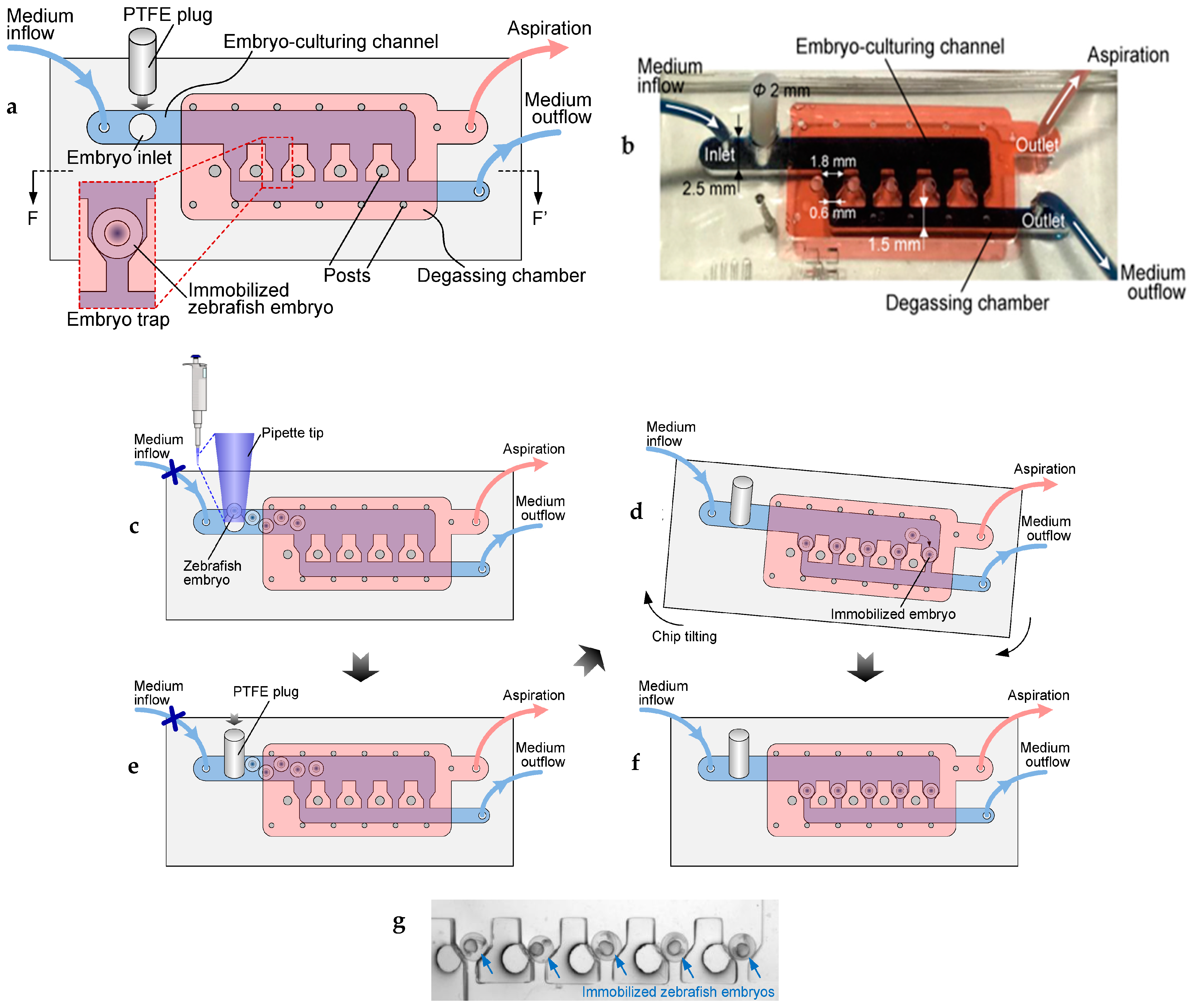
Zhu et al. [58,59] introduced a microfluidic device capable of gentle immobilization, perfusion, stable culturing, and high-resolution imaging of zebrafish embryos with minimal shear stress. This device consists of two layers of polydimethylsiloxane (PDMS) bonded to a glass substrate (Figure 2a,b). The top PDMS layer incorporates a degassing chamber designed to remove air bubbles from the bottom fluidic channel through vacuum application. The bottom PDMS layer houses an embryo culturing channel with five traps specifically designed to load and capture embryos. Embryos are introduced through an inlet using a pipette, after which the device is tilted manually to roll and dock the embryos into the traps one by one (Figure 2c–f). The device’s performance was evaluated using long-term embryo culturing and time-lapse imaging of embryonic development (Figure 2g), demonstrating its efficacy in supporting advanced imaging and culturing needs.
Chen et al. [60] proposed a novel on-chip platform designed to automatically and efficiently trap and rotate zebrafish embryos using a low-cost 3D-printed microchannel system. The design incorporates cavity arrays that trap embryos, with each cavity featuring a blind-hole structure capable of generating microbubbles. These bubbles, when exposed to acoustic waves of specific frequencies, facilitate the trapping and rotation of embryos. The system is fully automated and monitored using computer vision, achieving a trapping success rate of 99% with an average trapping time as low as 0.2 s per embryo.
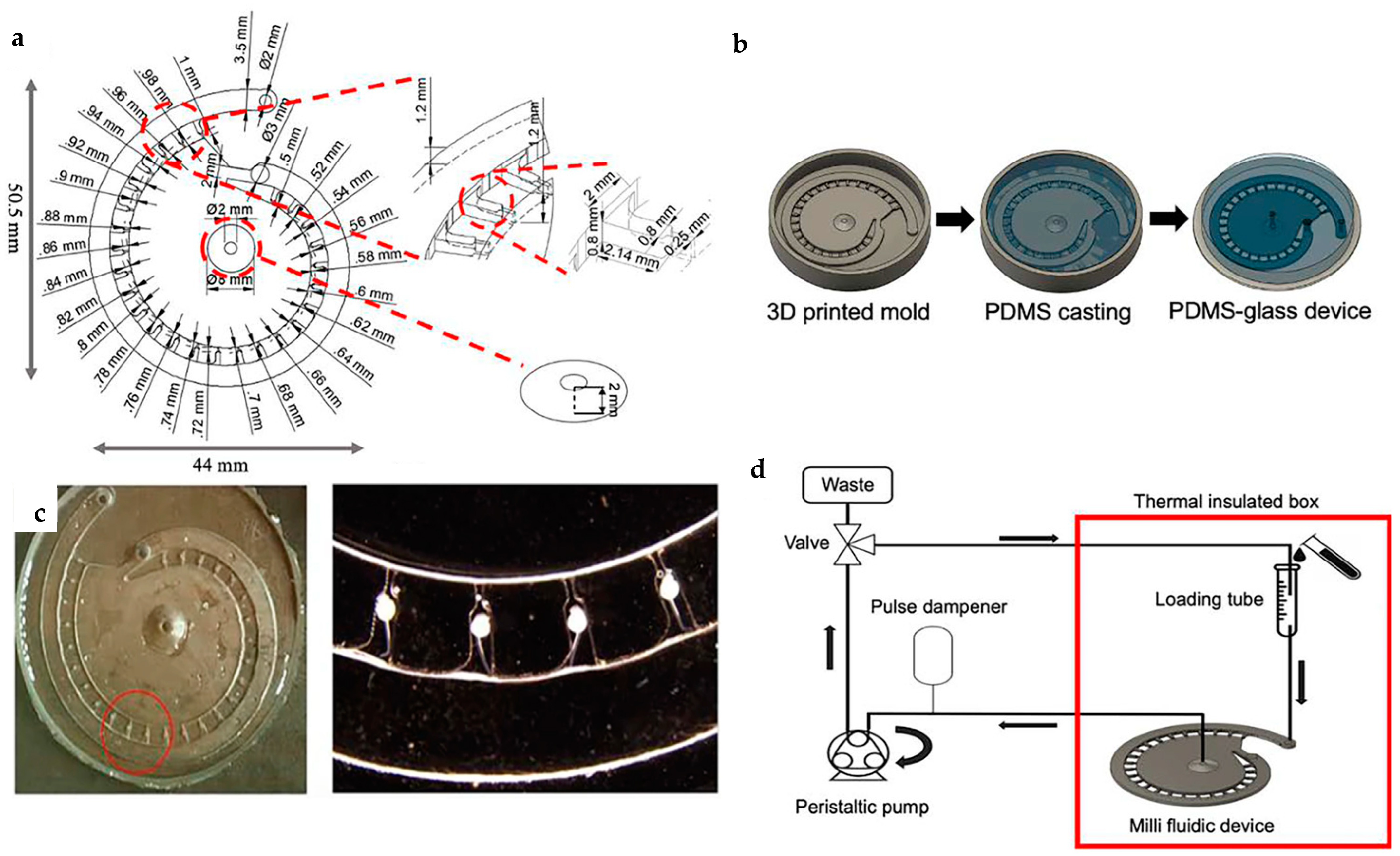
Ye et al. [64] developed a milli fluidic device specifically for the automatic trapping and immobilization of chorion-less zebrafish embryos for whole-mount antibody staining (ABS) and in situ hybridization (ISH). This cost-effective device fabricated by PDMS casting (Figure 3b) comprises three primary functional components: a spiral main channel, an inner suction chamber, and 26 trapping channels interconnecting the main channel and an inner reservoir (Figure 3a). The device employs hydrodynamic suction as the primary trapping and immobilization mechanism, with the inner suction chamber connected to a peristaltic pump at the outlet to generate negative pressure (Figure 3d). This design ensures fluid flow through the traps, enabling efficient embryo capture (Figure 3c). The multi-depth architecture of the traps and channels minimizes mass transfer distances, prevents bubble entry, and facilitates the release of bubbles accumulating in the reservoir. While the device has been proven effective for trapping chorion less embryos, follow-up experiments are required to evaluate its performance with embryos possessing intact chorions and refine the design as necessary.
High-throughput screening (HTS) has become a cornerstone technique for performing a wide range of biochemical, phenotypic, and genetic experiments in parallel. Traditionally, HTS relies on the use of microtiter plates, which have evolved over the past several decades from formats with six wells to as many as 3072 wells per plate [88,89]. With the growing demand for high-throughput entrapment and screening of zebrafish embryos, the development of platforms that enable rapid entrapment and screening with minimal manual intervention has become essential. Popova et al. [61] introduced a novel miniaturized system, the droplet-microarray (DMA) chip, specifically designed for zebrafish embryo screening. The DMA chip leverages an innovative design featuring arrays of highly hydrophilic spots separated by superhydrophobic barriers. This combination of contrasting surface properties in precise micropatterns induces a phenomenon known as discontinuous dewetting. Discontinuous dewetting facilitates pipetting-free formation of nano- to microliter-sized droplets on the hydrophilic spots by simply rolling a source droplet across the patterned surface (Figure 4a).
The viability of zebrafish embryos on the DMA platform was assessed and found to be 88.1% at 48 h post-fertilization (hpf), compared to 91.8% on traditional Petri dishes, demonstrating its suitability for biological studies. The compatibility of the DMA platform for miniaturized toxicity screening was also evaluated. Zebrafish embryos at 24 hpf were distributed onto the DMA chip and exposed to varying concentrations of ZnCl2 and AgNO3 using a sandwich approach (Figure 4b,c). The entire DMA chip was subsequently imaged using either a microscope or a mobile phone camera, and embryo viability was determined by visual inspection (Figure 4d,e). The dose-dependent response to both compounds obtained on DMA platforms was in full agreement with that obtained in 96-well plate (Figure 4f). The DMA platform represents a significant advancement in high-throughput zebrafish embryo screening by offering an efficient, pipetting-free approach to droplet formation, thereby minimizing manual intervention and laborious activity. This technology provides a valuable solution for applications requiring large-scale screening while maintaining high precision and efficiency.
Overall, these advancements discussed above represent a significant step toward automating zebrafish embryo research, improving experimental accuracy, and reducing manual effort in high-throughput applications.

3. High-Resolution and Advanced Imaging Techniques

High-quality imaging has been a top priority in zebrafish research, as it serves as a foundation for advancements in drug screening, neurological studies, microinjection, and other interconnected fields. Unlike microscopic imaging of cells [90,91,92], imaging zebrafish presents unique challenges, including random larval movements, difficulties in achieving desired orientation, the relatively bulky body of zebrafish larvae, and the lack of methodologies for simultaneous observation of multiple organs from different perspectives. Recent advancements have addressed these challenges with innovations such as improved orientation control, simultaneous imaging from multiple angles, and three-dimensional (3D) imaging using advanced techniques like light sheet microscopy [72,73,74,75,76,77,78,79,93].
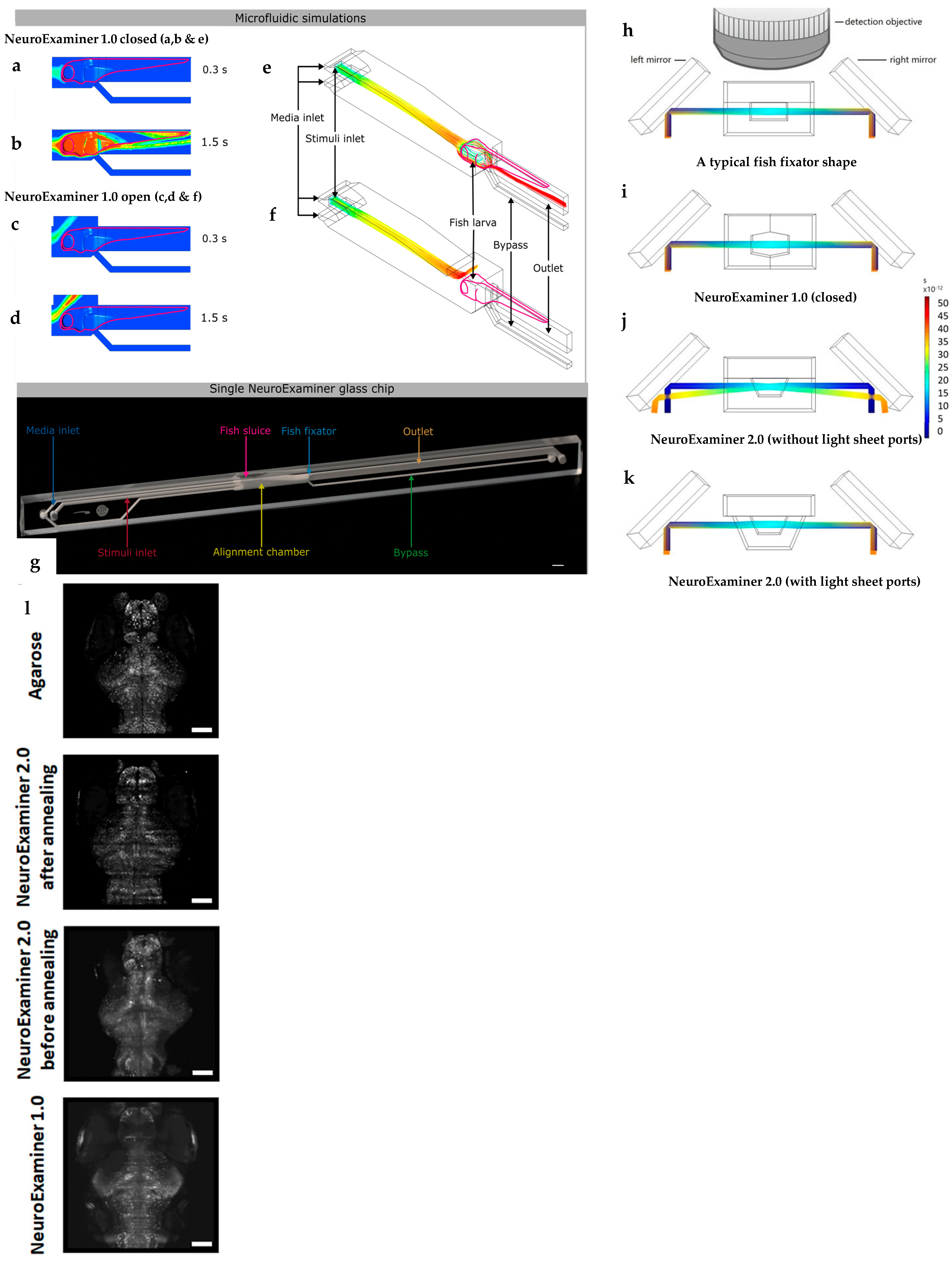
Mattern et al. [72] introduced NeuroExaminer 1.0, an all-glass microfluidic device designed for whole-brain in vivo imaging of zebrafish embryos under chemical stimulation. By replacing polydimethylsiloxane (PDMS) with glass, the device leveraged glass’s superior transparency and reduced autofluorescence, making it particularly suitable for light sheet microscopy. Two variants of the device were developed: partially open and closed systems (Figure 5a–g). The partially open variant enabled single-cell resolution imaging throughout the brain, while the closed variant, although limited to half-brain depth imaging, offered superior control over stimuli exposure and precise time-resolved compound delivery. However, the closed variant’s design limitations in optical path and stimuli regulation necessitated further improvement.
To address these limitations, Schrödter et al. [73] proposed NeuroExaminer 2.0, which introduced significant design enhancements. A plane-parallel glass lid replaced the pointed roof structure in the closed variant, improving light transmission and fluorescence detection (Figure 5h–k). Thermal annealing ensured smoother inner surfaces, creating a near-perfectly clear chamber. Figure 5l shows a comparison between imaging quality in terms of maximum intensity projection of light sheet images of 21 optical sections of zebrafish larvae (5 dpf) expressing nuclear-localized GCaMP6s in the nervous system obtained after embedding in agarose or using one of the three different NeuroExaminer designs (as indicated). The upgraded system allowed precise stimulus delivery to specific regions of the larva’s brain, enabling targeted odor-evoked responses in the left or right olfactory pit. NeuroExaminer 2.0 demonstrated potential for drug testing and research on neuropsychiatric disorders, including anxiety, depression, and addiction. Despite its advanced functionality, the fabrication of both devices required precise microfabrication techniques, rendering them more complex than traditional PDMS-based systems [93].
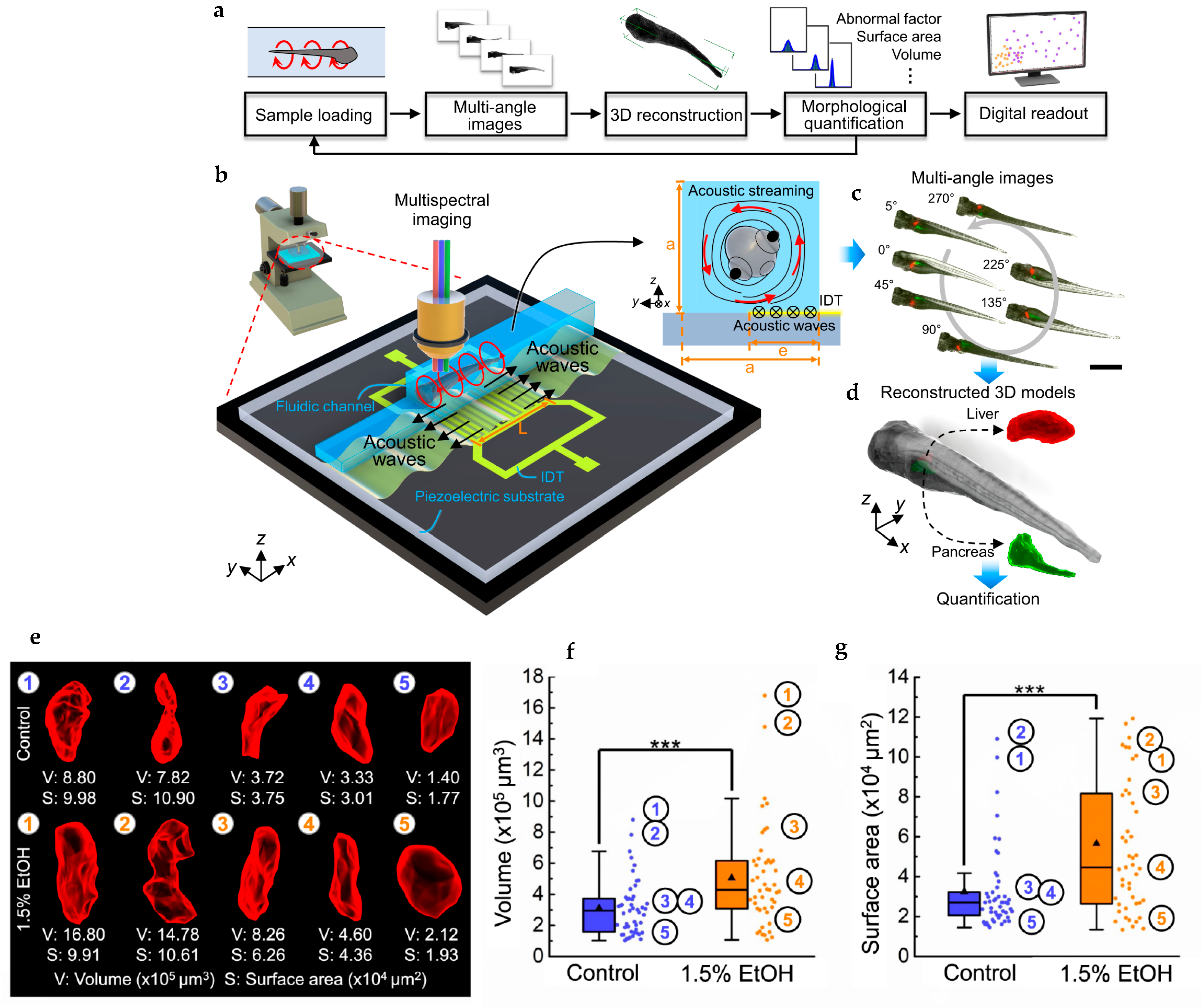
Chen et al. [74] employed an acoustofluidic rotational tweezing (ART) method for high-speed, contactless 3D multispectral imaging and digital reconstruction of zebrafish larvae (Figure 6a). Using an acoustofluidic chip with an interdigitated transducer (IDT) fabricated on a lithium niobate substrate, acoustic waves generated single-vortex acoustic streaming for larval rotation (Figure 6b). This method captured multiple 2D images from various angles (Figure 6c), which were subsequently reconstructed into 3D models using computer vision algorithms for phenotypic analysis (Figure 6d). This system provided a highly efficient and automated approach to analyze morphological features quantitatively. As a validation approach, they utilized the system to study the morphological changes in the liver of zebrafish larvae such as enlarged size and surface roughness under the influence of 1.5% EtOH (Figure 6e–g).
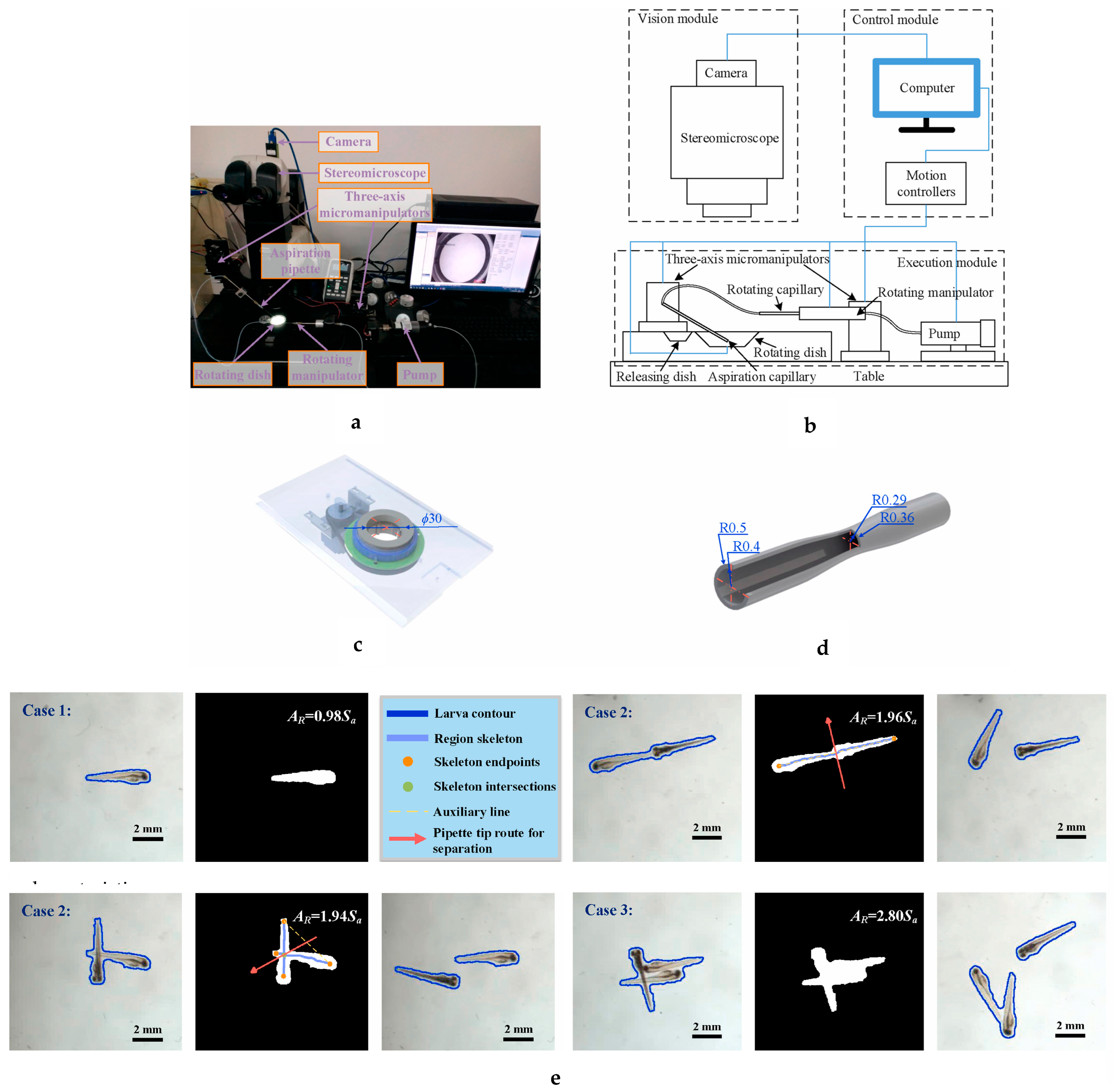
Zhang et al. [75] proposed an advanced high-throughput imaging system (as illustrated in Figure 7a,b) for zebrafish larvae, incorporating functionalities for loading, positioning, rotation, and imaging. The system employs a novel method to distinguish aggregated larvae from single larvae by binarizing captured images of larvae (Figure 7e) within a rotating dish, which forms a part of the execution module. Aggregated larvae are subsequently separated using either an aspiration pipette or a water stream. The rotating dish (Figure 7c), designed to replace traditional Petri dishes, ensures proper orientation of the targeted larva, facilitating its aspiration into the pipette with the tail positioned forward. The system determines the area of a single larva from the binary image and applies an uncertainty factor to accurately separate aggregated larvae from single larvae. For cases involving three or more aggregated larvae, determining their relative positions becomes computationally complex due to the numerous possibilities. Consequently, these larvae are processed last to maintain operational efficiency. To prevent damage, fast-moving larvae are decelerated as they approach the narrow-restricted portion of a specially designed rotating capillary (Figure 7d) used for trapping and imaging. The system also incorporates an algorithm to estimate the rotation angle of the larva within the capillary. This estimation is based on the width of the larva’s two eyes, allowing the calculation of the angle error. The system then adjusts the larva’s position, enabling precise automated rotation to achieve the desired orientation. The system’s functionality was validated using heart rate monitoring experiments, achieving a 100% success rate. This underscores its efficiency and reliability for high-throughput zebrafish imaging applications. The first two techniques (separation of aggregated larvae and decelerating the larvae to prevent damage inside the capillary) focus on enhancing system reliability, while the third (automated orientation control) emphasizes automation and efficiency. Although the control algorithm to decelerate the larva causes a decrease in efficiency compared with the traditional study [94], it ensures better viability of the larvae. Also, the orienting process requires less time than the traditional approach (3.2 s against 5.6 s per larva). Most importantly, this study fills the gap of unavailability of technique for automated separation and loading of either anesthetized or unanesthetized larvae.
Mani et al. [76] developed a zebrafish control scheme (Figure 8a) using the artificial cilia actuation concept that incorporated a moving wall design facilitated by the deflection of shape memory alloy (SMA) wire controlled using electrical waveforms with high accuracy. This system can accommodate zebrafish inside the microchannel from 1-day post-fertilization (dpf) to 6 dpf and can be further extended to 9 dpf for axial orientation control within a rotational range of 0 to 25 degrees at a minimum 2-degree interval. The SMA wire was bent into an arc shape and actuated using an external magnetic coil system to achieve the required deflection. To demonstrate and pre-validate the stepwise rotation of zebrafish larvae in an axial manner through artificial cilia actuation, an experiment was conducted using a PDMS cylinder that mimics the shape of the zebrafish (as shown in Figure 8b). The cylinder was aligned and centered in the microchannel by applying negative pressure through the output tubing. The stepwise axial rotation of the cylinder was performed through direct contact between the cylinder and artificial cilia via the tilting action of the artificial cilia relative to the microchannel’s bottom wall. For larvae aged between 1 dpf and 3 dpf, the relative rotation corresponding to the artificial cilia tilting displayed a linear trend without activating the moving wall structure. However, with the advent of age (i.e., >3 dpf), non-linearity emerged in the relative rotation. Activation of the moving wall helped maintain the linear trend in these cases. This observation can be explained by the changes in the zebrafish body shape as it matures. Specifically, the width of the zebrafish decreases as the yolk shrinks and the body elongates towards the tail. Consequently, the symmetric hypothesis, which assumes the zebrafish body shape is comparable to the cylindrical shape, no longer holds true in these cases.
Subendran et al. [77] also utilized SMA-based actuators in their microfluidic device to immobilize zebrafish within an observation chamber. The SMA coils acted as springs, regaining their preprogrammed shape upon temperature changes and generating the necessary force for immobilization (Figure 8c). The system enabled hydrodynamic quantification of larval tail-beating behavior, facilitating studies on the impact of food additive exposure.
Khalili et al. [78] introduced a device capable of simultaneous lateral and dorsal imaging of zebrafish larvae, addressing a critical need for comprehensive biological studies. The device incorporated a right-angle prism for side imaging, alongside standard dorsal imaging, and utilized a PDMS membrane as a valve for larval trapping. An additional PDMS layer compensated for focal length differences between lateral and dorsal optical paths. To enhance screening efficiency, the team designed an upgraded version [79] accommodating four larvae for simultaneous lateral and dorsal imaging. This system was validated by assessing the effects of ethanol on heart rate and fin beat frequency.
These advancements in zebrafish imaging systems represent significant progress in addressing the limitations of traditional methods. The integration of innovative microfluidic designs, advanced optical systems, and precise manipulation technologies offers powerful tools for high-quality imaging and comprehensive phenotypic analysis in zebrafish research.

4. Novel Techniques in Drug and Disease Studies

Over the years, zebrafish has become a cornerstone in drug discovery and disease study [95,96]. Many drug treatments currently in clinical use or undergoing clinical trials trace their origins to research conducted with zebrafish. Humans and zebrafish share significant similarities in disease-related proteins and biological processes. This similarity allows many drugs that are effective in humans to target equivalent proteins in zebrafish, particularly when interacting with the active sites of these protein [97,98,99]. While certain drugs are effective in humans but not in zebrafish, and vice versa, over two decades of zebrafish drug screening have shown that, overall, compounds active in zebrafish display quite similar efficacy in mice and humans, along with comparable drug metabolism and distribution properties [100]. As discussed in earlier sections, advancements in zebrafish trapping, orientation control, and imaging are opening new avenues for drug and disease research. Hence, the popularity of this animal model is rising continuously in this field. The progress in the Fish-on-Chip (FOC) technology is undoubtedly emerging as a blessing in this regard. In recent years, a variety of innovative microfluidic devices and technologies have been developed, bringing new perspectives and advancements to this field.
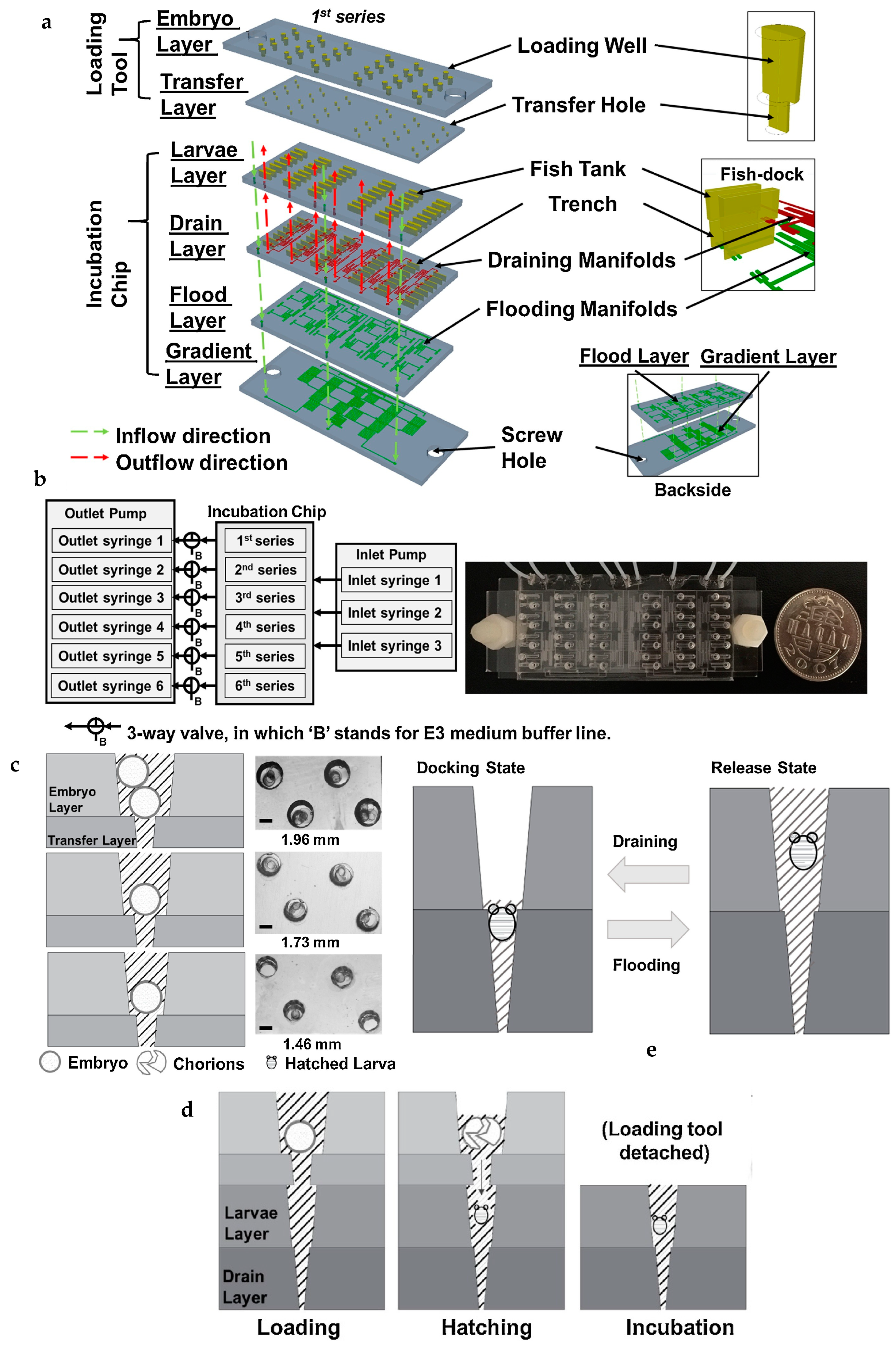
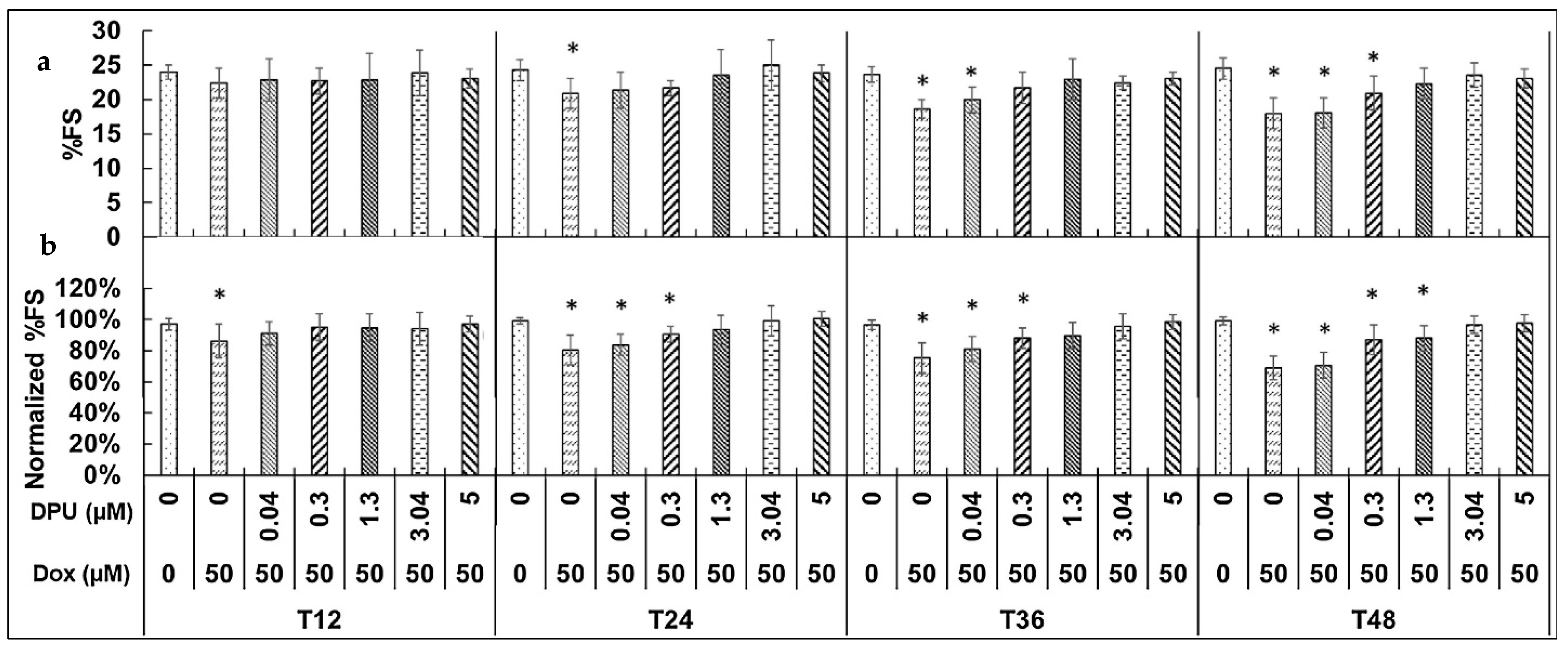
Yu et al. [53] introduced a scalable fish-dock microarchitecture (Figure 9) designed to facilitate time course studies of cardiac responses in individual zebrafish, a capability that is typically infeasible in conventional methods where fishes are sacrificed at discrete time points. By enabling the repeated docking of the same zebrafish at multiple intervals, this microchip allowed for parallel monitoring of cardiac function across 48 individual larvae in time course experiments lasting over 48 h. When compared to traditional analysis methods, time course-normalized single-larva analyses using this device revealed a similar dose dependence of diphenylurea (DPU) in mitigating doxorubicin (Dox)-induced cardiomyopathy. Notably, the drug treatment time required to observe this effect was reduced by half relative to conventional approaches. The device design comprised six individual layers, six outlet syringes, and three inlet syringes (Figure 9a,b), addressing three key challenges associated with conventional on-chip high-throughput larval screening methods. First, the device enabled rapid loading of embryos into designated microstructures (one embryo per microstructure) with minimal manual intervention, eliminating the risk of fungal contamination that typically arises from residual chorions left in the conventional systems post-hatching [28,101]. This was achieved through a detachable loading tool and the optimization of chamber dimensions to accommodate only one embryo per chamber (Figure 9c,d). Second, the chamber geometry was refined to ensure a longer survival period for the larvae while minimizing any adverse effects on their shape or other physical parameters. Third, to maintain the larvae in a consistent orientation during imaging, the design employed a technique akin to a dry dock for ships, whereby water is drained to hold the ship stationary (Figure 9e). This ensured precise and reliable imaging of the larvae. Using this innovative approach, the device was employed to assess the time-dependent effects of Dox, both in the presence and absence of DPU, on the cardiac function of zebrafish larvae. Dox, being widely used in cancer treatment has been reported to cause cardiotoxicity even at low doses and can lead to heart failure with prolonged use. DPU, on the other hand, has been shown to mitigate this adverse effect of Dox without compromising its anticancer effectiveness. To assess myocardial contractility, percent fractional shortening (%FS) was selected as the metric for analysis, as it provides a ratio-metric measurement that accounts for the variability in cardiac sizes among zebrafish within a population. The quantitative results of %FS in Dox-treated larvae at various DPU doses, along with the time course normalization of these results, are presented in Figure 10a and Figure 10b, respectively. Here, 96 hpf larvae were investigated at 12-h intervals as indicated by T12, T24 etc. Time course normalization enables dose dependence to be identified within 24 h (T24) instead of 48 h (T48) by analyzing drug responses in the same zebrafish at multiple time points. This approach minimizes individual variability in drug sensitivity, allowing for more precise correlations and earlier detection of intrinsic dose responses. By comparing results across time points, more treatment groups show significant differences from controls, making this method a more efficient and accurate strategy for drug screening while reducing the required treatment duration.
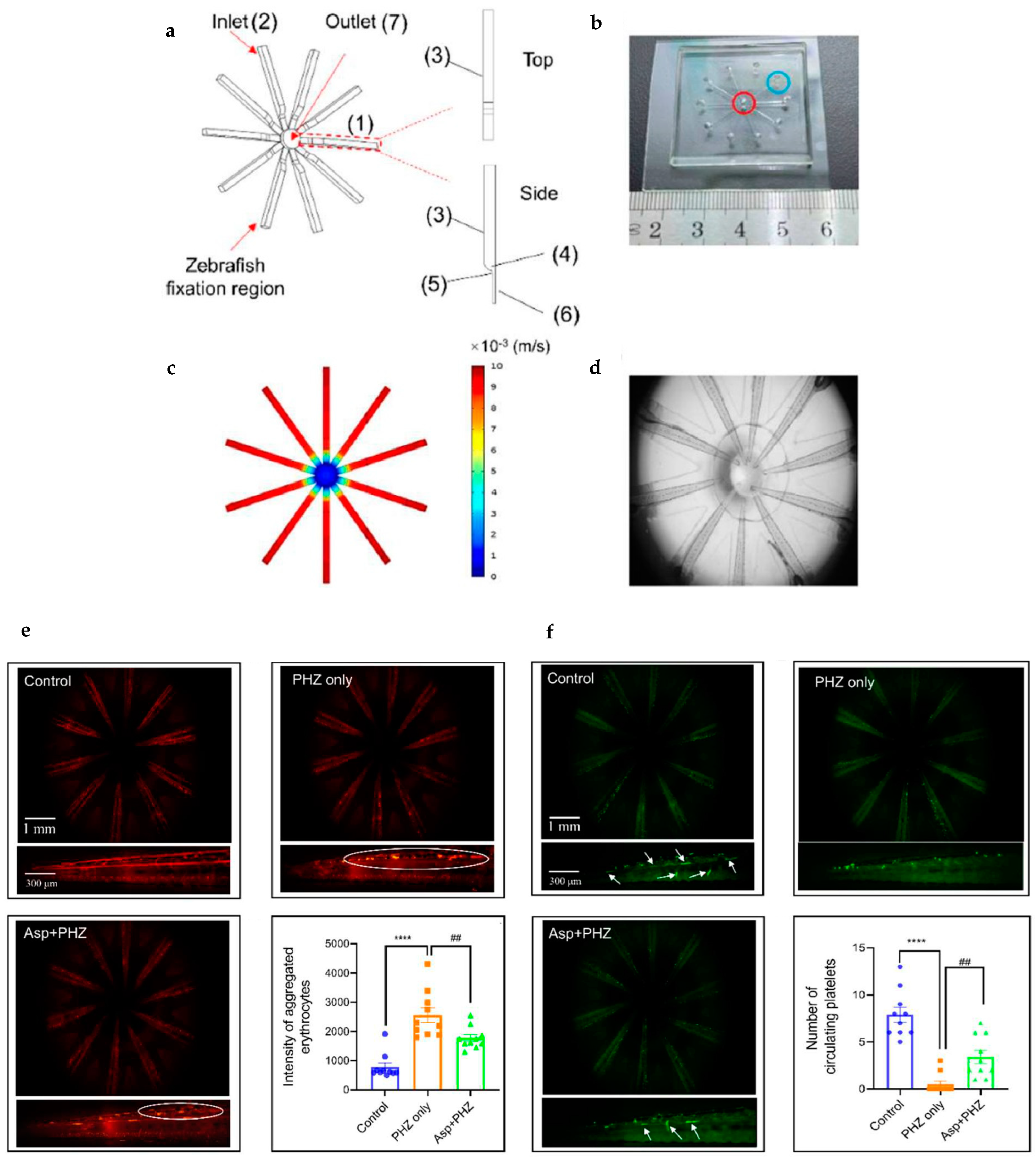
He et al. [54] developed a microfluidic chip designed for the lateral immobilization of zebrafish larvae to facilitate real-time studies of antithrombotic agents. Thrombosis, a significant global health concern, necessitates the development of effective treatments, making zebrafish a valuable model for such studies [102,103,104]. However, traditional methods for evaluating antithrombotic agents using zebrafish are often labor-intensive, time-consuming, and physically stressful for the larvae [105]. The proposed lateral-immobilization zebrafish microfluidic chip (LIZMC) (Figure 11a–c) addresses these limitations by enabling the automated immobilization of the tails of up to ten zebrafish larvae simultaneously under a microscope (Figure 11d). This innovation allows for real-time monitoring of peripheral blood circulation in the tails of zebrafish with phenylhydrazine (PHZ)-induced thrombosis. Figure 11e shows the intensity of aggregated erythrocytes/red blood cells for different combinations of PHZ and the antithrombotic drug aspirin (Asp), whereas Figure 11f shows the number of circulating platelets for the same. It is evident that aspirin (Asp) shows effectiveness in mitigating thrombosis. By streamlining the process and reducing physical stress on the larvae, this microfluidic platform represents a significant advancement in the study of antithrombotic agents.
Panuška et al. [55] developed a microfluidic chip for zebrafish embryo cultivation and toxicity testing, utilizing 3D printing technology. The chip design featured two inlets and one outlet, with two individual channels positioned on top of each other and separated by a partition containing cultivation chambers (Figure 12a–l). A distinctive feature of the chip was the ability to selectively remove individual embryos during cultivation, enabling detailed studies of specific embryos through additional methods. Long-term perfusion experiments conducted over 96 h demonstrated normal zebrafish embryo development within the chip, validating its suitability for extended cultivation. To evaluate its functionality, model toxicity tests were performed using diluted ethanol as a teratogen.
When compared to traditional fish embryo toxicity (FET) assays, the chip showed an enhanced toxic effect of ethanol on the embryos, as evidenced by lower median lethal doses and increased percentages of morphological abnormalities. This innovative chip design offers a powerful platform for both cultivation and advanced toxicity studies of zebrafish embryos.
Cho et al. [56] introduced a high-throughput method for measuring muscular activity in zebrafish larvae using an innovative microfluidic chip-based trapping system. The microfluidic chip featured a single inlet, eight outlets, and eight trapping channels with a wavy shaped section to facilitate effective trapping (Figure 13a,b). Zebrafish larvae were introduced into the microfluidic channels one by one using a water stream controlled by a syringe. Once all the larvae were trapped, water flow was halted to stabilize their positions and eliminate external noise, ensuring precise electrophysiological recordings. The system incorporated M1 stainless steel screws as ground electrodes (Figure 13c), which were positioned in punctured holes to maintain contact with the zebrafish heads. Tungsten needle electrodes were employed for intramuscular recordings. A customized micromanipulation system enabled the precise insertion of needle electrodes into the axial myomeres of the trapped larvae under direct visual guidance, aided by magnifying lenses. The ground and needle electrodes were then connected to a signal acquisition system for electromyography (EMG) recordings. Muscular activity was recorded under four different experimental conditions: one with untreated larvae and three with larvae preincubated in different chemicals (Tricaine, NMDA, and MK-801) that modulate muscle activity. No muscle activities were detected there for the tricaine group. Figure 13d shows the average number of muscle activities that were detected and the interburst intervals of the remaining three groups. It is evident that the chemical treatments resulted in distinct EMG signal patterns (specifically under the 40 ms of interburst interval), demonstrating the system’s capability for studying drug effects on muscular function. Although EMG recordings were conducted on only four larvae at a time due to the limitations of the data acquisition system (DAQ), the scalability of the system allows for recordings from more larvae by increasing the number of channels and using higher-resolution DAQs. This novel method offers a robust platform for high-throughput studies of muscular activity in zebrafish, with potential applications in drug screening and neurophysiological research.
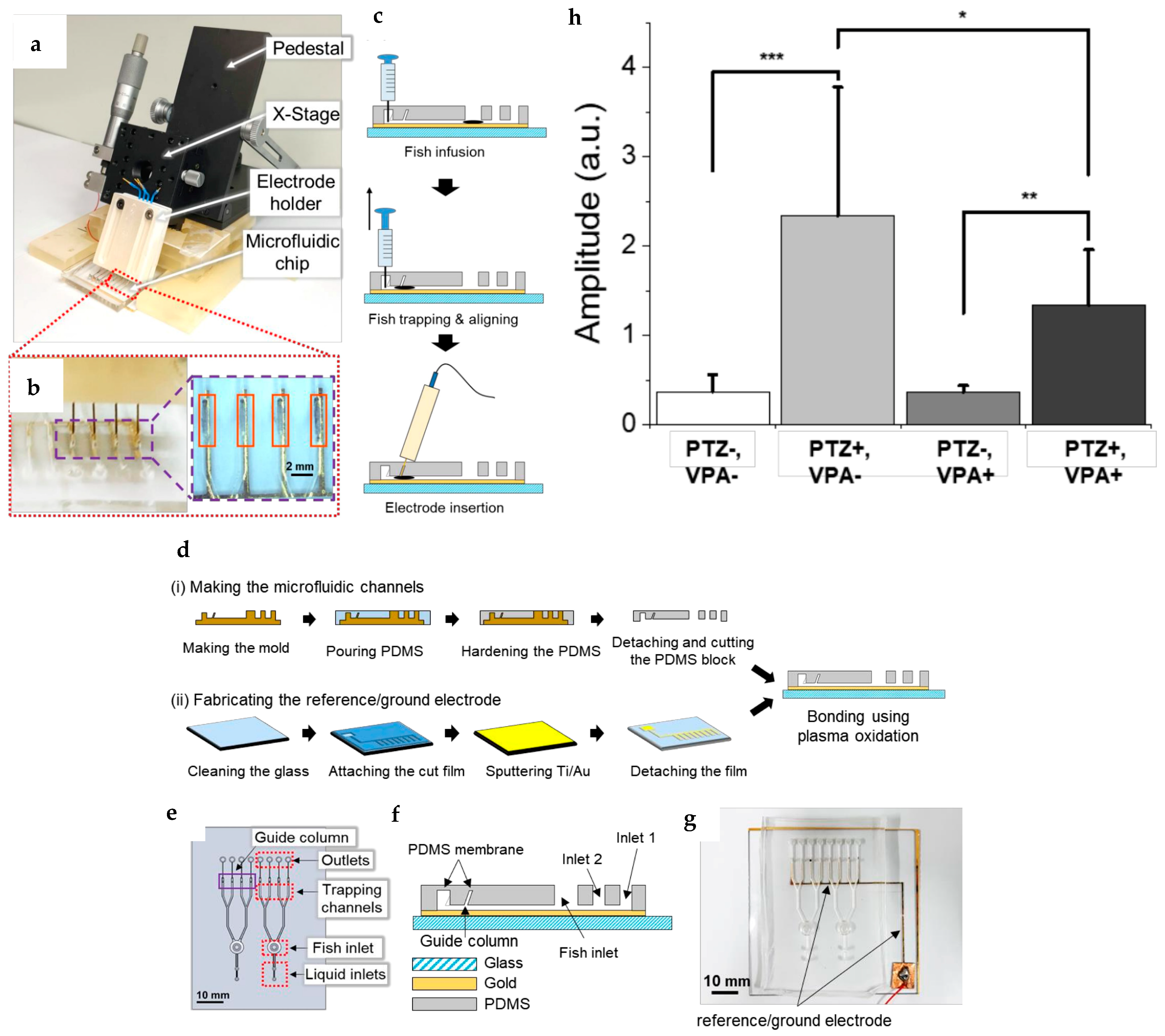
Lee et al. [57] introduced a similar approach for invasive EEG monitoring from multiple zebrafish larvae under the influence of valproic acid (VPA) and pentylenetetrazol (PTZ) using optimized microfluidic channels (Figure 14b,e). Although, this design incorporated a sputtering technique to fabricate gold reference and ground electrodes (Figure 14g) on a glass surface, which was subsequently bonded to a PDMS block using plasma oxidation (Figure 14d,f). Tungsten needle electrodes, similar to those used in previous study as mentioned above, were employed for recording. These electrodes were inserted into the microfluidic channels from outside at a precise angle of 51 degrees to accurately target the heads of the zebrafish (Figure 14a,c). The microfluidic chip provided stable fixation for the zebrafish larvae during EEG recording, eliminating the need for additional stabilizing agents like agarose. Moreover, the setup allowed sequential exposure of the larvae to VPA and TPZ during the EEG recording without causing disturbances that could compromise the signal quality. The system achieved a success rate of 75% for EEG recordings, with potential for improvement through finer adjustments of electrode movement. Figure 14h indicates the relative change in signal amplitude of non-treated (PTZ−, VPA−), non-treated with PTZ application (PTZ+, VPA−), VPA-treated (PTZ−, VPA+), and VPA-treated with PTZ application (PTZ+, VPA+) groups over the entire frequency range. This innovative design presents a significant advancement for real-time neurophysiological studies in zebrafish, enabling reliable and disturbance-free EEG recordings under various experimental conditions.
In conclusion, advancements in microfluidic and high-throughput technologies have revolutionized zebrafish-based research, enabling precise drug screening, toxicity testing, and neurophysiological studies. These innovations enhance experimental accuracy, efficiency, and scalability, reinforcing zebrafish as a pivotal model in biomedical research.

5. Novel Stimulation and Transportation Methods

The responses of zebrafish to external stimuli—such as chemical, electrical, mechanical, hydraulic, sound, and visual cues—have been a focal point of research for years [106,107,108,109]. The integration of advanced imaging techniques with sophisticatedly fabricated microfluidic platforms has significantly enhanced the qualitative and quantitative assessment of these responses. Furthermore, insights gained from studying zebrafish responses to such stimuli have led to notable advancements in the precise transportation of zebrafish larvae, enabling controlled movement in desired directions and orientations and different dimensions in drug and disease studies.
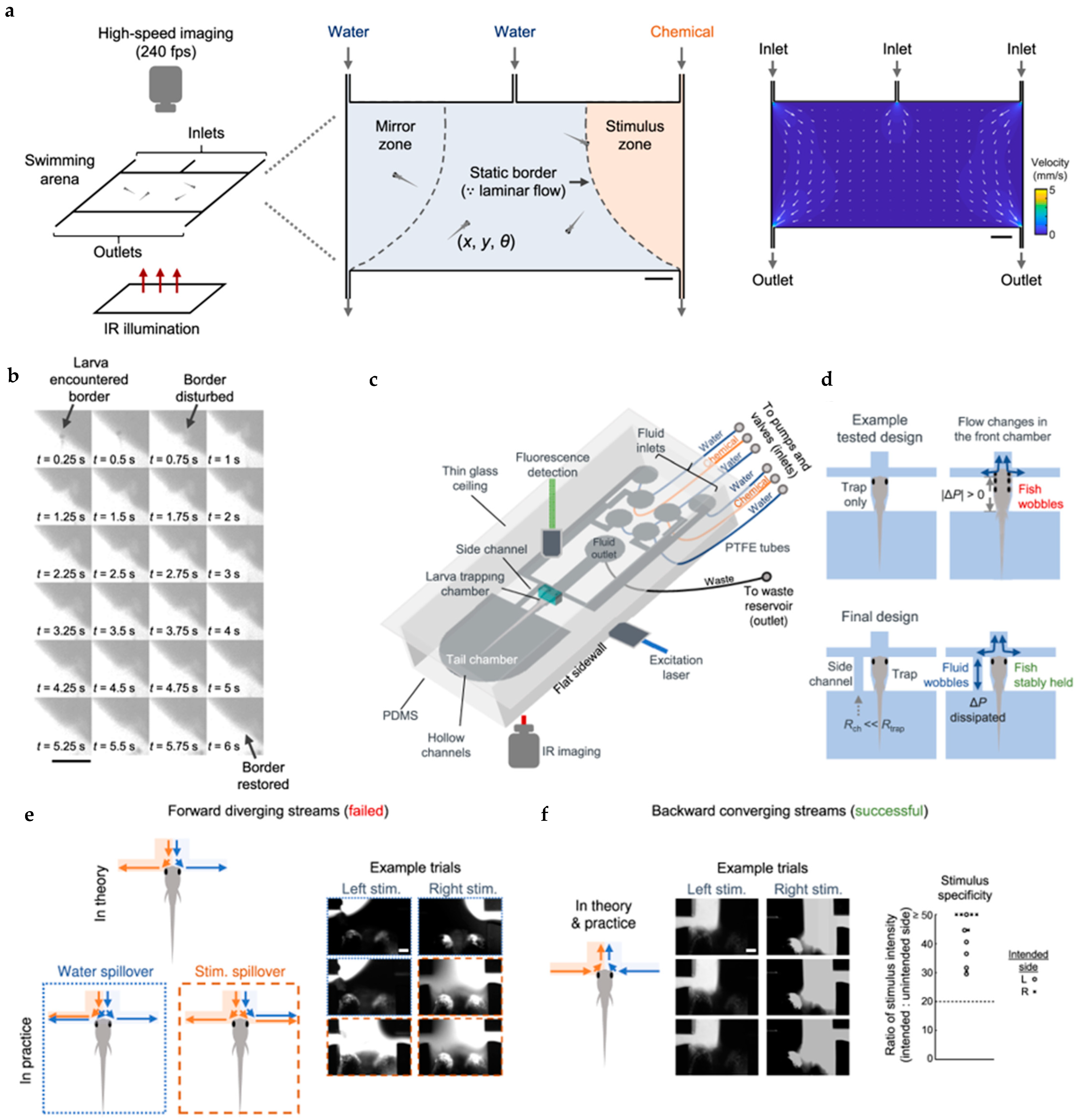
Samuel et al. [46,47] developed two innovative systems—a fluidics-based swimming arena and an integrated microfluidics-light sheet fluorescence microscopy (microfluidics-LSFM) platform—designed to deliver spatiotemporally precise chemical cues using laminar fluid flows. The schematics of the swimming arena and the microfluidics-LSFM system are illustrated in Figure 15a and Figure 15c respectively. In the swimming arena, laminar flow was employed with equal flow rates across three inlets to maintain distinct fluidic stream zones over time, even with the active swimming of zebrafish larvae. When a larva crossed the chemical boundary, the disruption was transient and restored within seconds (Figure 15b). This ensured a clear separation of the fluidic stream zones in the arena in the presence of actively swimming larval objects. The microfluidics-LSFM system utilized laminar flow to regulate chemical stimuli with high precision, allowing selective delivery to one or both olfactory placodes (OPs) of zebrafish larvae. Use of a side channel helped to dissipate the pressure change due to the flow change in front chamber (Figure 15d). A backward converging stream pattern was implemented to prevent spillover of water or stimuli between zones (Figure 15e,f). Coupled with light sheet fluorescence microscopy, this system achieved cellular resolution for whole-brain imaging. Using cadaverine as the chemical stimulus, the study demonstrated clear avoidance of it by zebrafish larvae over longer sampling periods, a finding that contrasts with earlier studies reporting no distinct avoidance of cadaverine [110]. These systems provide powerful tools for studying zebrafish behavior under various chemical influences and offer insights into the neurological responses elicited by such stimuli. They highlight the utility of combining microfluidic precision with advanced imaging to explore the complex interplay between chemical cues and neural outcomes in zebrafish.
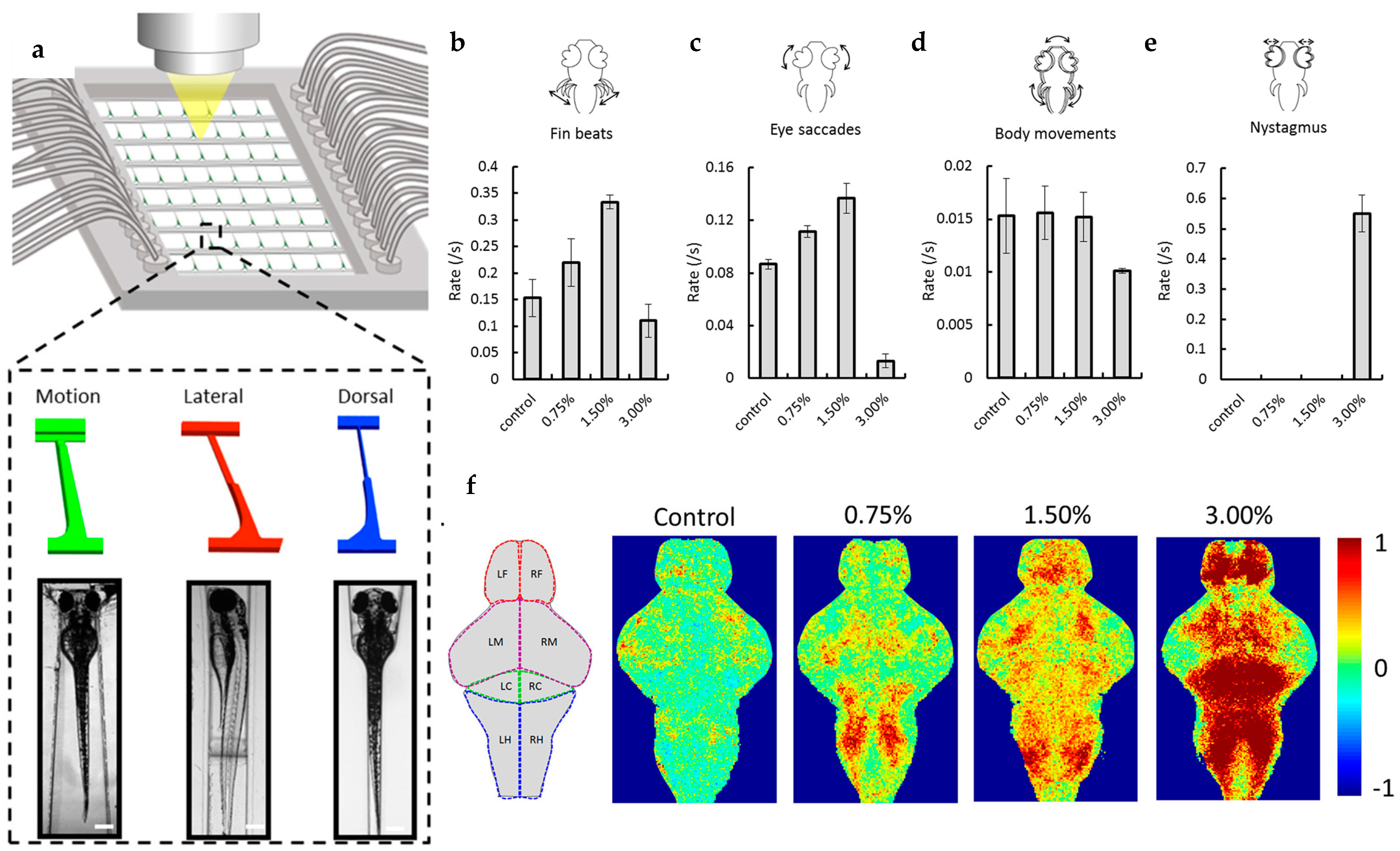
Lin et al. [80] developed an autonomous microfluidic system using a series of chips to study ethanol-induced acute responses in larval zebrafish across multiple organs. This system enabled high-throughput, gel-free, and anesthetic-free manipulation, allowing real-time observation of behavioral and physiological changes at the cellular resolution, overcoming the limitations of traditional immobilization methods [111,112]. The system comprised three types of chips—motion, lateral, and dorsal—each utilizing hydrodynamic force to load and immobilize larvae, with the primary difference being the shape of the trapping channels to facilitate the observation of behavior, cardiac function, or brain activity (Figure 16a). The motion chip was used to analyze pectoral fin beats, eye saccades, and body movements in 7 dpf larvae exposed to ethanol concentrations ranging from 0.00% to 3.00% v/v. At low ethanol levels (0–1.5%), pectoral fin beats increased from 0.15 ± 0.03 to 0.33 ± 0.01 beats/s, but dropped significantly to 0.11 ± 0.03 beats/s at 3.00% (Figure 16b). A similar pattern was observed for eye saccades, which increased at lower concentrations but decreased significantly at 3% (Figure 16c). Although body movements did not increase initially, they were substantially reduced at the highest ethanol concentration (Figure 16d), and a distinct locomotion pattern, eye nystagmus, emerged (Figure 16e). The lateral chip, used with fluorescence microscopy, revealed that heart rate slowed in a dose-dependent manner across ethanol concentrations of 0.00%, 0.75%, 1.50%, and 3.00% v/v. Meanwhile, the dorsal chip combined with calcium imaging showed that ethanol induced dose-dependent stimulation of brain activity, starting in the caudal hindbrain at 0.75% and spreading to the cerebellum, ventral midbrain, and forebrain at higher concentrations (Figure 16f). Exposure to 3.0% ethanol significantly slowed most behavioral activities and heart rate, while the forebrain showed the most intense neuronal excitation at this level.
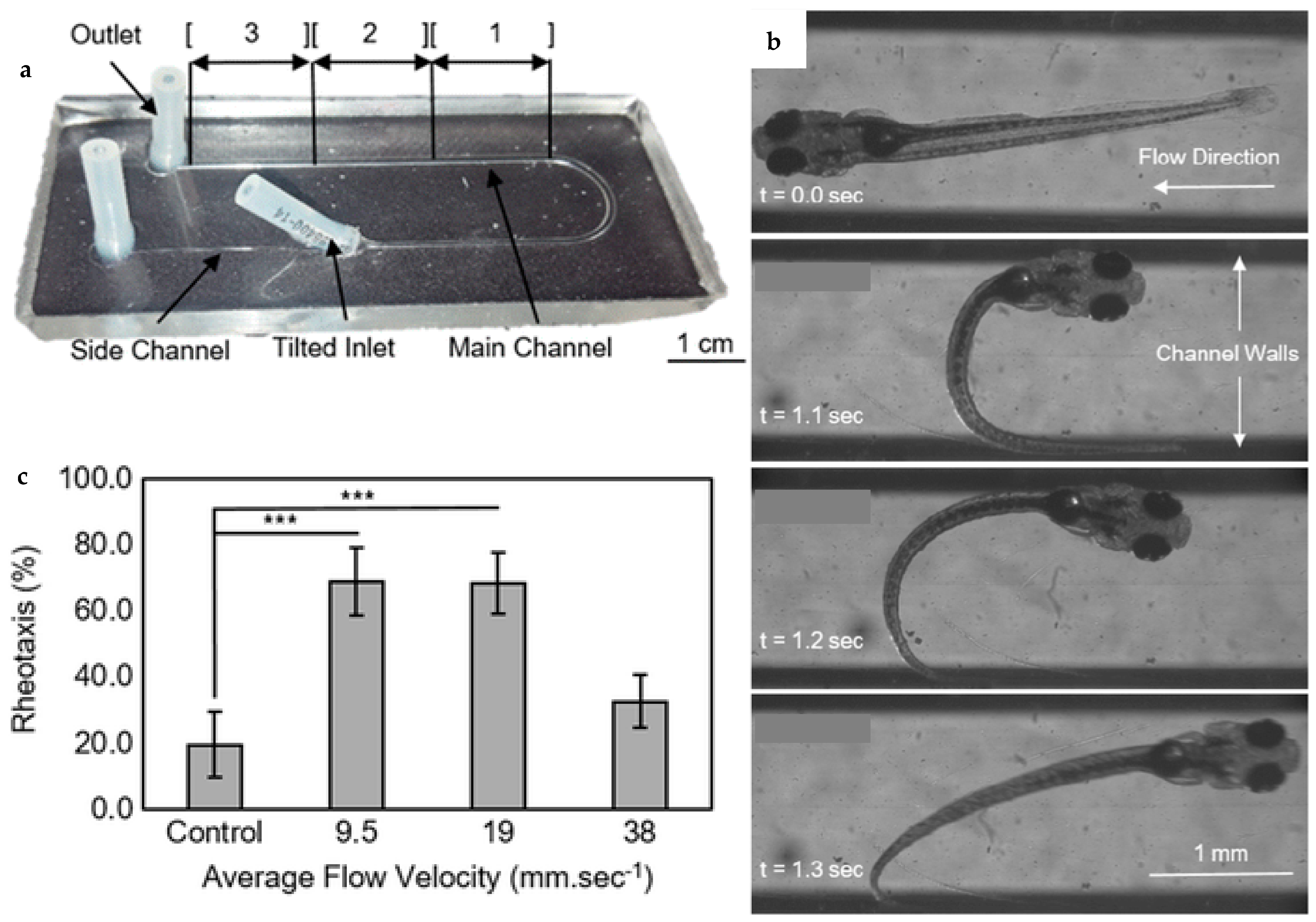
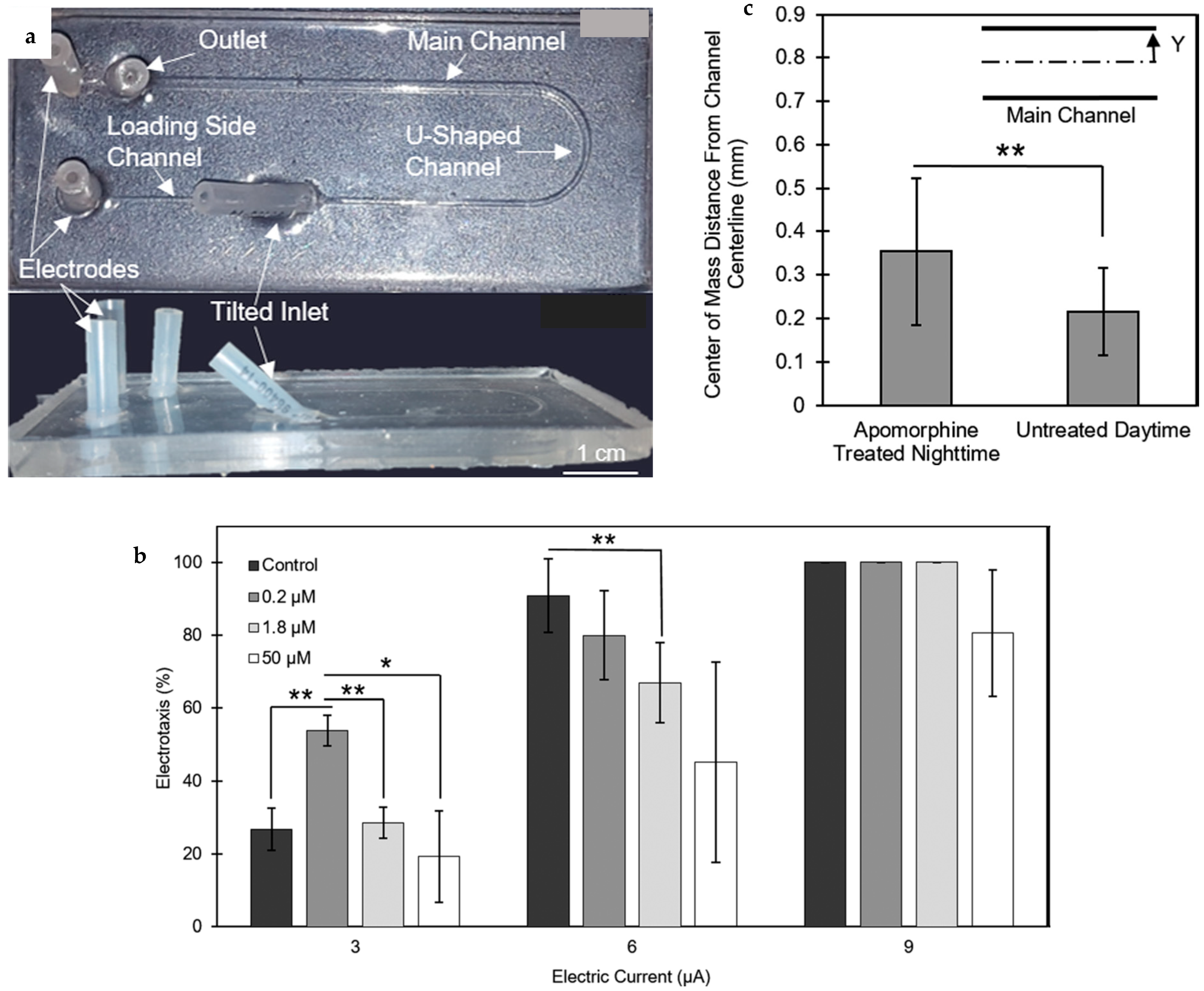
Peimani et al. [48] developed a microfluidic device to quantitatively investigate rheotaxis—the ability of zebrafish larvae to orient and swim against a water current. The rheotactic response was measured in terms of the larvae’s response rate and location along the channel at varying flow velocities. The device was composed of several functional components: a 45° angled inlet tube for smooth and efficient larval loading, a side channel to protect larvae from colliding with the base and walls during loading, a main channel for conducting rheotaxis assays, and a U-shaped narrowing channel (1.6 mm to 0.9 mm) serving as a fluidic valve to retain the larvae within the device (Figure 17a). To evaluate the larvae’s sensitivity to flow, the main channel was divided into three equal sections: Section 1 (initial position), Section 2 (mid-channel), and Section 3 (posterior position). The effect of coaxial flow velocity in the range of 9.5–38 mm·s−1 on the rheotactic response of 5–7 dpf zebrafish larvae was investigated. For instance, once a larva was exposed to a 19 mm·s−1 flow, it exhibited positive rheotaxis within 1.3 s of stimulation as shown in Figure 17b. As evident from Figure 17c, flow velocities below 9.5 mm/s did not induce a significant positive rheotactic response, likely due to the underdeveloped hair cells in the superficial neuromasts of the larvae, as suggested by the earlier studies [94,113]. Conversely, flow velocities exceeding 38 mm/s also failed to evoke robust rheotaxis, as the force of the flow ejected the larvae from the channel before a response could be observed. The study highlights the need to extend the length of the channel for further investigations into rheotactic behavior at higher velocities. Additionally, the throughput of the device could be enhanced by incorporating multiple parallel channels, enabling simultaneous analysis of larger populations. This microfluidic platform offers a precise and efficient tool for studying rheotaxis individually, ruling out any possibility of behavioral alterations in a group and flow sensing mechanisms in zebrafish larvae.
Peimani et al. [49] expanded the capabilities of their previously developed microfluidic device to systematically study zebrafish larvae’s response to electrical fields and their electrotactic behavior. The upgraded device incorporated two wire electrodes inserted into the side channel tubes (Figure 18a) to apply controlled electrical signals. These modifications enabled the investigation of the molecular and physiological basis of electrotaxis, the effects of dopaminergic system agonists and antagonists, and the potential screening of pharmacological tools relevant to neurodegenerative disorders. In initial experiments, electric currents of 3 μA and 15 μA were used to examine the electrotactic response of zebrafish larvae in the tail-to-head direction, with the anode positioned at the tail. The larvae displayed a clear tendency to move toward the anode electrode within the channel. Survival and morphological assays conducted on 5–7 dpf zebrafish larvae revealed that electrical currents below 10 μA were safe for further studies, as higher currents increased the risk of morphological abnormalities. The study also uncovered a time-of-day dependency in the electrotactic behavior of zebrafish larvae, with significantly reduced responses to electrical signals during the night compared to the daytime. Treating the larvae with apomorphine, a nonselective dopamine agonist, altered the nighttime electrotactic response, demonstrating the critical role of dopamine receptors in regulating this behavior (Figure 18b). Larvae exposed to apomorphine at night exhibited enhanced electrotaxis but displayed struggling swimming patterns and trajectories closer to the channel wall (Figure 18c). By contrast, larvae tested during the day without drug exposure showed more streamlined forward swimming near the channel’s centerline. Further assays with selective dopamine agonists SKF-38393 and Quinpirole identified a dominant involvement of D2-dopamine receptors in electrotactic behavior. This research not only highlights the complex interplay between dopaminergic signaling and electrotaxis but also establishes the upgraded microfluidic platform as a powerful tool for studying neural and behavioral responses, with applications in drug discovery and neurophysiological research.
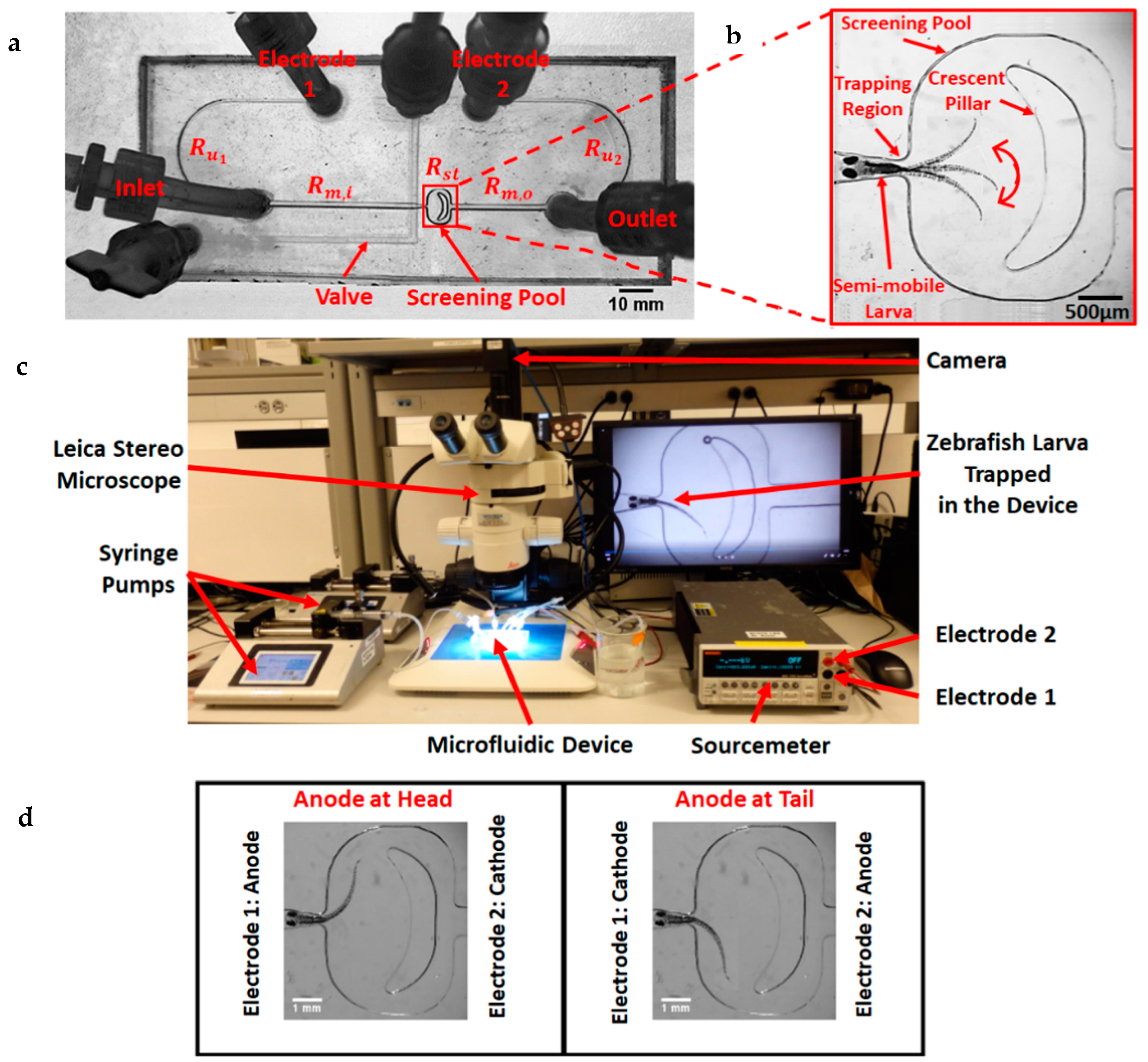
One limitation of the above device developed by Peimani et al. [49] was its inability to phenotypically characterize electrical signal-induced responses due to the rapid movement of zebrafish larvae along the channel. To address this issue, Khalili et al. [50] introduced a modified microfluidic device that partially immobilized the larva’s head while leaving its mid-body and tail unrestrained. This design allowed for the imaging and quantitative phenotyping of motor behaviors in response to electrical stimulation (Figure 19c). The updated device incorporated additional features, including a screening pool and a trapping region (TR) (Figure 19b). The trapping region was specifically designed to secure the larva’s head using a geometry optimized for this purpose, along with a bottom valve formed by a PDMS membrane placed between the top and bottom PDMS layers (Figure 19a). This configuration facilitated precise trapping and reduced undesired movements, enabling detailed phenotypic analysis. Using this setup, electrically evoked responses in zebrafish larvae were quantified in terms of tail beat frequency (TBF) and response duration (RD). As proof-of-concept applications, the device was employed for movement behavior screening in chemical and genetic assays. Experiments involving zebrafish exposed to the neurotoxin 6-hydroxydopamine demonstrated for the first time that the neurotoxin impairs electrically evoked responses, while levodopa treatment effectively rescues the response. Additionally, larvae with a pannexin1a (panx1a) gene knockout revealed that panx1a plays a critical role in electrically evoked movement. This advanced microfluidic platform overcomes prior limitations and serves as a powerful tool for studying electrically evoked behaviors in zebrafish larvae, with broad applications in neurotoxicology, drug screening, and genetic studies.
In their follow-up study, Khalili et al. [51] investigated the effects of electrical signal direction, voltage magnitude, and habituation to repeated electrical pulse exposures on zebrafish larvae responses. The study revealed that changes in the direction of the electrical signal significantly affected tail beat frequency (TBF) (Figure 19d) and response duration (RD), while variations in the voltage drop across the device had minimal impact on these parameters. However, the voltage drop across the trap/fish body showed discrepancies in TBF and RD as indicated in the study. Habituation to electrical signals where larvae ceased responding to repeated stimulation was examined using pulses with varying interstimulus intervals (ISIs). For shorter ISIs of 5 s, larvae stopped responding after a certain number of pulses. When an intermediate recovery period of approximately 5 min was provided, larvae regained their responses to subsequent electrical pulses. A similar recovery effect was observed when a light pulse was applied instead of the recovery period, demonstrating an alternative method to reset responsiveness. To improve throughput, five modified designs of the device were tested by incorporating an indirect flow channel concept in the follow-up study [52]. The optimized one reduced testing time per larva by 60% while improving loading and orientation efficiencies by over 80%. Importantly, the new design preserved the consistency of RD and TBF measurements compared to the earlier device. This enhanced platform demonstrates increased efficiency and reliability, making it a valuable tool for high-throughput behavioral studies in zebrafish.
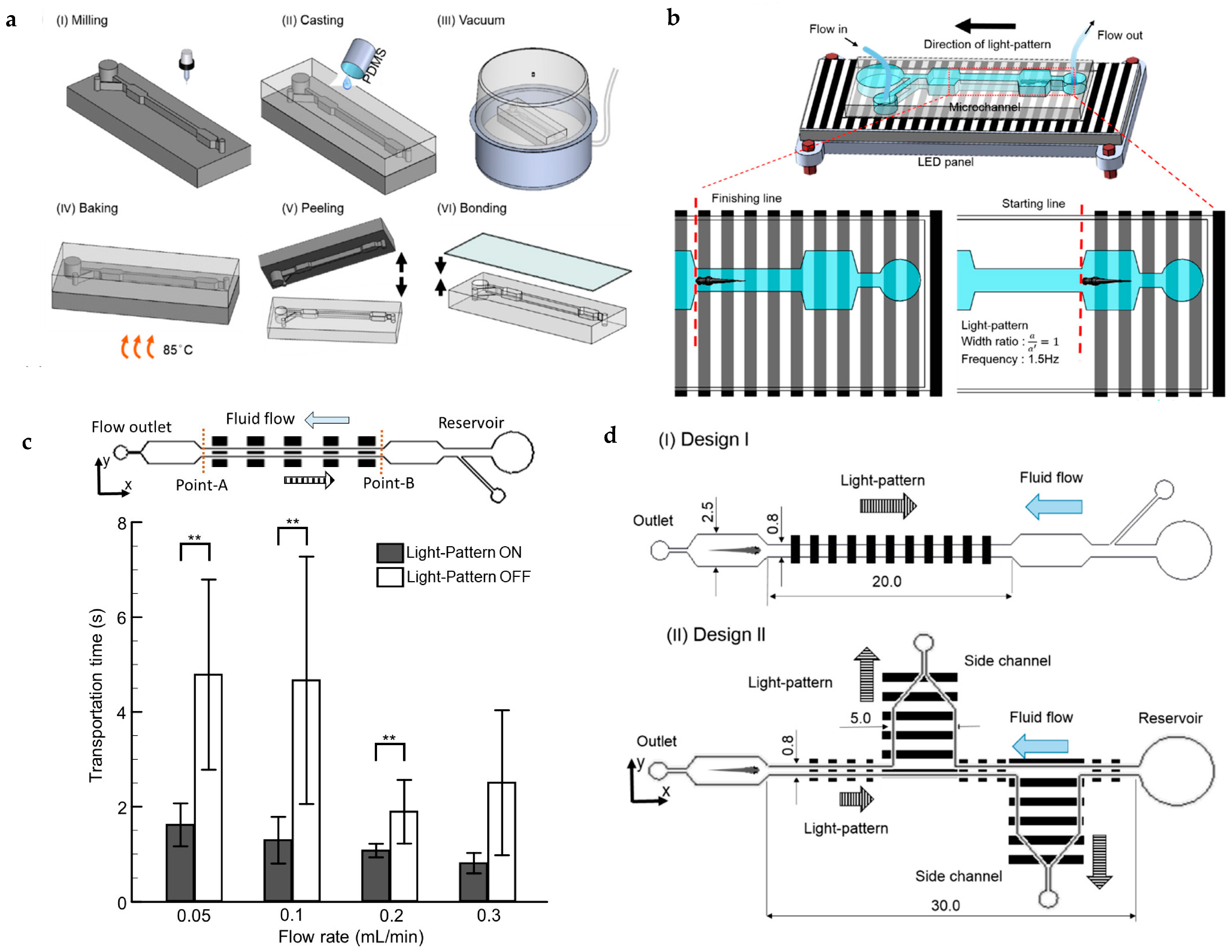
Panigrahi et al. [81] proposed an innovative methodology for efficiently transporting zebrafish larvae within complex microfluidic networks by leveraging their natural responses to visual and hydromechanical cues. Visual stimulation was achieved through computer-animated moving gratings controlled by an in-house-developed interface (Figure 20b), while hydromechanical stimulation was provided by adjusting the flow rate using a syringe pump through the microchannel produced by PDMS casting (Figure 20a). Both modalities played a critical role in facilitating larval transportation and orientation control. The study demonstrated that optimizing the magnitude of these stimuli significantly enhanced transportation efficiency. For example, by tuning the flow rate to 0.1 mL/min and using grating parameters with a temporal frequency of 1 Hz, the average transportation time for 5 days post-fertilization larvae was approximately three times faster than when hydromechanical cues were used alone (Figure 20c). Additionally, the system included two test sections positioned at different locations within the device (design II in Figure 20d) to analyze larval migration in response to external optical stimuli. Results indicated that larval migration was symmetric and predominantly driven by optical stimuli, highlighting the effectiveness of visual cues in guiding larval movement. This methodology offers a robust approach for precise transportation and orientation control of zebrafish larvae in microfluidic systems, opening new possibilities for high-throughput biological studies.
A similar strategy was employed earlier by Mani et al. [82], who optimized the grating frequency and grating width ratio to minimize the transportation time of zebrafish larvae through three distinct pathways within the device. Their device design included a microwell, a chamber, and three imaging sections. To facilitate precise visual stimulation, a custom-made graphical user interface (GUI) was developed to project moving gratings onto the bottom surface of the microfluidic device. This approach highlights the critical role of visual cues in enhancing larval transportation efficiency and orientation control within microfluidic systems.
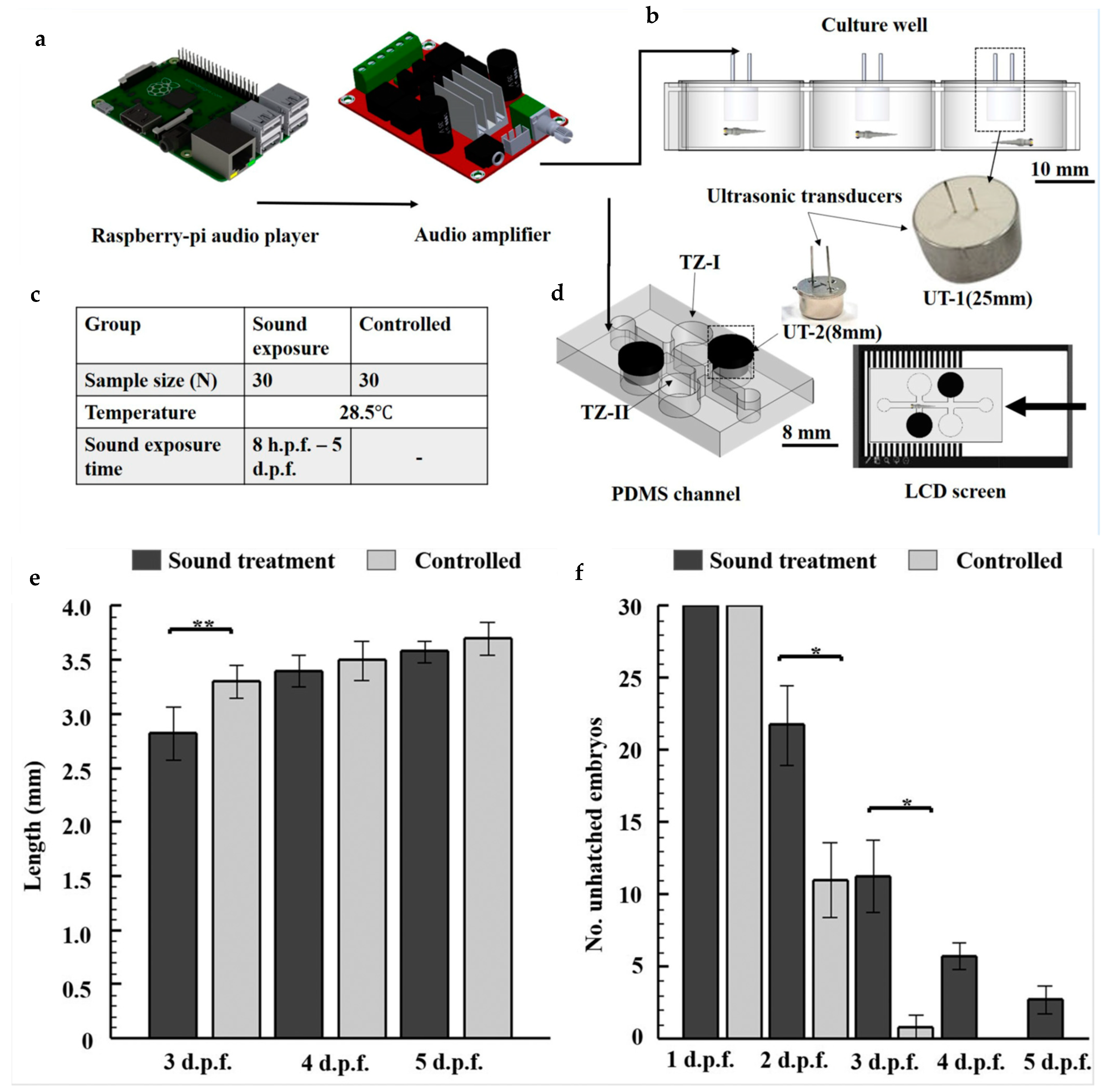
Researchers are increasingly interested in understanding the effects of sound stimuli on the behavior of zebrafish, as the impact of noise exposure on laboratory-grown zebrafish remains poorly understood. Mani et al. [83] investigated this by exposing zebrafish embryos to loud background noise (≥200 Hz, 80 ± 10 dB) for five days within a microfluidic environment. A 25 mm ultrasonic transducer, connected to a Raspberry Pi audio player and amplifier (Figure 21a), was used to deliver traffic noise to the embryos cultured in six-well plates (N = 4 dishes, 30 embryos per dish, Figure 21b). The culturing matrix of the control and sound treated larvae is shown in Figure 21c. The study found a significant difference in the length of sound-exposed larvae compared to the control group at 3 days post-fertilization (dpf), although no such difference was observed at 4 and 5 dpf (Figure 21e). This could be due to a delay in hatching caused by disruption of the embryos’ circadian rhythm by sound exposure. Additionally, the sound-treated group showed a lower hatching rate (Figure 21f) and exhibited stress-induced effects such as depleted yolk energy reserves and malformations in the trunk or tail regions. Further analysis of the optomotor response (OMR) and acoustic responses using trapping zones and transducers (Figure 21d) revealed that control larvae responded more to sound cues than visual ones, whereas sound-treated larvae continued to follow visual cues. This suggests that the noise exposure may have damaged the mechanosensory hair cells responsible for detecting sound. Overall, the study highlights that locomotor behavior in zebrafish larvae is more influenced by acoustic stimuli than optical stimuli in microfluidic environments.
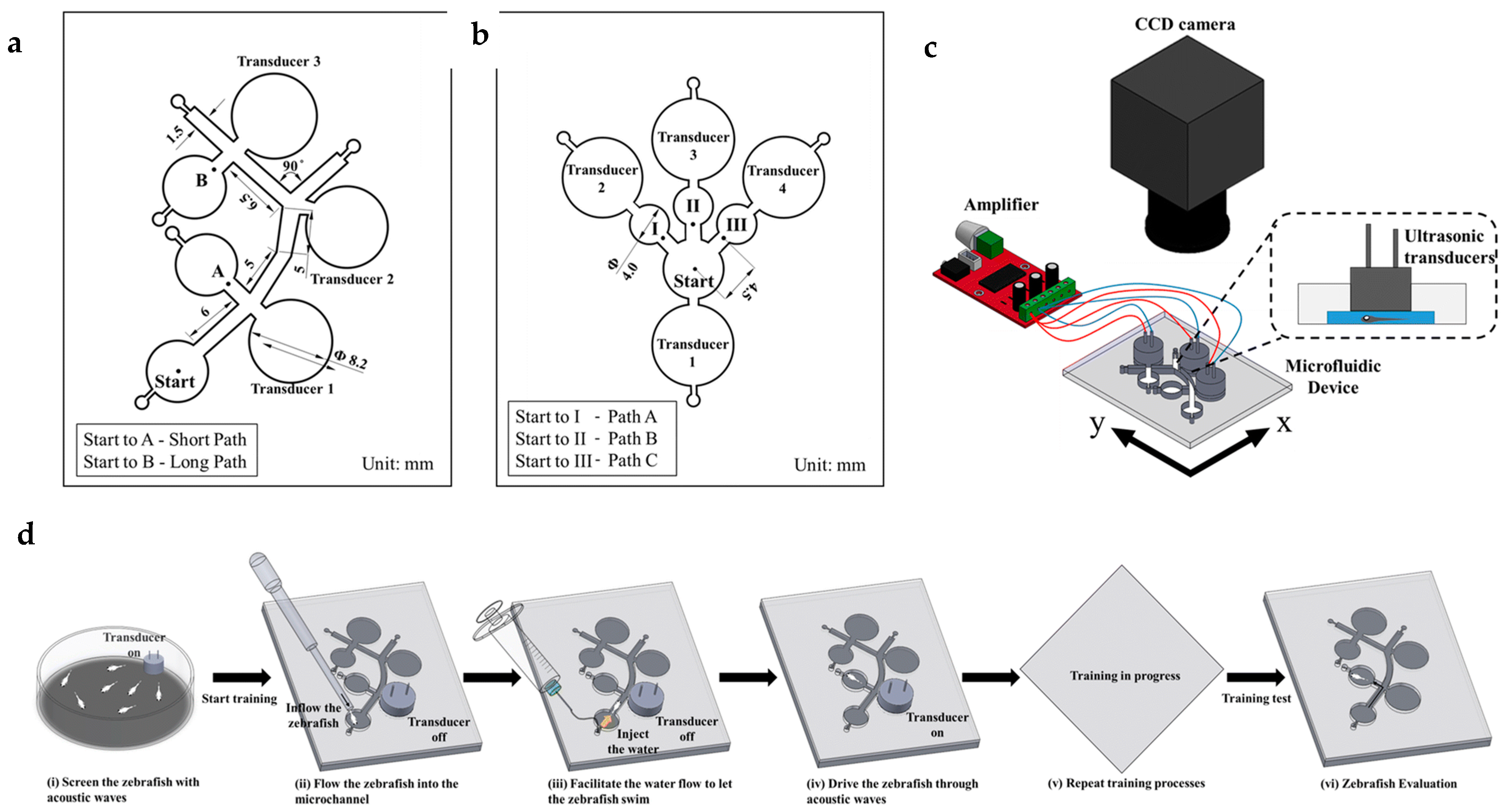
Using sound stimuli, Loganathan et al. [84] proposed a novel microfluidic device to investigate spatial memory in zebrafish, which is the ability to recall the location of objects and places as well as the relationships between them. The device was fabricated using a combination of computerized numerical control micromachining techniques and PDMS casting processes. It allowed for the analysis of various motion parameters, including curvilinear speed (VCL, mm/s), straight-line speed (VSL, mm/s), and motion linearity (LIN = VSL/VCL), under the influence of acoustic stimuli produced by an ultrasonic transducer linked to a high-resolution digital class D audio amplifier. Figure 22a illustrates the geometric design of the device, incorporating short and long paths to facilitate spatial learning in zebrafish larvae. Sound stimuli generated by the transducers were used to guide the larvae through these paths to help them acquire spatial information. Figure 22b details the geometric design of the microfluidic chip used to test the consistency of the startle response (C-bend) triggered by the experimental setup, while Figure 22c presents a schematic of the entire system. Figure 22d outlines the different stages of the sequential learning and testing processes for the zebrafish larvae. To evaluate the level of learning in the larvae, a metric called latency was used to measure the response time between stimuli. Additionally, a memory extinction parameter known as freezing was utilized to assess the loss of conditioned aversion in the larvae, quantifying the extent of retained memory over time. The study examined the responses of 4–6 days post-fertilization (dpf) larvae to sound frequencies of 200, 600, and 1200 Hz with different waveforms. The highest curvilinear velocity (VCL) and straight-line velocity (VSL) were recorded at 1200 Hz with sawtooth waves, measuring 19.98 ± 14.51 mm/s and 8.94 ± 5.14 mm/s, respectively. Memory retention was evaluated using latency and freezing parameters, with 6 dpf larvae showing 42.5 ± 4.8% freezing in the short path and 19.3 ± 3.7% in the long path at the end of a 30-min test. The findings suggest that zebrafish larvae can develop and maintain spatial memory, with higher sound frequencies enhancing both startle responses and memory retention.
All these innovations have enabled efficient movement guidance, high-throughput screening, and deeper insights into neurological and physiological responses. These advancements have opened up new avenues in the fields of drug and disease research as well.

6. Microinjection Techniques and Sperm Retention Studies

To study the disease mechanisms, it is essential to inject drugs or cells into specific organs or body parts of the zebrafish. Manipulating spherical targets like embryos and cells are relatively easier and is facilitated using well-established techniques [114,115,116]. However, methodologies for zebrafish larvae with complex organ systems are still underdeveloped. Moreover, often it is required to rotate the larvae in certain orientation for proper view of target organs from certain angles. Conventional methods involved for these experiments suffer from lower efficiency, imprecision, and lower throughput. Hence, the development of methodologies to meet these challenges has been a focus over the years.
On another note, considering the extent of the use of the zebrafish as suitable animal model, more than 20,000 different types of zebrafish lines have existed to date [117]. Accommodating all the developed zebrafish lines in the current laboratory setup is a challenge. To meet this challenge, collection and cryopreservation of zebrafish sperm represent an emerging choice. Based on requirements, these sperm are collected, activated, and introduced into eggs for fertilization. However, manual methods and cryopreservation protocols causing molecular alterations at the cellular level result in lower success rates in fertilization. In recent years, various microfluidic technologies have been developed to manipulate, sort, image, and select high quality sperm by adjusting their behaviors. This section will discuss some novel techniques developed in recent years to assist microinjection and selection of high-quality zebrafish sperm.
Zhang et al. [62] introduced a customized microfluidic chip designed to control the orientation and aspiration of zebrafish larvae for microinjection purposes. This microfluidic device ensures that larvae are oriented tail first upon reaching the channel exit. Fabricated from polydimethylsiloxane (PDMS), the device operates using three microinjection pumps. The first pump is responsible for delivering one larva at a time to the channel entrance, which is strategically positioned at the center of the field of view (FOV). The initial FOV image is captured and stored as a template. Pump 1 then continues infusion until the FOV image changes significantly from the template, indicating the entry of a larva into the channel. Based on the orientation of the larva (head first or tail first), the other two pumps are activated to ensure the larva exits the channel tail first. To immobilize the larva, a nonlinear aspiration model is employed, aspirating its tail. To protect the fragile body of the larva, the syringe connected to the holding pipette is pre-filled with a precise amount of air before aspiration. This precaution minimizes the risk of physical damage while maintaining the larva’s stability during microinjection procedures.
Zhuang et al. [63] developed a semi-automated, simple-structured vision servo system for zebrafish larva heart microinjection. The system consists of three main components: a vision module, a control module, and an injection module. A k-means clustering algorithm is employed to simultaneously locate all larvae within the field of view (FOV). Binary images representing the four typical postures of larvae, including sideward, upward, rightward, and leftward, are used as templates. The presence of a larva is detected by matching these templates, which can be rotated to different orientations as needed. A rolling model is also constructed, utilizing slice images of the larva’s body to estimate the height of the larva’s heart. To ensure precise positioning and orientation for successful microinjection, a two-dimensional rotation control mechanism is proposed. This mechanism employs a motorized translational stage and a glass capillary to align and secure the larva. The developed visual detection method demonstrates a 100% success rate when the larva’s heart is oriented leftward or rightward and a 90% success rate for other postures. Additionally, the rotation control approach achieves a high success rate of 97% with a rotation resolution of 0.5°. As a high-efficiency and cost-effective microinjection system, this technology shows promise for applications beyond heart injections, potentially enabling targeted injections into other organs of zebrafish larvae.
For retaining zebrafish sperm, Panigrahi and Chen [85] introduced a novel microfluidic concept by incorporating PDMS baffles into the sidewalls of the device (fabricated by PDMS casting, Figure 23c) to create microscale confinements, resulting in flow stagnation zones. Two distinct designs of the device were proposed (Figure 23a), differing solely in the shape of the PDMS baffles (Figure 23b). The space between the baffles served as the flow stagnation zone, where motile sperm displayed a natural tendency to swim toward the walls of these zones (Figure 23d). However, due to their locomotion dynamics, a small number of spermatozoa were observed swimming back into the primary flow. Among the two designs, the device with the modified baffle configuration (design II in Figure 23b) demonstrated superior retention of motile sperm compared to the standard baffle design, which was quantified using the parameter sperm retrieval efficiency which is the ratio of the difference between the number of sperm swimming in and the number of sperm swimming out to the number of sperm swimming in. Figure 23e indicates better retrieval efficiency of design II compared to that of design I at a flow rate of 0.2 μL/min. Figure 23f shows the retrieval efficiency of design II at different flow rates, and it can be seen that maximum efficiency is observed at a flow rate of 0.7 μL/min. This advancement represents a significant step forward in optimizing zebrafish in vitro fertilization techniques in laboratory settings.
Huang et al. [86] developed an artificial cilia-based micromixer to enhance the activation of zebrafish sperm, addressing the low efficiency typically associated with manual mixing methods. The device, fabricated from PDMS, features an array of artificial cilia composed of neodymium–iron–boron particles mixed with a PDMS solution at a 1:4 ratio (Figure 24a,b). These cilia were magnetized using an external magnet, and their movement was actuated using a magnetic stimulation system that induced circular motion (Figure 24c). Through optimization, the ideal frequency and duration for cilia activation were determined to be 1 Hz and 5 s, respectively. The proposed device demonstrated a sperm activation efficiency exceeding 60%, significantly outperforming the average 44% activation achieved with manual mixing. This innovative approach offers a promising alternative for improving sperm activation in zebrafish in vitro fertilization processes.
In summary, although there have been some advancements in the sector of microinjection and sperm studies in recent years as discussed above, these fields still need more rigorous focus and attentions from the researchers for further advancements in the upcoming days given the critical nature and these necessities.

7. Development of a Smart Microfluidics-Based Fish Farm for Zebrafish Screening

MEMS (Micro-Electro-Mechanical Systems) technology has emerged as a transformative tool for automation in fields such as Lab-on-Chip and Fish-on-Chip [25,26,27,28,29,30,31,32,33,34,35,36,37,38,39,40,41,42,43,44,45]. With advancements in the fabrication of miniaturized sensors and actuators, real-time feedback from microsystems can now be utilized for the automated actuation of various components within these devices. As MEMS and microfluidics technologies continue to advance, there is a growing demand for fully automated microfluidic systems that enable smart, high-speed zebrafish testing without the need for traditional fish facility support. This section discusses the concept of such an automated microfluidic-based fish farm.
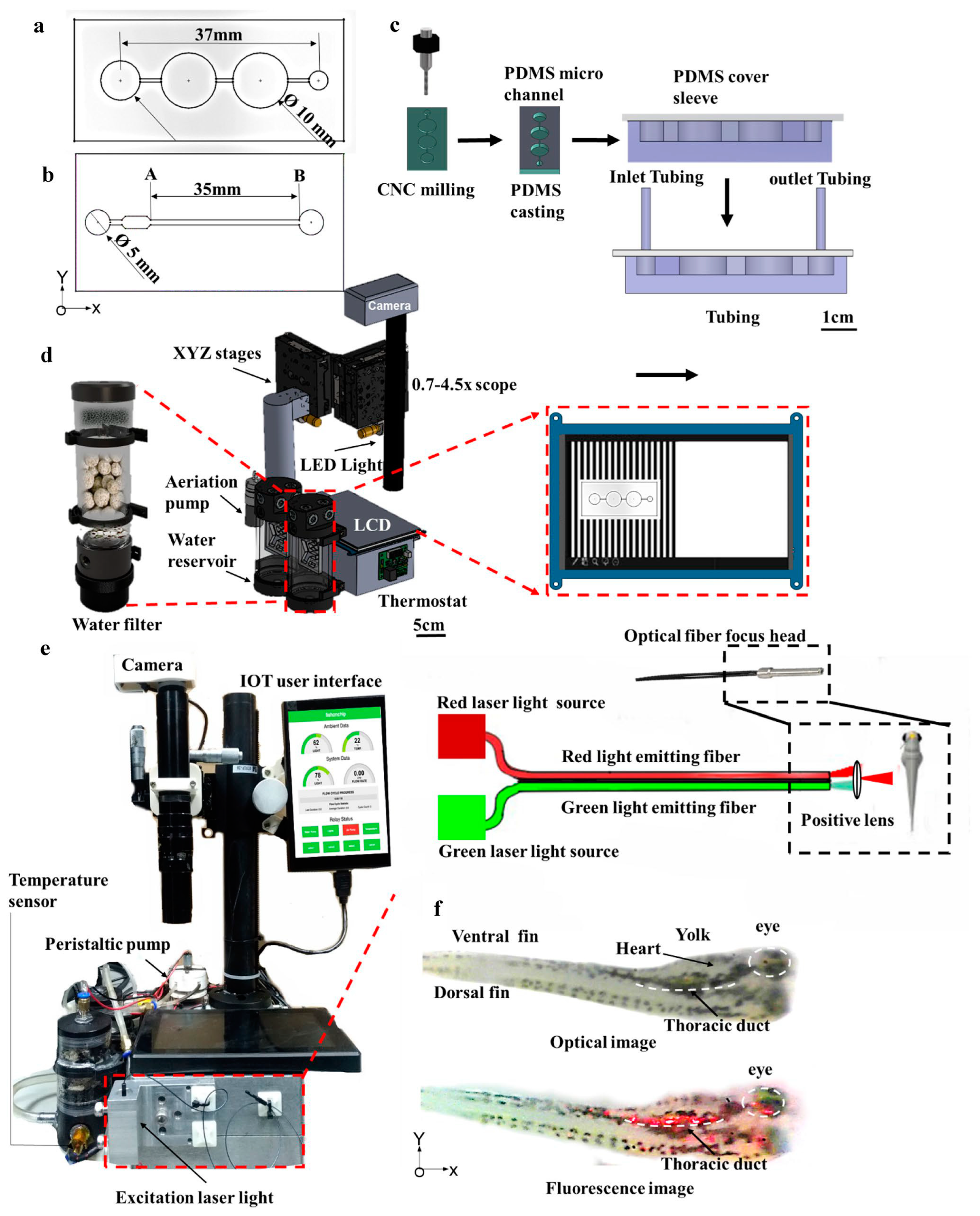
Mani et al. [118] introduced a smart microfluidic device (30 larvae at a time) designed for precise temperature control, intangible zebrafish transportation through light patterning, dynamic culturing, and on-chip high-quality imaging. Figure 25a–f illustrate the various components of the smart microfluidic system.
Two device designs were developed for zebrafish transportation within the fish farm:
  • Design 1: This included incubation, observation, and culturing chambers, enabling a dynamic microscale flow-through perfusion and culturing system (Figure 25a).
  • Design 2: This featured a straight long channel with an inlet opening for larvae loading. Effective transportation of larvae was achieved by combining tuned water flow with in-house developed animation patterns (Figure 25b).
The automated fish farm was optimized and integrated into a comprehensive system featuring a three-axis microscope for imaging. A cost-effective LED combined with a modified camera provided imaging capabilities. The original camera optics were replaced with a C-Mount monocular video microscope tube (0.7–4.5× digital lens). Optical fibers with 2 mm beam focusing minimized overexposure of co-cultured larvae, reducing additional stress. A laser light source with green (500–550 nm) and red (600–650 nm) wavelengths was employed for illumination (Figure 25d).
The life-support system included critical components such as a water purifier, temperature and light management, liquid handling systems, an automatic incubator, and a microscope. These components were individually controlled using an IoT (Internet of Things) server to support zebrafish larvae growth (Figure 25e).
A Raspberry Pi computer hosted the IoT server on a local area network. A graphical user interface (GUI) displayed real-time sensor data and allowed users to modify fish farm settings. Sensor data were updated at a rate of 10 Hz using WebSockets (Figure 26a). Key parameters for zebrafish larvae survival—ambient room light, water temperature, channel light exposure, water flow rate, and accessory statuses (e.g., pump, heater, and light)—were monitored and could be regulated using the GUI (Figure 26b).
The survival rate and growth of zebrafish larvae were monitored up to 5 days post-fertilization (dpf) under three conditions:
  • Room temperature (24–26 °C).
  • Controlled temperature (28.5 °C) in a Petri dish.
  • Controlled temperature (28.5 °C) in the fish farm.
This automated system eliminates the need for traditional static culturing methods and manual handling by incorporating automated temperature control, remote zebrafish transport using light patterning, and continuous perfusion for a dynamic culture environment as discussed. The microfluidic chip design facilitates high-throughput zebrafish screening while ensuring precise environmental control, minimizing stress on larvae, and enhancing survival rates. Comparative studies demonstrated that larvae raised in this microfluidic platform exhibited a higher survival rate (100% in the fish farm vs. 96.6% in temperature-controlled Petri dishes and 60% in standard Petri dishes) and better growth rates (3.66 mm at 5 dpf vs. 3.28 mm in Petri dishes). The system also supports real-time behavioral analysis, including locomotor responses to optomotor stimuli and drug effects, using controlled light stimulation. Drug screening experiments showed that caffeine exposure reduced locomotor activity, whereas tricaine significantly suppressed movement. The study also demonstrated an innovative method for self-orientation of zebrafish using the optokinetic reflex (OKR), improving imaging accuracy and reducing manual intervention. The integration of IoT-based real-time monitoring and precise environmental regulation makes this system a robust platform for large-scale zebrafish-based drug screening and behavioral studies, setting a new benchmark for automated fish farm technologies.

8. Conclusions and Future Perspectives

Advancements in microfluidics, combined with MEMS technology, have significantly accelerated the development and adoption of Fish-on-Chip (FOC) technology. This progress has transformed various aspects of zebrafish research, including embryo entrapment, culturing, larvae transportation, phenotypic analysis of responses to external stimuli, real-time imaging, drug and disease studies, microinjection, sperm retention, and activation. These advancements have resulted in greater automation, improved efficiency, and a significant reduction in labor-intensive processes.
The integration of advanced microfabrication techniques, such as laser ablation and 3D printing, alongside traditional soft lithography, has facilitated the development of more complex geometries and improved imaging capabilities. These advancements have contributed to significant milestones, including the creation of comprehensive “all-in-one” platforms for on-chip embryo and larva trapping, culturing, exposure, and analysis. Innovations such as detachable loading tools, optimized culturing chamber geometries, multi-layer device designs, and automated regulation of aquatic conditions—such as temperature, pH, and oxygen levels—have enhanced experimental precision. Additionally, methods for individually removing embryos have helped mitigate the toxic effects of decomposing specimens.
Non-invasive immobilization techniques have also undergone significant improvements, reducing physical stress and minimizing morphological abnormalities in zebrafish larvae. The use of specialized channel geometries to facilitate trapping in various orientations (lateral, dorsal, or partial immobilization) and the incorporation of shape memory alloy (SMA) wires to hold larvae in specific positions represent some of the most notable advancements in this field.
Significant advancements in zebrafish imaging have emerged, including acoustofluidic rotational tweezing, the integration of glass chips with light sheet microscopy for whole-brain imaging under chemical stimuli, and the use of rotational capillaries and artificial cilia for precise orientation control and optical prisms for simultaneous lateral and dorsal imaging. These innovations have introduced new dimensions to the field, enhancing imaging accuracy and experimental capabilities.
Automated zebrafish transportation is essential for high-throughput screening, reducing the need for manual handling. This advancement has been driven by innovative stimulation techniques such as visual moving gratings, electrical signals, sound, and hydraulic flow. By leveraging the zebrafish’s natural responses to these stimuli, significant progress has been made in guiding their movement automatically in desired directions.
Microinjection has advanced with the development of automated orientation control, precise injection positioning through the integration of sophisticated imaging techniques coupled with robust visual detection algorithms.
Despite these significant advancements, there is still room for improvement. Many innovations, such as microinjection, acoustofluidic rotational control, shape memory alloy-based immobilization, light sheet microscopy, laser ablation, and 3D printing, face challenges related to low throughput, high costs, and operational complexity. Addressing these limitations requires further research and refinement. Additionally, technologies like magnet-controlled orientation are expected to gain increased attention due to their versatility and potential advantages. Looking ahead, advancements in microfluidics and MEMS technology are anticipated to offer more efficient and user-friendly solutions to these challenges.

Author Contributions

T.N. and H.T. contributed to the conceptualization and development of this review. All authors have read and agreed to the published version of the manuscript.

Funding

This research received no external funding.

Data Availability Statement

Relevant data are available in the cited literatures throughout the review. It is advised to go through the reference section for detailed info about the cited literature.

Conflicts of Interest

The authors declare no conflicts of interest.

References

  1. Basu, S.; Sachidanandan, C. Zebrafish: A multifaceted tool for chemical biologists. Chem. Rev. 2013, 113, 7952–7980. [Google Scholar] [CrossRef] [PubMed]
  2. White, R.; Rose, K.; Zon, L. Zebrafish cancer: The state of the art and the path forward. Nat. Rev. Cancer 2013, 13, 624–636. [Google Scholar] [CrossRef]
  3. Kalueff, A.V.; Stewart, A.M.; Gerlai, R. Zebrafish as an emerging model for studying complex brain disorders. Trends Pharmacol. Sci. 2014, 35, 63–75. [Google Scholar] [CrossRef]
  4. McGrath, P.; Li, C.-Q. Zebrafish: A predictive model for assessing drug-induced toxicity. Drug Discov. Today 2008, 13, 394–401. [Google Scholar] [CrossRef] [PubMed]
  5. Cassar, S.; Adatto, I.; Freeman, J.L.; Gamse, J.T.; Iturria, I.; Lawrence, C.; Muriana, A.; Peterson, R.T.; Van Cruchten, S.; Zon, L.I. Use of zebrafish in drug discovery toxicology. Chem. Res. Toxicol. 2020, 33, 95–118. [Google Scholar] [CrossRef]
  6. Hwang, H.; Lu, H. Microfluidic tools for developmental studies of small model organisms –nematodes, fruit flies, and zebrafish. Biotechnol. J. 2012, 8, 192–205. [Google Scholar] [CrossRef] [PubMed]
  7. Bayliss, P.E.; Bellavance, K.L.; Whitehead, G.G.; Abrams, J.M.; Aegerter, S.; Robbins, H.S.; Cowan, D.B.; Keating, M.T.; O’Reilly, T.; Wood, J.M.; et al. Chemical modulation of receptor signaling inhibits regenerative angiogenesis in adult zebrafish. Nat. Chem. Biol. 2006, 2, 265–273. [Google Scholar] [CrossRef]
  8. D’Amora, M.; Giordani, S. The Utility of Zebrafish as a Model for Screening Developmental Neurotoxicity. Front. Neurosci. 2018, 12, 976. [Google Scholar] [CrossRef]
  9. Dooley, K. Zebrafish: A model system for the study of human disease. Curr. Opin. Genet. Dev. 2000, 10, 252–256. [Google Scholar] [CrossRef]
  10. Shi, W.; Wen, H.; Lu, Y.; Shi, Y.; Lin, B.; Qin, J. Droplet microfluidics for characterizing the neurotoxin-induced responses in individual Caenorhabditis elegans. Lab Chip 2010, 10, 2855–2863. [Google Scholar] [CrossRef]
  11. Yang, J.; Chen, Z.; Ching, P.; Shi, Q.; Li, X. An integrated microfluidic platform for evaluating in vivo antimicrobial activity of natural compounds using a whole-animal infection model. Lab Chip 2013, 13, 3373–3382. [Google Scholar] [CrossRef]
  12. Zhang, B.; Li, Y.; He, Q.; Qin, J.; Yu, Y.; Li, X.; Zhang, L.; Yao, M.; Liu, J.; Chen, Z. Microfluidic platform integrated with worm-counting setup for assessing manganese toxicity. Biomicrofluidics 2014, 8, 054110. [Google Scholar] [CrossRef]
  13. Chung, K.; Kim, Y.; Kanodia, J.S.; Gong, E.; Shvartsman, S.Y.; Lu, H. A microfluidic array for large-scale ordering and orientation of embryos. Nat. Methods 2010, 8, 171–176. [Google Scholar] [CrossRef] [PubMed]
  14. Hulme, S.E.; Whitesides, G.M. Chemistry and the Worm: Caenorhabditis elegans as a Platform for Integrating Chemical and Biological Research. Angew. Chem. Int. Ed. Engl. 2011, 50, 4774–4807. [Google Scholar] [CrossRef]
  15. Wang, X.; Hu, R.; Ge, A.; Hu, L.; Wang, S.; Feng, X.; Du, W.; Liu, B.-F. Highly efficient microfluidic sorting device for synchronizing developmental stages of C. elegans based on deflecting electrotaxis. Lab Chip 2015, 15, 2513–2521. [Google Scholar] [PubMed]
  16. Bakhtina, N.A.; Korvink, J.G. Microfluidic laboratories for C. elegans enhance fundamental studies in biology. RSC Adv. 2013, 4, 4691–4709. [Google Scholar] [CrossRef]
  17. Yanik, M.F.; Rohde, C.B.; Pardo-Martin, C. Technologies for Micromanipulating, Imaging, and Phenotyping Small Invertebrates and Vertebrates. Annu. Rev. Biomed. Eng. 2011, 13, 185–217. [Google Scholar] [CrossRef]
  18. Kimmel, C.B.; Ballard, W.W.; Kimmel, S.R.; Ullmann, B.; Schilling, T.F. Stages of embryonic development of the zebrafish. Dev. Dyn. 1995, 203, 253–310. [Google Scholar] [CrossRef]
  19. Lieschke, G.J.; Currie, P.D. Animal models of human disease: Zebrafish swim into view. Nat. Rev. Genet. 2007, 8, 353–367. [Google Scholar] [CrossRef]
  20. Hsu, C.-H.; Wen, Z.-H.; Lin, C.-S.; Chakraborty, C. The Zebrafish Model: Use in Studying Cellular Mechanisms for a Spectrum of Clinical Disease Entities. Curr. Neurovasc. Res. 2007, 4, 111–120. [Google Scholar] [CrossRef]
  21. Chan, P.K.; Lin, C.C.; Cheng, S.H. Noninvasive technique for measurement of heartbeat regularity in zebrafish (Danio rerio) embryos. BMC Biotechnol. 2009, 9, 11. [Google Scholar] [CrossRef] [PubMed]
  22. Xu, C.; Volkery, S.; Siekmann, A.F. Intubation-based anesthesia for long-term time-lapse imaging of adult zebrafish. Nat. Protoc. 2015, 10, 2064–2073. [Google Scholar] [CrossRef]
  23. Collymore, C.; Tolwani, A.; Lieggi, C.; Rasmussen, S. Efficacy and safety of 5 anesthetics in adult zebrafish (Danio rerio). J. Am. Assoc. Lab Anim. Sci. 2014, 53, 198–203. [Google Scholar]
  24. Nordgreen, J.; Tahamtani, F.M.; Janczak, A.M.; Horsberg, T.E. Behavioural effects of the commonly used fish anaesthetic tricaine methanesulfonate (MS-222) on zebrafish (Danio rerio) and its relevance for the acetic acid pain test. PLoS ONE 2014, 9, e92116. [Google Scholar] [CrossRef] [PubMed]
  25. Kaufmann, A.; Mickoleit, M.; Weber, M.; Huisken, J. Multilayer mounting enables long-term imaging of zebrafish development in a light sheet microscope. Development 2012, 139, 3242–3247. [Google Scholar] [CrossRef] [PubMed]
  26. Shen, Y.-C.; Li, D.; Al-Shoaibi, A.; Bersano-Begey, T.; Chen, H.; Ali, S.; Flak, B.; Perrin, C.; Winslow, M.; Shah, H.; et al. A Student Team in a University of Michigan Biomedical Engineering Design Course Constructs a Microfluidic Bioreactor for Studies of Zebrafish Development. Zebrafish 2009, 6, 201–213. [Google Scholar] [CrossRef]
  27. Akagi, J.; Khoshmanesh, K.; Evans, B.; Hall, C.J.; Crosier, K.E.; Cooper, J.M.; Crosier, P.S.; Wlodkowic, D. Miniaturized Embryo Array for Automated Trapping, Immobilization and Microperfusion of Zebrafish Embryos. PLoS ONE 2012, 7, e36630. [Google Scholar] [CrossRef]
  28. Akagi, J.; Khoshmanesh, K.; Hall, C.J.; Cooper, J.M.; Crosier, K.E.; Crosier, P.S.; Wlodkowic, D. Fish on chips: Microfluidic living embryo array for accelerated in vivo angiogenesis assays. Sens. Actuators B Chem. 2013, 189, 11–20. [Google Scholar] [CrossRef]
  29. Wang, W.; Liu, X.; Gelinas, D.; Ciruna, B.; Sun, Y. A Fully Automated Robotic System for Microinjection of Zebrafish Embryos. PLoS ONE 2007, 2, e862. [Google Scholar] [CrossRef]
  30. Bischel, L.L.; Mader, B.R.; Green, J.M.; Huttenlocher, A.; Beebe, D.J. Zebrafish Entrapment by Restriction Array (ZEBRA) device: A low-cost, agarose-free zebrafish mounting technique for automated imaging. Lab Chip 2013, 13, 1732–1736. [Google Scholar] [CrossRef]
  31. Yang, F.; Chen, Z.; Pan, J.; Li, X.; Feng, J.; Yang, H. An integrated microfluidic array system for evaluating toxicity and teratogenicity of drugs on embryonic zebrafish developmental dynamics. Biomicrofluidics 2011, 5, 024115. [Google Scholar] [CrossRef]
  32. Lin, X.; Wang, S.; Yu, X.; Liu, Z.; Wang, F.; Li, W.T.; Cheng, S.H.; Dai, Q.; Shi, P. High-throughput mapping of brain-wide activity in awake and drug-responsive vertebrates. Lab Chip 2015, 15, 680–689. [Google Scholar] [PubMed]
  33. Choudhury, D.; van Noort, D.; Iliescu, C.; Zheng, B.; Poon, K.-L.; Korzh, S.; Korzh, V.; Yu, H. Fish and Chips: A microfluidic perfusion platform for monitoring zebrafish development. Lab Chip 2011, 12, 892–900. [Google Scholar] [CrossRef]
  34. Wielhouwer, E.M.; Ali, S.; Al-Afandi, A.; Blom, M.T.; Riekerink, M.B.O.; Poelma, C.; Westerweel, J.; Oonk, J.; Vrouwe, E.X.; Buesink, W.; et al. Zebrafish embryo development in a microfluidic flow-through system. Lab Chip 2011, 11, 1815–1824. [Google Scholar] [CrossRef]
  35. Li, Y.; Yang, F.; Chen, Z.; Shi, L.; Zhang, B.; Pan, J.; Li, X.; Sun, D.; Yang, H. Zebrafish on a Chip: A Novel Platform for Real-Time Monitoring of Drug-Induced Developmental Toxicity. PLoS ONE 2014, 9, e94792. [Google Scholar] [CrossRef]
  36. Noori, A.; Selvaganapathy, P.R.; Wilson, J. Microinjection in a microfluidic format using flexible and compliant channels and electroosmotic dosage control. Lab Chip 2009, 9, 3202–3211. [Google Scholar] [CrossRef]
  37. Bansal, T.; Lenhart, J.; Kim, T.; Duan, C.; Maharbiz, M.M. Patterned delivery and expression of gene constructs into zebrafish embryos using microfabricated interfaces. Biomed. Microdevices 2009, 11, 633–641. [Google Scholar] [CrossRef]
  38. Funfak, A.; Brösing, A.; Brand, M.; Köhler, J.M. Micro fluid segment technique for screening and development studies on Danio rerio embryos. Lab Chip 2007, 7, 1132–1138. [Google Scholar] [CrossRef]
  39. Erickstad, M.; Hale, L.A.; Chalasani, S.H.; Groisman, A. A microfluidic system for studying the behavior of zebrafish larvae under acute hypoxia. Lab Chip 2014, 15, 857–866. [Google Scholar] [CrossRef]
  40. Macdonald, N.P.; Zhu, F.; Hall, C.J.; Reboud, J.; Crosier, P.S.; Patton, E.E.; Wlodkowic, D.; Cooper, J.M. Assessment of biocompatibility of 3D printed photopolymers using zebrafish embryo toxicity assays. Lab Chip 2015, 16, 291–297. [Google Scholar] [CrossRef]
  41. Candelier, R.; Murmu, M.S.; Romano, S.A.; Jouary, A.; Debrégeas, G.; Sumbre, G. A microfluidic device to study neuronal and motor responses to acute chemical stimuli in zebrafish. Sci. Rep. 2015, 5, 12196. [Google Scholar] [CrossRef]
  42. Zhu, F.; Wigh, A.; Friedrich, T.; Devaux, A.; Bony, S.; Nugegoda, D.; Kaslin, J.; Wlodkowic, D. Automated Lab-on-a-Chip Technology for Fish Embryo Toxicity Tests Performed under Continuous Microperfusion (μFET). Environ. Sci. Technol. 2015, 49, 14570–14578. [Google Scholar] [CrossRef] [PubMed]
  43. Samuel, R.; Stephenson, R.; Roy, P.; Pryor, R.; Zhou, L.; Bonkowsky, J.L.; Gale, B.K. Microfluidic-aided genotyping of zebrafish in the first 48 h with 100% viability. Biomed. Microdevices 2015, 17, 43. [Google Scholar] [CrossRef]
  44. Zheng, C.; Zhou, H.; Liu, X.; Pang, Y.; Zhang, B.; Huang, Y. Fish in chips: An automated microfluidic device to study drug dynamics in vivo using zebrafish embryos. Chem. Commun. 2013, 50, 981–984. [Google Scholar] [CrossRef]
  45. Li, Y.; Yang, X.; Chen, Z.; Zhang, B.; Pan, J.; Li, X.; Yang, F.; Sun, D. Comparative toxicity of lead (Pb2+), copper (Cu2+), and mixtures of lead and copper to zebrafish embryos on a microfluidic chip. Biomicrofluidics 2015, 9, 024105. [Google Scholar] [CrossRef] [PubMed]
  46. Sy, S.K.H.; Chan, D.C.W.; Chan, R.C.H.; Lyu, J.; Li, Z.; Wong, K.K.Y.; Choi, C.H.J.; Mok, V.C.T.; Lai, H.-M.; Randlett, O.; et al. An optofluidic platform for interrogating chemosensory behavior and brainwide neural representation in larval zebrafish. Nat. Commun. 2023, 14, 227. [Google Scholar] [CrossRef] [PubMed]
  47. Sy, S.K.H.; Ko, H. Fish-on-Chips: Unveiling neural processing of chemicals in small animals through precise fluidic control. Neural Regen. Res. 2024, 19, 2351–2353. [Google Scholar] [CrossRef]
  48. Peimani, A.R.; Zoidl, G.; Rezai, P. A microfluidic device for quantitative investigation of zebrafish larvae’s rheotaxis. Biomed. Microdevices 2017, 19, 99. [Google Scholar] [CrossRef]
  49. Peimani, A.R.; Zoidl, G.; Rezai, P. A microfluidic device to study electrotaxis and dopaminergic system of zebrafish larvae. Biomicrofluidics 2018, 12, 014113. [Google Scholar] [CrossRef]
  50. Khalili, A.; Peimani, A.R.; Safarian, N.; Youssef, K.; Zoidl, G.; Rezai, P. Phenotypic chemical and mutant screening of zebrafish larvae using an on-demand response to electric stimulation. Integr. Biol. 2019, 11, 373–383. [Google Scholar] [CrossRef]
  51. Khalili, A.; van Wijngaarden, E.; Zoidl, G.R.; Rezai, P. Zebrafish larva’s response and habituation to electric signal: Effects of voltage, current and pulsation studied in a microfluidic device. Sens. Actuators A Phys. 2021, 332, 113070. [Google Scholar] [CrossRef]
  52. Khalili, A.; Wijngaarden, E.; Youssef, K.; Zoidl, G.R.; Rezai, P. Designing microfluidic devices for behavioral screening of multiple zebrafish larvae. Biotechnol. J. 2021, 17, 2100076. [Google Scholar] [CrossRef] [PubMed]
  53. Yu, G.; Lee, S.M.-Y.; Li, C.-W. Studying the time course of cardiac responses of the same zebrafish using scalable fish-dock microarchitecture. Sens. Actuators B Chem. 2018, 268, 245–254. [Google Scholar] [CrossRef]
  54. He, L.; Du, H.; Yang, Y.; Guan, Z.; Li, J.; Li, H.; Lin, X.; Zhu, L. A lateral-immobilization zebrafish microfluidic chip-based system for in vivo real-time evaluation of antithrombotic agents. Chin. Chem. Lett. 2023, 35, 109013. [Google Scholar] [CrossRef]
  55. Panuška, P.; Nejedlá, Z.; Smejkal, J.; Aubrecht, P.; Liegertová, M.; Štofik, M.; Havlica, J.; Malý, J. A Millifluidic Chip for Cultivationof Fish Embryos and Toxicity Testing Fabricated by 3D PrintingTechnology. RSC Adv. 2021, 11, 20507–20518. [Google Scholar]
  56. Cho, S.-J.; Kang, Y.J.; Kim, S. High-throughput zebrafish intramuscular recording assay. Sens. Actuators B Chem. 2019, 304, 127332. [Google Scholar] [CrossRef]
  57. Lee, Y.; Seo, H.W.; Lee, K.J.; Jang, J.-W.; Kim, S. A Microfluidic System for Stable and Continuous EEG Monitoring from Multiple Larval Zebrafish. Sensors 2020, 20, 5903. [Google Scholar] [CrossRef]
  58. Zhu, Z.; Geng, Y.; Yuan, Z.; Ren, S.; Liu, M.; Meng, Z.; Pan, D. A Bubble-Free Microfluidic Device for Easy-to-Operate Immobilization, Culturing and Monitoring of Zebrafish Embryos. Micromachines 2019, 10, 168. [Google Scholar] [CrossRef]
  59. Zhu, Z.; Geng, Y.; Yuan, Z.; Ren, S.; Liu, M.; Meng, Z.; Pan, D. A Bubble-Free and Low-Shear-Stress Microfluidic Device for High-Quality Monitoring of Zebrafish Embryonic Development. In Proceedings of the 2019 20th International Conference on Solid-State Sensors, Actuators and Microsystems & Eurosensors XXXIII (TRANSDUCERS & EUROSENSORS XXXIII), Berlin, Germany, 23–27 June 2019; pp. 921–924. [Google Scholar]
  60. Chen, Z.; Liu, X.; Tang, X.; Li, Y.; Liu, D.; Li, Y.; Huang, Q.; Arai, T. On-Chip Automatic Trapping and Rotating for Zebrafish Embryo Injection. IEEE Robot. Autom. Lett. 2022, 7, 10850–10856. [Google Scholar] [CrossRef]
  61. Popova, A.A.; Marcato, D.; Peravali, R.; Wehl, I.; Schepers, U.; Levkin, P.A. Fish-Microarray: A Miniaturized Platform for Single-Embryo High-Throughput Screenings. Adv. Funct. Mater. 2017, 28, 1703486. [Google Scholar] [CrossRef]
  62. Zhang, G.; Tong, M.; Zhuang, S.; Yu, X.; Sun, W.; Lin, W.; Gao, H. Zebrafish Larva Orientation and Smooth Aspiration Control for Microinjection. IEEE Trans. Biomed. Eng. 2020, 68, 47–55. [Google Scholar] [CrossRef] [PubMed]
  63. Zhuang, S.; Lin, W.; Zhang, A.; Qian, C.; Li, L.; Qiu, J.; Gao, H. Visual Detection and Two-Dimensional Rotation Control in Zebrafish Larva Heart Microinjection. IEEE ASME Trans. Mechatron. 2017, 22, 2003–2012. [Google Scholar] [CrossRef]
  64. Ye, S.; Chin, W.-C.; Ni, C.-W. A multi-depth spiral milli fluidic device for whole mount zebrafish antibody staining. Biomed. Microdevices 2023, 25, 30. [Google Scholar] [CrossRef]
  65. Roy, S. Fatigue Simulation Technologies of Cold Expansion Processed Aerospace Aluminum and Rail Steel Holes Using the Extended Finite Element Method; Washington State University: Pullman, WA, USA, 2021; Available online: https://hdl.handle.net/2376/119050 (accessed on 25 December 2024).
  66. Roy, S.; Kim, D. Effect of Material Property and Hole Cold Expansion Rate on Fatigue Crack Initiation and Propagation on 2024-T351 Aluminum Alloy Holes. 2020. Available online: https://www.researchgate.net/publication/385010113_Effect_of_Material_Property_and_Hole_Cold_Expansion_Rate_on_Fatigue_Crack_Initiation_and_Propagation_on_2024-T351_Aluminum_Alloy_Holes?channel=doi&linkId=6711d9bad796f96b8ebd7ebb&showFulltext=true (accessed on 25 December 2024).
  67. Chen, J.; Saili, K.S.; Liu, Y.; Li, L.; Zhao, Y.; Jia, Y.; Bai, C.; Tanguay, R.L.; Dong, Q.; Huang, C. Developmental bisphenol A exposure impairs sperm function and reproduction in zebrafish. Chemosphere 2017, 169, 262–270. [Google Scholar] [CrossRef] [PubMed]
  68. Riesco, M.F.; Robles, V. Cryopreservation Causes Genetic and Epigenetic Changes in Zebrafish Genital Ridges. PLoS ONE 2013, 8, e67614. [Google Scholar] [CrossRef]
  69. DeBaun, M.R.; Niemitz, E.L.; Feinberg, A.P. Association of in vitro fertilization with Beckwith-Wiedemann syndrome and epigenetic alterations of LIT1 and H19. Am. J. Hum. Genet. 2003, 72, 156–160. [Google Scholar] [CrossRef]
  70. Scherr, T.; Knapp, G.L.; Guitreau, A.; Park, D.S.-W.; Tiersch, T.; Nandakumar, K.; Monroe, W.T. Microfluidics and numerical simulation as methods for standardization of zebrafish sperm cell activation. Biomed. Microdevices 2015, 17, 65. [Google Scholar] [CrossRef]
  71. Park, D.S.; Egnatchik, R.A.; Bordelon, H.; Tiersch, T.R.; Monroe, W.T. Microfluidic mixing for sperm activation and motility analysis of pearl Danio zebrafish. Theriogenology 2012, 78, 334–344. [Google Scholar] [CrossRef]
  72. Mattern, K.; von Trotha, J.W.; Erfle, P.; Köster, R.W.; Dietzel, A. NeuroExaminer: An all-glass microfluidic device for whole-brain in vivo imaging in zebrafish. Commun. Biol. 2020, 3, 311. [Google Scholar] [CrossRef]
  73. Schrödter, D.; Mozafari, M.; Fichtner, J.; von Trotha, J.W.; Köster, R.W.; Dietzel, A. A 3D tailored monolithic glass chip for stimulating and recording zebrafish neuronal activity with a commercial light sheet microscope. Front. Lab Chip Technol. 2024, 3, 1346439. [Google Scholar] [CrossRef]
  74. Chen, C.; Gu, Y.; Philippe, J.; Zhang, P.; Bachman, H.; Zhang, J.; Mai, J.; Rufo, J.; Rawls, J.F.; Davis, E.E.; et al. Acoustofluidic rotational tweezing enables high-speed contactless morphological phenotyping of zebrafish larvae. Nat. Commun. 2021, 12, 1118. [Google Scholar] [CrossRef] [PubMed]
  75. Zhang, G.; Yu, X.; Huang, G.; Lei, D.; Tong, M. An improved automated zebrafish larva high-throughput imaging system. Comput. Biol. Med. 2021, 136, 104702. [Google Scholar] [CrossRef] [PubMed]
  76. Mani, K.; Chien, T.-C.C.; Panigrahi, B.; Chen, C.-Y. Manipulation of zebrafish’s orientation using artificial cilia in a microchannel with actively adaptive wall design. Sci. Rep. 2016, 6, 36385. [Google Scholar] [CrossRef]
  77. Subendran, S.; Kang, C.-W.; Chen, C.-Y. Comprehensive Hydrodynamic Investigation of Zebrafish Tail Beats in a Microfluidic Device with a Shape Memory Alloy. Micromachines 2021, 12, 68. [Google Scholar] [CrossRef]
  78. Khalili, A.; van Wijngaarden, E.; Zoidl, G.R.; Rezai, P. Multi-phenotypic and bi-directional behavioral screening of zebrafish larvae. Integr. Biol. 2020, 12, 211–220. [Google Scholar] [CrossRef] [PubMed]
  79. Khalili, A.; van Wijngaarden, E.; Zoidl, G.R.; Rezai, P. Simultaneous screening of zebrafish larvae cardiac and respiratory functions: A microfluidic multi-phenotypic approach. Integr. Biol. 2022, 14, 162–170. [Google Scholar] [CrossRef]
  80. Lin, X.; Li, V.W.; Chen, S.; Chan, C.Y.; Cheng, S.H.; Shi, P. Autonomous system for cross-organ investigation of ethanol-induced acute response in behaving larval zebrafish. Biomicrofluidics 2016, 10, 024123. [Google Scholar] [CrossRef]
  81. Panigrahi, B.; Chen, C.-Y. Microfluidic Transportation Control of Larval Zebrafish through Optomotor Regulations under a Pressure-Driven Flow. Micromachines 2019, 10, 880. [Google Scholar] [CrossRef]
  82. Mani, K.; Hsieh, Y.-C.; Panigrahi, B.; Chen, C.-Y. A noninvasive light driven technique integrated microfluidics for zebrafish larvae transportation. Biomicrofluidics 2018, 12, 021101. [Google Scholar] [CrossRef]
  83. Mani, K.; Chen, C.-Y. A non-invasive acoustic-trapping of zebrafish microfluidics. Biomicrofluidics 2021, 15, 014109. [Google Scholar] [CrossRef]
  84. Loganathan, D.; Wu, S.-H.; Chen, C.-Y. Behavioural responses of zebrafish with sound stimuli in microfluidics. Lab Chip 2022, 23, 106–114. [Google Scholar] [CrossRef] [PubMed]
  85. Panigrahi, B.; Chen, C.-Y. Microfluidic retention of progressively motile zebrafish sperms. Lab Chip 2019, 19, 4033–4042. [Google Scholar] [CrossRef] [PubMed]
  86. Panigrahi, B.; Lu, C.-H.; Huang, P.-F.; Chen, C.-Y. An artificial cilia-based micromixer towards the activation of zebrafish sperms. Sens. Actuators B Chem. 2017, 244, 541–548. [Google Scholar] [CrossRef]
  87. Yang, F.; Gao, C.; Wang, P.; Zhang, G.-J.; Chen, Z. Fish-on-a-chip: Microfluidics for zebrafish research. Lab Chip 2016, 16, 1106–1125. [Google Scholar] [CrossRef]
  88. Xie, Y.; Wahab, L.; Gill, J.J. Development and Validation of a Microtiter Plate-Based Assay for Determination of Bacteriophage Host Range and Virulence. Viruses 2018, 10, 189. [Google Scholar] [CrossRef] [PubMed]
  89. Buie, J. Evolution of microplate technology. Lab Manag. 2010, 5, 46. [Google Scholar]
  90. Fernández-Suárez, M.; Ting, A.Y. Fluorescent probes for super-resolution imaging in living cells. Nat. Rev. Mol. Cell Biol. 2008, 9, 929–943. [Google Scholar] [CrossRef]
  91. Hansen, A.S.; Hao, N.; O'Shea, E.K. High-throughput microfluidics to control and measure signaling dynamics in single yeast cells. Nat. Protoc. 2015, 10, 1181–1197. [Google Scholar] [CrossRef]
  92. Yaniv, K.; Isogai, S.; Castranova, D.; Dye, L.; Hitomi, J.; Weinstein, B.M. Live imaging of lymphatic development in the zebrafish. Nat. Med. 2006, 12, 711–716. [Google Scholar] [CrossRef]
  93. Huisken, J.; Swoger, J.; Del Bene, F.; Wittbrodt, J.; Stelzer, E.H.K. Optical sectioning deep inside live embryos by selective plane illumination microscopy. Science 2004, 305, 1007–1009. [Google Scholar] [CrossRef]
  94. Suli, A.; Watson, G.M.; Rubel, E.W.; Raible, D.W. Rheotaxis in Larval Zebrafish Is Mediated by Lateral Line Mechanosensory Hair Cells. PLoS ONE 2012, 7, e29727. [Google Scholar] [CrossRef]
  95. Katoch, S.; Patial, V. Zebrafish: An emerging model system to study liver diseases and related drug discovery. J. Appl. Toxicol. 2020, 41, 33–51. [Google Scholar] [CrossRef] [PubMed]
  96. Patton, E.E.; Zon, L.I.; Langenau, D.M. Zebrafish disease models in drug discovery: From preclinical modelling to clinical trials. Nat. Rev. Drug Discov. 2021, 20, 611–628. [Google Scholar] [CrossRef]
  97. Li, D.; March, M.E.; Gutierrez-Uzquiza, A.; Kao, C.; Seiler, C.; Pinto, E.; Matsuoka, L.S.; Battig, M.R.; Bhoj, E.J.; Wenger, T.L.; et al. ARAF recurrent mutation causes central conducting lymphatic anomaly treatable with a MEK inhibitor. Nat. Med. 2019, 25, 1116–1122. [Google Scholar] [CrossRef] [PubMed]
  98. North, T.E.; Babu, I.R.; Vedder, L.M.; Lord, A.M.; Wishnok, J.S.; Tannenbaum, S.R.; Zon, L.I.; Goessling, W. PGE2-regulated wnt signaling and N-acetylcysteine are synergistically hepatoprotective in zebrafish acetaminophen injury. Proc. Natl. Acad. Sci. USA 2010, 107, 17315–17320. [Google Scholar] [CrossRef]
  99. Griffin, A.; Hamling, K.R.; Knupp, K.; Hong, S.; Lee, L.P.; Baraban, S.C. Clemizole and modulators of serotonin signalling suppress seizures in Dravet syndrome. Brain 2017, 140, 669–683. [Google Scholar] [CrossRef]
  100. MacRae, C.A.; Peterson, R.T. Zebrafish as tools for drug discovery. Nat. Rev. Drug Discov. 2015, 14, 721–731. [Google Scholar] [CrossRef]
  101. Zhu, F.; Baker, D.; Skommer, J.; Sewell, M.; Wlodkowic, D. Real-time 2D visualization of metabolic activities in zebrafish embryos using a microfluidic technology. Cytom. Part A 2015, 87, 446–450. [Google Scholar] [CrossRef]
  102. Mackman, N. Triggers, targets and treatments for thrombosis. Nature 2008, 451, 914–918. [Google Scholar] [CrossRef]
  103. Zhu, X.-Y.; Liu, H.-C.; Guo, S.-Y.; Xia, B.; Song, R.-S.; Lao, Q.-C.; Xuan, Y.-X.; Li, C.-Q. A Zebrafish Thrombosis Model for Assessing Antithrombotic Drugs. Zebrafish 2016, 13, 335–344. [Google Scholar] [CrossRef]
  104. Gregory, M.; Hanumanthaiah, R.; Jagadeeswaran, P. Genetic Analysis of Hemostasis and Thrombosis Using Vascular Occlusion. Blood Cells Mol. Dis. 2002, 29, 286–295. [Google Scholar] [CrossRef]
  105. Cianciolo Cosentino, C.; Roman, B.L.; Drummond, I.A.; Hukriede, N.A. Intravenous Microinjections of Zebrafish Larvae to Study Acute Kidney Injury. J. Vis. Exp. 2010, 42, e2079. [Google Scholar] [CrossRef]
  106. Fetcho, J.R.; Liu, K.S. Zebrafish as a Model System for Studying Neuronal Circuits and Behavior. Ann. N. Y. Acad. Sci. 1998, 860, 333–345. [Google Scholar] [CrossRef] [PubMed]
  107. Lopez-Luna, J.; Al-Jubouri, Q.; Al-Nuaimy, W.; Sneddon, L.U. Reduction in activity by noxious chemical stimulation is ameliorated by immersion in analgesic drugs in zebrafish. J. Exp. Biol. 2017, 220, 1451–1458. [Google Scholar] [CrossRef] [PubMed]
  108. Migault, G.; van der Plas, T.L.; Trentesaux, H.; Panier, T.; Candelier, R.; Proville, R.; Englitz, B.; Debregeas, G.; Bormuth, V. Whole-brain calcium imaging during physiological vestibular stimulation in larval zebrafish. Curr. Biol. 2018, 28, 3723–3735.e6. [Google Scholar] [CrossRef]
  109. Messina, A.; Potrich, D.; Schiona, I.; Sovrano, V.A.; Fraser, S.E.; Brennan, C.H.; Vallortigara, G. Response to change in the number of visual stimuli in zebrafish:A behavioural and molecular study. Sci. Rep. 2020, 10, 5769. [Google Scholar] [CrossRef]
  110. Koide, T.; Yabuki, Y.; Yoshihara, Y. Terminal nerve gnrh3 neurons mediate slow avoidance of carbon dioxide in larval zebrafish. Cell Rep. 2018, 22, 1115–1123. [Google Scholar] [CrossRef]
  111. Dlugos, C.A.; Rabin, R.A. Structural and Functional Effects of Developmental Exposure to Ethanol on the Zebrafish Heart. Alcohol. Clin. Exp. Res. 2010, 34, 1013–1021. [Google Scholar] [CrossRef]
  112. Puttonen, H.A.J.; Sundvik, M.; Rozov, S.; Chen, Y.-C.; Panula, P. Acute ethanol treatment upregulates th1, th2, and hdc in larval zebrafish in stable networks. Front. Neural Circuits 2013, 7, 102. [Google Scholar] [CrossRef]
  113. Olszewski, J.; Haehnel, M.; Taguchi, M.; Liao, J.C. Zebrafish Larvae Exhibit Rheotaxis and Can Escape a Continuous Suction Source Using Their Lateral Line. PLoS ONE 2012, 7, e36661. [Google Scholar] [CrossRef]
  114. Chow, Y.T.; Chen, S.; Liu, C.; Liu, C.; Li, L.; Kong, C.W.M.; Cheng, S.H.; Li, R.A.; Sun, D. A High-Throughput Automated Microinjection System for Human Cells with Small Size. IEEE ASME Trans. Mechatron. 2015, 21, 838–850. [Google Scholar] [CrossRef]
  115. Xie, M.; Shakoor, A.; Shen, Y.; Mills, J.K.; Sun, D. Out-of-Plane Rotation Control of Biological Cells with a Robot-Tweezers Manipulation System for Orientation-Based Cell Surgery. IEEE Trans. Biomed. Eng. 2018, 66, 199–207. [Google Scholar] [CrossRef] [PubMed]
  116. Wang, Z.; Latt, W.T.; Tan, S.Y.M.; Ang, W.T. Visual Servoed Three-Dimensional Cell Rotation System. IEEE Trans. Biomed. Eng. 2015, 62, 2498–2507. [Google Scholar] [CrossRef]
  117. Hagedorn, M.; Carter, V.L. Zebrafish Reproduction: Revisiting In Vitro Fertilization to Increase Sperm Cryopreservation Success. PLoS ONE 2011, 6, e21059. [Google Scholar] [CrossRef] [PubMed]
  118. Mani, K.; Chen, C.-Y. A smart microfluidic-based fish farm for zebrafish screening. Microfluid. Nanofluidics 2021, 25, 22. [Google Scholar] [CrossRef]
Figure 1. Interrelation between different research areas involving zebrafish.
Fluids 10 00088 g001
Figure 2. Overview of the microfluidic device and operation process. (a) Schematic of the microfluidic device with peripheral interfaces for embryo loading and trapping, culturing medium perfusion, and degassing. (b) Device photo illustrating the embryo-culturing channel (dark blue), the degassing chamber (red), and the polytetrafluoroethylene (PTFE) plug (white) inserted in the embryo inlet. (c) Loading embryos through the embryo inlet using a pipette. (d) Blocking the embryo inlet with the PTFE plug. (e) Tilting the device to roll embryos in the embryo-culturing channel and dock one embryo in each trap. (f) Retaining embryos in traps for culturing and real-time monitoring. (g) A micrograph showing five embryos immobilized in the device. Reproduced from ref. [58] with permission from MDPI under the CC BY license.
Fluids 10 00088 g002
Figure 3. Multi-depth spiral milli fluidic device. (a) The engineering drawing showing the dimension of the device. (b) The 3D printing assisted prototyping process. (c) Microscopy images showing the zebrafish embryos are encapsulated by the PBST droplets inside the traps due to the presence of the Laplace pressure. (d) Schematic showing the system setups. Reproduced from ref. [64] with permission from Springer under the CC BY license.
Fluids 10 00088 g003
Figure 4. Droplet microarray (DMA) (a) Schematic representation (left) and images (right) of the process of spreading zebrafish embryos using the effect of discontinuous dewetting. (b) Schematic representation of the sandwiching method. (c) Sandwiching aligner. From left to right: upper holder of the aligner with glass slide preprinted with substances of interest, lower holder of the aligner with a droplet microarray slide containing zebrafish embryos, closed aligner containing the droplet microarray with zebrafish embryos sandwiched, and glass slide preprinted with substances of interest. (d) Microscope images of the droplet microarray containing zebrafish embryos after the addition of a fluorescent dye (fluorescently labeled peptoid NlysNlysNpheNlysRhodB, ID number 175) in the checkerboard pattern. (e) Microscope images of a droplet microarray slide containing zebrafish embryos after addition of different amounts of the dye. (f) %Viability under the influence of ZnCl2 and AgNO3 for DMA and traditional 96-well plate. Reproduced from ref. [61] with permission from John Wiley and Sons.
Fluids 10 00088 g004
Figure 5. (ad) Simulation of the targeted stimulus injection at a volume flow rate of 0.1 µL/s with simultaneous supply of oxygen-enriched medium at 1 µL/s in a cross-sectional view in the closed (a,b) and open (c,d) NeuroExaminer 1.0 versions at 0.3 and 1.5 s after the entry of the stimulus into the alignment chamber. The color-coded distribution shows the concentration (blue  =  100% medium and red  =  100% stimulus) in the mid-plane of the channel and on the larval surface after impacting the larva. (e,f) Three-dimensional view of streamline patterns of injected stimuli (blue  =  0 mm/s, red  =  25 mm/s) in the closed (e) and open (f) system variant simulated assuming the same inflow volume currents as in (ad). The larva head experiences a homogeneous stimulus exposure in the closed system, whereas, in the open system, the stimulus is also directed outside of the device reducing the exposure. (g) Image of NeuroExaminer 1.0. (h) Illumination conditions assuming an obvious but not feasible fish fixator shape (i) The illumination conditions in NeuroExaminer 1.0. (j). In NeuroExaminer 2.0, before and (k) after light sheet ports were introduced. (l) Maximum intensity projection of light sheet images of 21 optical sections of zebrafish larvae (5 dpf) expressing nuclear-localized GCaMP6s in the nervous system that where either obtained after embedding in agarose or using one of the three different NeuroExaminer designs (the scale bar in all images represents 100 μm). (ag) are reproduced from ref. [72] with permission from Springer Nature under the CC BY license and (hl) are reproduced from ref. [73] with permission from Frontiers under the CC BY license.
Fluids 10 00088 g005
Figure 6. (a) Flow chart of the working mechanism of the ART system. (b) Illustration of the experimental configuration of the acoustofluidic chip for rotational manipulation of zebrafish larvae mounted on a conventional optical microscope platform. The chip consists of an IDT fabricated on a LiNbO3 piezoelectric substrate that generates acoustic waves and a patterned fluidic channel aligned parallel to the lateral side of the IDT (y axis) with half of its width on the IDT. The zebrafish larvae in the channel can be rotated by polarized acoustic streaming in a single vortex pattern in the yz planes, induced by acoustic waves propagating in the ±x direction. The three key parameters contributing to the features of the vortex tube are denoted by “a” for the width of the square cross-section of the channel, “e” for the width of the effective IDT area, and “L” for the length of the IDT. (c) Multiple labeled organs of the larvae can be imaged using the corresponding fluorescent wavelength during rotation. Scale bar: 1 mm. (d) From this multi-angle sequence of microscope images, 3D models of different internal organs of interest can be reconstructed, assembled, and quantified as digital readouts using a computer-vision based algorithm for subsequent quantitative phenotypic analysis of morphological characteristics. (e) Typical reconstructed 3D models and quantification of five zebrafish livers from the control group and the 1.5% EtOH group, separately. (f,g) Statistics of the liver volume distribution and the surface area distribution of the control group and 1.5% EtOH group, respectively. Based on the statistical analysis, the liver size of the 1.5% EtOH group is more likely to be larger than that of the control group. (One-way ANOVA, *** p < 0.0005, p = 0.000461 for volume and p = 0.000316 for surface area). Reproduced from ref. [74] with permission from Springer Nature under the CC BY license.
Fluids 10 00088 g006
Figure 7. High-throughput imaging system. (a) Experimental setup with the instruments. (b) Schematic representation of the system consisting of a vision module, a control module, and an execution module. (c) Three-dimensional model of the rotating dish operated by a stepper motor to rotate the targeted larva around the optical axis for aspiration. (d) Three-dimensional model of the rotating capillary with narrow restricted portion to facilitate immobilization of larvae of different ages. (e) Binary image of the aggregated larvae to determine the strategy for separation. Reproduced from ref. [75] with permission from Elsevier.
Fluids 10 00088 g007
Figure 8. (a) Top view of the photographed microchannel with an array of artificial cilia and SMA fixture. (b) The top two figures explain the relative position of the PDMS cylinder on the artificial cilia, and the bottom figure explains the mechanism of the cylinder’s rotation corresponding the artificial cilia tilting angle. (c) SMA-based actuators in the microfluidic device as explained in ref. [77] for immobilization of the zebrafish within the observation chamber. (a,b) are reproduced from ref. [76] with permission from Springer Nature under CC BY license, and (c) is reproduced from ref. [77] with permission from MDPI under CC BY license.
Fluids 10 00088 g008
Figure 9. Fish-doc microarchitecture (a) Six detachable layers of the system composing two detachable components: the loading tool and the incubation chip with inlets and outlets (flow directions depicted by green and red arrows). (b) Schematic and image of the system with three-way valves. Each outlet syringe is interfaced with a three-way valve before connecting to a functional series. Buffer lines are connected to open reservoirs filled with E3 medium. The microdevice assembly with a loading tool and incubation chip is fastened together by a pair of plastic screws. (c) Optimization of the chamber dimensions for housing one embryo per chamber ensuring the larvae can pass through the transfer layer but the embryos cannot. (d) The loading tool is removed right after hatching of the larvae to successfully remove the chorion. (e) The docking method to fix the larvae in desired orientation for imaging. Draining the liquid from the larvae layer fixes the larvae in the drain layer because of the geometry as shown. Reproduced from ref. [53] with permission from Elsevier.
Fluids 10 00088 g009
Figure 10. Dose-dependent protective effect of DPU on Dox-induced cardiomyopathy. (a) Quantitative comparison of %FS in Dox-treated larvae under different doses of DPU. (b) Time course normalization of the same results illustrated in (a). By comparing between T48 in (a) and T24 in (b) or T24 in (a) and T12 in (b), the time course normalization approach reveals similar dose dependence using a shorter period of drug treatment. Regarding each time point, the time course normalization approach can reveal more treatment groups that are significantly different from the control. All conditions within the same time point were tested for significance using one-way ANOVA followed by Tukey’s multiple-comparison test (* p < 0.01). Reproduced from ref. [53] with permission from Elsevier.
Fluids 10 00088 g010
Figure 11. Structure of the zebrafish LIZMC. (a) Composition of the LIZMC: (1) individual monomer; (2) inlet; (3) main channel; (4) head fixed chamber; (5) height gradient area; (6) tail fixed chamber; (7) outlet. (b) An image of the LIZMC. Red circle: outlet; Blue circle: inlet. (c) Simulation results of the flow dynamics within a chip after larvae loading. (d) An image of ten zebrafish larvae fixed in the LIZMC. (e) Intensity of aggregated erythrocytes/red blood cells for different combination of PHZ and Asp. (f) Number of circulating platelets for different combination of PHZ and Asp. ## p < 0.01. **** p < 0.0001. Reproduced from ref. [54] with permission from Elsevier.
Fluids 10 00088 g011
Figure 12. A milli fluidic chip for the cultivation of Danio rerio embryos. (a) An expanded view of the cultivation chip components. From the top, an interface module for the connection of the system for a single embryo removal, the chip body (from a top-side view), the adhesive, and transparent polymeric foil; (b) the channels of the chips; (c) a bottom view of the chip; (d,e) a side cut view of the front and the rear parts of the chip, respectively. (fj) Three-dimensional printed parts of the cultivation chip: (f) the chip with an interface module, (g) the chip alone, (h) the interface module alone, (i) a bottom view of the chip, and (j) a bottom view of the interface module, including O-rings. (k,l) Front cut views between and in the center of a cultivation well. Reproduced from ref. [55] with permission from RSC Publishing.
Fluids 10 00088 g012
Figure 13. (a) Schematic illustration of the developed multiple zebrafish EMG system as in ref. [56]. (b) Picture of trapped zebrafish in the wavy shaped microfluidic channel. (c) Schematic illustration of zebrafish and electrodes inside a microfluidic channel. (d) Average number of muscle activities detected and the interburst intervals of the control, NMDA, and MK-801 treated group. No activity was observed for Tricaine group; hence, it is not presented here. * indicates significant difference between groups with p < 0.05. Reproduced from ref. [56] with permission from Elsevier.
Fluids 10 00088 g013
Figure 14. (a) Whole experimental setup with a pedestal, an x-stage, an electrode holder, and a microfluidic chip for EEG monitoring as explained in ref. [57]. (b) Photograph of the needle electrodes that penetrated the PDMS membrane of the microfluidic channels containing zebrafish and magnified view of four zebrafish that were trapped and aligned in the microfluidic channels. (c) Fish infusion, trapping, aligning, and the electrode insertion method. (d) Fabrication process of (i) the microfluidic channels patterned in a PDMS block and (ii) the reference/ground electrode sputtered on a glass substrate. The structured PDMS block and the glass substrate were bonded together using plasma treatment. (e) Top and (f) side views. (g) Photograph of the completed microfluidic chip containing gold patterns of reference/ground electrode at the bottom of the channels. (h) Difference in the signal amplitude under different chemical combination (as indicated). Significant differences were denoted as * for p < 0.05, ** for p < 0.01, and *** for p < 0.001. Reproduced from ref. [57] with permission from MDPI under the CC BY license.
Fluids 10 00088 g014
Figure 15. (a) Schematics of the chemosensory behavioral assay (fluidics-based swimming arena) and simulated fluid velocity profile (right) (b) Time-lapsed images (contrast-enhanced) showing transient border disturbance and restoration in an example larval zebrafish border-crossing event. (c) Schematics of the PDMS microfluidic (microfluidic) module with a larval chamber, a tail chamber, and a fluid delivery front chamber, which was made compatible with whole-brain and tail imaging. (d) Side channel to dissipate the pressure change due to the flow change in front chamber. (e) Forward diverging stream causing spillover. (f) Backward converging stream strategy to prevent the spillover. Reproduced from ref. [46] with permission from Springer Nature under the CC BY license.
Fluids 10 00088 g015
Figure 16. Microfluidic system to study ethanol-induced acute responses. (a) “Motion”, “Lateral”, and “Dorsal” chip design to study the behavior, cardiac function, and brain activity, respectively. (b) Pectoral fin beats are decreasing with higher ethanol concentrations. (c) Eye saccades is also decreasing at higher ethanol concentrations. (d) Body movement is decreasing at higher ethanol concentrations. (e) A distinct locomotion pattern, eye nystagmus, emerged at higher ethanol concentrations. (f) Heat maps showing the brain-wide activation in the brains of larvae treated with different concentrations of ethanol (from 0.00% to 3.00% v/v). Each map was derived by calculating the ratio of increased (or decreased) spiking activity over a 15-min period, n = 10. Manual segmentations of brain regions are as follows: LF, left forebrain; RF, right forebrain; LM, left midbrain; RM, right midbrain; LC, left cerebellum; RC, right cerebellum; LH, left hindbrain; and RH, right hindbrain. Reproduced from ref. [80] with permission from AIP Publishing.
Fluids 10 00088 g016
Figure 17. (a) The microfluidic device used to study the rheotaxis of zebrafish larvae, consisting of a tilted inlet tube for loading the larva, a U-shaped expanding channel for retaining the larva in the device, and a main channel for rheotaxis studies. (b) Bright field images of rheotactic orientation of a 7 dpf zebrafish larva upon stimulation by a water flow velocity of 19 mm·s−1 in Section 1 of the device. The flow direction is from right to the left of the pictures (tail-to-head). It is observed that the larva tends to display rheotaxis by swimming against the flow within 1.3 s. (c) Rheotaxis (%) at different flow velocity. ***: two-tailed t-test, p-value < 0.001. Reproduced from ref. [48] with permission from Springer Nature.
Fluids 10 00088 g017
Figure 18. The microfluidic setup to study electrotaxis. (a) The device with two electrodes inserted into the side channel tubes to apply controlled electrical signals. (b) Effect of apomorphine at different concentrations on electrotaxis of 5–7 dpf zebrafish larvae at night. The larvae were treated with three apomorphine concentrations of 0.2, 1.8, and 50 μM and then tested in the microfluidic device at three electric current levels in three independent trials. (c) Absolute lateral distance of larvae’s center of mass from the centerline of the channel (dashed-line in the inset graph) during electrotaxis of 5–7 dpf zebrafish larvae. Using a current of 3 μA, N = 18 zebrafish were tested at daytime, while N = 21 larvae were exposed to a 0.2 μM dose of apomorphine and tested at night. Two-tailed t-test, *: p-value < 0.05, **: p-value < 0.01. Reproduced from ref. [49] with permission from AIP Publishing.
Fluids 10 00088 g018
Figure 19. The microfluidic technique for the behavioral study of semi-mobile zebrafish larvae in response to electric signals. (a) The device consisted of an angled inlet, U-shaped side channels, main channel, trapping region (TR), screening pool, outlet, two electrode reservoirs, and a trapping valve channel. (b) Close-up view of TR and screening pool with a trapped 5 dpf larva. (c) Experimental setup used for electric stimulation and movement screening of zebrafish larvae. (d) The arrangement of electrodes to provide different electric field directions. Reproduced from ref. [51] with permission from Elsevier.
Fluids 10 00088 g019
Figure 20. Fabrication and experimental system. (a) (I–VI) Fabrication of the microfluidic device consisting of two microwells and one experimental chamber. (b) Experimental setup consisting of a microfluidic, flow control, and optical illumination setup platform. The optical setup illuminated the larvae from the bottom with an optimum grating frequency of 1.0 Hz and a grating width ratio of 1:1. A syringe pump was connected at the outlet to draw fluid, while the fluid was introduced manually at the inlet. The schematics are not to scale. (c) The average transportation time of zebrafish larvae corresponding with the increase in flow rate with the presence and absence of visual cues. Transportation time can be defined as the swimming time taken by the juvenile zebrafish larvae from starting point A to destination point B. (d) Design and dimensional details of both of the microfluidic devices used for the experiments. All dimensions are in mm. ** p-value < 0.01; paired sample t-test. Reproduced from ref. [81] with permission from MDPI under the CC BY license.
Fluids 10 00088 g020
Figure 21. Study of the impact of noise exposure on laboratory-grown zebrafish. (a) Audio system setup for acoustic control. (b) Culture dish with transducers. (c) Larvae culturing matrix. (d) Microfluidic setup for transportation and trapping of larvae using light and acoustic stimuli. (e) Growth rate of larvae (exposed and unexposed to sound). (f) Hatching rate of larvae (exposed and unexposed to sound). * p-value < 0.05, ** p-value < 0.001 for the independent sample t-tests. Reproduced from ref. [83] with permission from AIP Publishing.
Fluids 10 00088 g021
Figure 22. Schematic illustrations of the proposed microfluidic chip designs and the employed experimental setup. (a) Illustration of the geometric design details integrating short and long paths in the microfluidic device. With the help of sound stimuli generated by the transducers, zebrafish larvae were transported in these paths to learn spatial information. (b) Geometric design details of the microfluidic chip employed to test the reliability of the induced startle response (C-bend) elicited by the proposed experimental paradigm. (c) Illustration of the audio system setup to control the sound waves. (d) Illustration of various stages in successive learning and testing practices of zebrafish larvae. Reproduced from ref. [84] with permission from RSC Publishing.
Fluids 10 00088 g022
Figure 23. Schematic illustration of (a) the design and dimensional details of microfluidic devices. The dimensions are in μm. (b) Zoomed-in sections of both microfluidic devices highlighting the sperm retention zones. (c) Fabrication process layout consists of a series of micromachining and PDMS casting processes. (d) The experimental setup for the collection of progressively motile zebrafish sperm. The dimensions are not to scale. (e) The number of sperm swimming in and out of the sperm retention zones for both devices confirms the sperm retrieval efficiency at a flow rate of 0.2 μL min−1. (f) The number of sperm swimming in and out at different flow rates for device II. Reproduced from ref. [85] with permission from Royal Society of Chemistry.
Fluids 10 00088 g023
Figure 24. Schematic depiction of the artificial cilia-based micromixer. (a) (i) Design and dimensional details of the microchannel (inset picture illustrates the position and dimension of the artificial cilia array corresponding to microchannel wall). Dimensions are not in scale. (ii) A cross-sectional view of the micromixer and the dimensional details of the artificial cilia. (b) Microfabrication process flow layout. (c) Magnetic actuation system for artificial cilia manipulation. (i) PWM waveform generated for the desired current supply. (ii) Image depicting the orientation of the micromixer corresponding to the actuation system. (iii) Three-dimensional view of the artificial cilia trajectory. Reproduced from ref. [86] with permission from Elsevier.
Fluids 10 00088 g024
Figure 25. (a) Dimensional details of the larvae culturing microchannel and (b) the micro-channel to measure the transportation time required to move larvae from point A to B of larvae grown in the FF and PT groups. (c) The fabrication process of the microchannel. (d) The moving gratings were generated using the LED panel, and the larvae were transported through the microfluidic network. The test zones for fish traveling time measurement through the stimuli from light patterns. (e) Image of the system equipped with sensors to provide a well-controlled environment for zebrafish and the laser excitation light source. (f) A fluorescence image of larvae with custom-developed fiber-optic laser excitation light. Reproduced from ref. [118] with permission from Springer Nature.
Fluids 10 00088 g025
Figure 26. The IoT hardware and software system for the automated fish farm. (a) Schematics of the control flow chart and the fluid flow. (b) The schematic illustration of the graphical user interfaces for acquiring real-time sensor data. Reproduced from ref. [118] with permission from Springer Nature.
Fluids 10 00088 g026
Table 1. Recent advancements in different fields of zebrafish research.
Automated Capture and Culturing
Trapping PrincipleFeatureReference
Gravity and hydrodynamic
force
Degassing chamber to remove air bubbles.[58,59]
Microbubbles exposed to acoustic wave with a specific frequencyAutomatic trapping and rotating of the embryo. Suitable for microinjection process.[60]
Hydrodynamic suctionWhole-mount zebrafish antibody staining (ABS) by automatic tapping and immobilization of chorion-less embryos.[64]
Discontinuous dewetting based on patterns of hydrophilic spots separated by superhydrophobic bordersHigh-throughput screening array.[61]
High-Resolution and Advanced Imaging
Imaging systemFeatureReference
Light sheet microscopy (LSM)All glass microfluidic device in combination with LSM for whole brain in vivo imaging.[72,73]
Microscopic imaging utilizing acoustofluidic rotational tweezing (ART)Contactless, high-speed, 3D multispectral imaging and digital reconstruction of zebrafish larvae for quantitative phenotypic analysis using acoustic-induced polarized vortex streaming.[74]
Stereomicroscope and camera with a rotating dish and a rotating capillarySeparation of aggregated larvae with aspiration pipette or water stream and deceleration of the fast-moving larvae using narrow restricted portion of the rotating capillary to avoid damage followed by rotation of the larvae to the desired position using rotating capillary.[75]
Microscope with high-speed camera in combination with artificial cilia for orientation controlArtificial cilia based microchannel for orientation control of the larvae with moving wall structure operated by shape memory alloy (SMA) wire for accommodating the rapid morphological changes of zebrafish under developing.[76]
Microparticle image velocimetry facilitated by microscope and high-speed cameraImmobilization of the larvae using SMA actuator in the observation region to quantify tail beating behavior under the influence of cochineal red additive.[77]
Simultaneous lateral and dorsal imaging with microscopeIntegration of an optical prism into the microfluidic device to enable lateral imaging in parallel to the dorsal imaging by adding a compensating PDMS layer on top of the prism to accommodate the difference between the focal lengths of the lateral and dorsal optical paths.[78,79]
Novel Techniques in Drug and Disease Studies
Area of studyFeatureReference
Time course of cardiac responses of the same zebrafishPMMA-based microfluidic device with detachable loading tool to separate the chorions post hatching of the embryo, optimized culturing chamber geometry for long-term incubation and “Fish-dock” architecture to maintain a particular orientation of the same larvae for time-based study[53]
In vivo real-time evaluation of antithrombotic agents in multiple larvae simultaneouslyLateral-immobilization zebrafish microfluidic chip (LIZMC) for the study of peripheral blood circulation in the tail of 10 larvae simultaneously.[54]
Toxicity testing under the influence of diluted ethanol as a teratogenA 3D printed embryo cultivation chip fabricated using digital light processing (DLP) technology provides a separate embryo removal functionality, which makes it ideal for the observation of the embryos individually.[55]
High-throughput muscular activity measurementMicrofluidic chip for trapping zebrafish with a single inlet, eight outlets, and eight trapping channels facilitating electromyography (EMG) monitoring under the influence of different chemicals using electrodes attached to the fish head.[56]
High-throughput EEG monitoringMicrofluidic chip for monitoring EEG of 4 larvae at a time under the influence of different chemicals without the necessity of anesthesia or agarose gel.[57]
Novel Stimulation and Transportation Methods
Stimulation Technique/MediumFeatureReference
Chemical: cadaverine (a death associated odor)A fluidics-based swimming arena and an integrated microfluidics-light sheet fluorescence microscopy (μfluidics-LSFM) system, both of which utilize laminar fluid flows to achieve spatiotemporally precise chemical cue presentation.[46,47]
Chemical: ethanolMicrofluidic chip with 3 distinct designs (“motion”, “lateral” and “dorsal”) to study ethanol induced behavioral responses, and associated physiological changes (cardiac and brain functionality) at cellular resolution within specific organs.[80]
Flow velocityMicrofluidic device to apply the flow stimulus precisely and repeatedly along the longitudinal axis of individual zebrafish larvae to study their coaxial rheotaxis (the ability of zebrafish to orient and swim against the water stream).[48]
Electric fieldMicrofluidic device to study the sensing and movement response of zebrafish under electrical signal, the day time dependency of these responses and the influence of dopamine agonists on these responses.[49]
Electric field with trapping regionModification of the previously mentioned device in reference with the facility for partial immobilization of the larva head to quantify the tail movement under electric signal and chemicals.[50]
Electric field with trapping region and varying voltageModification of the device mentioned in reference with the system for changing the voltage across the device and fish body by altering the solution used inside the channel to study the effects of change in the direction of the electric current and voltage magnitude on the larvae. Also study different habituation and dishabituation situations to repeatedly applied electric signals.[51,52]
Flow velocity and visual cuesA microfluidic platform for optimizing the transportation time of zebrafish larvae utilizing a combination of flow velocity and visual stimuli. The visual stimulation was achieved using computer-animated moving gratings.[81]
Visual cuesVisual moving gratings generated using a custom-made GUI to transport the larvae with optimized grating parameters. [82]
Sound and visual cuesA microfluidic platform for the sorting/trapping of hatched zebrafish larvae using a non-invasive method based on light cues and acoustic actuation.[83]
SoundMicrofluidic platform to assess spatial memory in 4–6 dpf zebrafish larvae using acoustic stimuli and quantify their startle responses to evaluate memory acquisition.[84]
Microinjection Techniques
MethodologyFeatureReference
Flow-based orientation controlOrientation control of single larva by controlling the flow through set of syringe pumps and then aspirated through a pipette (with a connected syringe filled with certain amount of air to avoid damage to larva body) using a nonlinear aspiration model.[62]
Orientation control using motorized stageA k-means clustering algorithm automates larva detection and positioning for heart microinjection, using 2D rotation control and a rolling model to determine injection depth.[63]
Sperm Retention
MethodologyFeatureReference
Retention of progressively
motile sperm using microscale confinements
New microfluidic concept with PDMS baffles inserted in the sidewalls to form microscale confinements to create a flow stagnation zone, thus retaining the sperm.[85]
Activation of sperm using cilia-based micromixerArtificial cilia-based micromixer through the precise regulation of hydrodynamics induced on zebrafish sperm for superior sperm activation providing a better activation rate compared to manual processes.[86]
Disclaimer/Publisher’s Note: The statements, opinions and data contained in all publications are solely those of the individual author(s) and contributor(s) and not of MDPI and/or the editor(s). MDPI and/or the editor(s) disclaim responsibility for any injury to people or property resulting from any ideas, methods, instructions or products referred to in the content.