
Use of Highly Dispersed Mixed Metal Hydroxide Gel Compared to Bentonite Based Gel for Application in Drilling Fluid under Ultra-High Temperatures

 , ,
, ,  and
and
Abstract
1. Introduction
2. Results and Discussion
2.1. Synthesis of MMHlc
2.2. XRD
2.3. FTIR Analysis
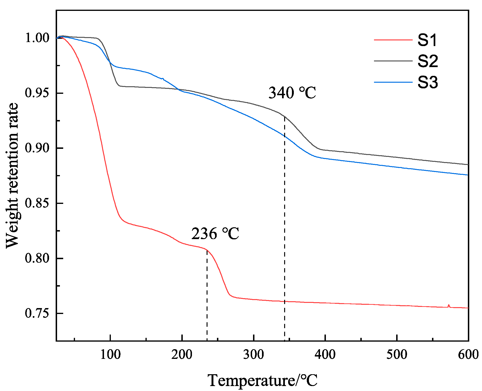
2.4. TGA
2.5. SEM and TEM
2.6. Analysis of Zeta Potential
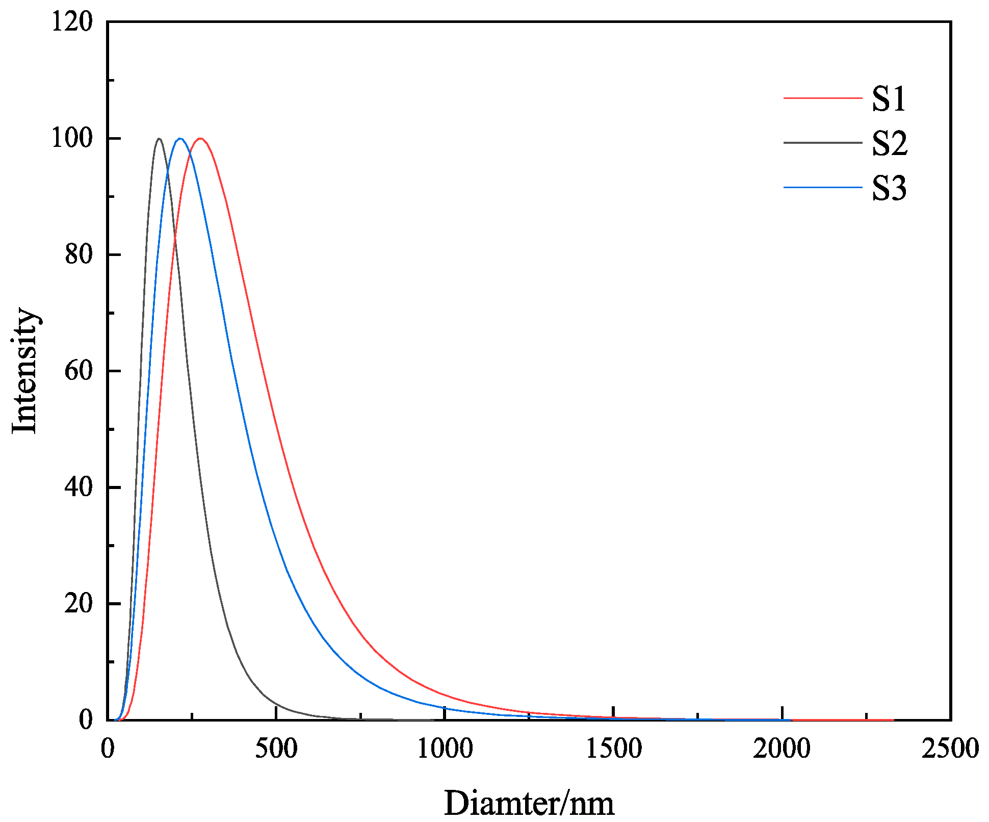
2.7. Particle Size Measurement
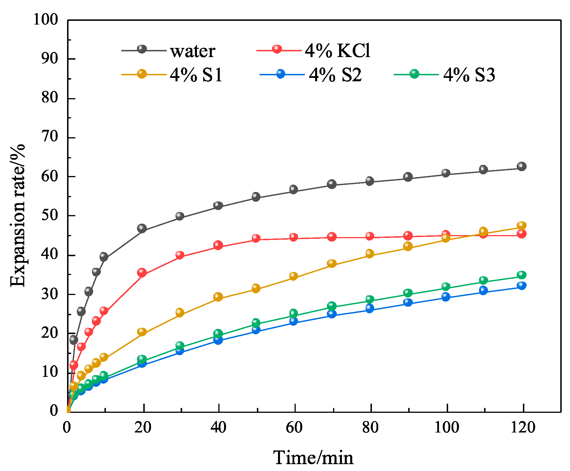
2.8. Linear Expansion Experiment on MMHlc
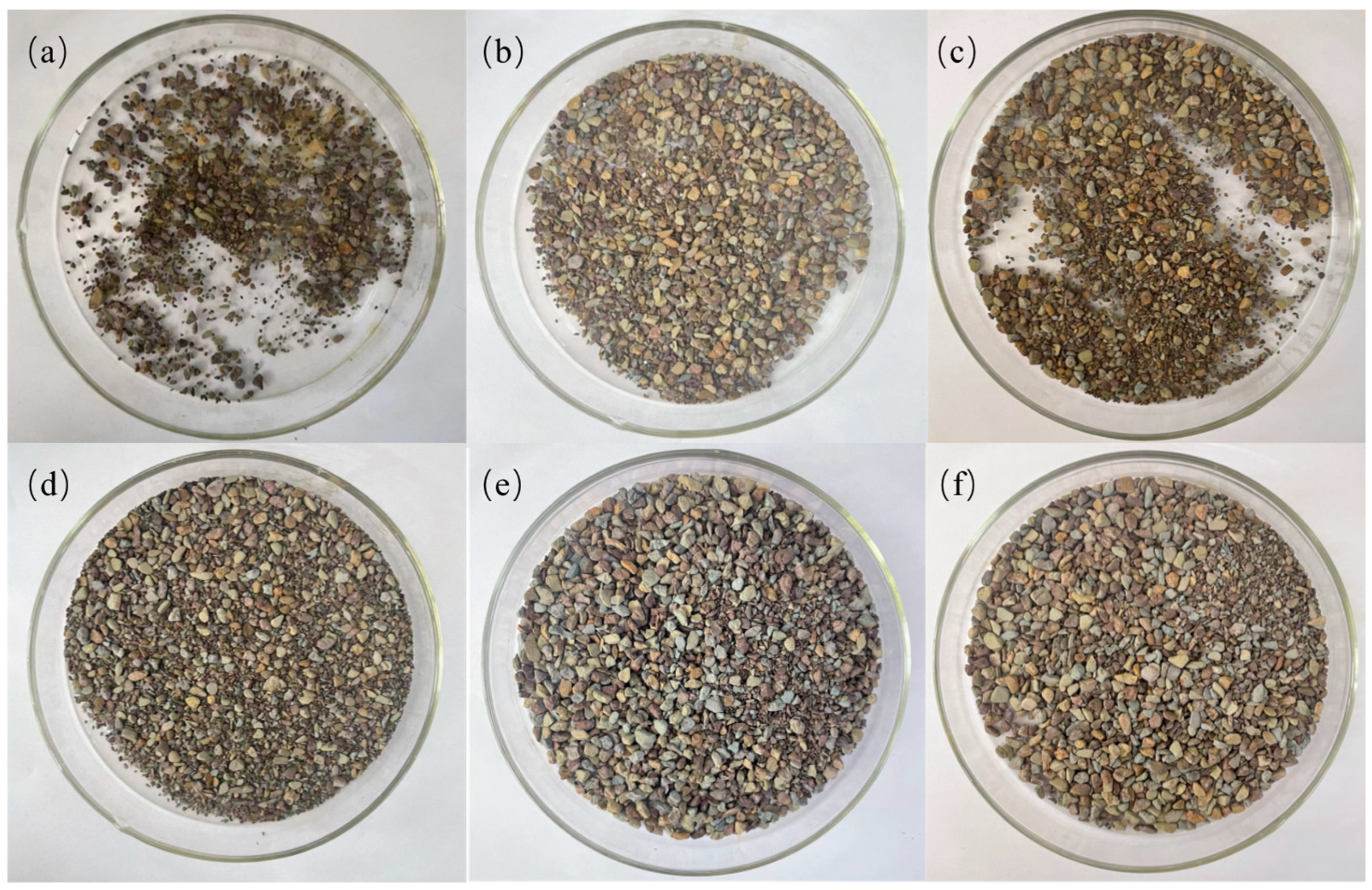
2.9. Experimental Analysis of Shale Rolling Recovery
2.10. Mechanism Discussion
3. Conclusions
4. Materials and Methods
4.1. Materials
4.2. Synthesis of MMHlc
4.3. X-ray Diffraction
4.4. FTIR Spectroscopy
4.5. TGA
4.6. TEM and SEM
4.7. Zeta and Particle Size Experiment
4.8. Drilling Fluid Performance Evaluation
4.9. Rolling Recovery Experiment
4.10. Inhibitory Evaluation
Author Contributions
Funding
Institutional Review Board Statement
Informed Consent Statement
Data Availability Statement
Acknowledgments
Conflicts of Interest
References
- Yuan, S.; Wang, Q. New progress and prospect of oilfields development technologies in China. Pet. Explor. Dev. 2018, 45, 698–711. [Google Scholar] [CrossRef]
- Burba, J.L.; Holman, W.E.; Crabb, C.R. Laboratory and Field Evalutions of Novel Inorganic Drilling Fluid Additive. IADC/SPE Drill. Conf. 1988, 6, SPE-17198. [Google Scholar] [CrossRef]
- Gao, Y.; Liu, X.; Yang, G. Amorphous mixed-metal hydroxide nanostructures for advanced water oxidation catalysts. Nanoscale 2016, 8, 5015–5023. [Google Scholar] [CrossRef] [PubMed]
- Akkouche, A.; Benmounah, A.; Gueciouer, A.; Chalah, K. Valorization of mixed metal hydroxide on Algerian Na-Bentonite suspensions: Application to water-based drilling fluid. Egypt. J. Pet. 2020, 29, 127–131. [Google Scholar] [CrossRef]
- Zhang, B.; Wang, Q.; Wei, Y.; Wei, W.; Du, W.; Zhang, J.; Chen, G.; Slaný, M. Preparation and Swelling Inhibition of Mixed Metal Hydroxide to Bentonite Clay. Minerals 2022, 12, 459. [Google Scholar] [CrossRef]
- Zhang, B.; Wang, Q.; Du, W.; Li, Y.; Zhang, J.; Zhang, J.; Matejdes, M.; Slaný, M.; Gang, C. Multi-Mixed Metal Hydroxide as a Strong Stratigraphic Nanoclay Inhibitor in Solid-Free Drilling Fluid. Nanomaterials 2022, 12, 3863. [Google Scholar] [CrossRef]
- Han, S.-H.; Zhang, C.-G.; Hou, W.-G.; Sun, D.-J.; Wang, G.-T. Study on the preparation and structure of positive sol composed of mixed metal hydroxide. Colloid Polym. Sci. 1996, 274, 860–865. [Google Scholar] [CrossRef]
- Vryzas, Z.; Kelessidis, V.C. Nano-based drilling fluids: A review. Energies 2017, 10, 540. [Google Scholar] [CrossRef]
- Karakosta, K.; Mitropoulos, A.C.; Kyzas, G.Z. A review in nanopolymers for drilling fluids applications. J. Mol. Struct. 2021, 1227, 129702. [Google Scholar] [CrossRef]
- Zhuang, G.; Zhang, Z.; Peng, S.; Gao, J.; Pereira, F.A.; Jaber, M. The interaction between surfactants and montmorillonite and its influence on the properties of organo-montmorillonite in oil-based drilling fluids. Clays Clay Miner. 2019, 67, 190–208. [Google Scholar] [CrossRef]
- Li, P.; Liu, M.; Feng, J.; Hui, B.; Hu, M.; Guo, J. Copolymer intercalated hydrotalcite sustained release-type fluid loss additive for water-based drilling fluid: Synthesis, characterization, and performance evaluation. Colloids Surf. A Physicochem. Eng. Asp. 2023, 669, 131451. [Google Scholar] [CrossRef]
- Wan-Guo, H.; De-Jun, S.; Shu-Hua, H.; Chun-Guang, Z.; Guo-Ting, W. Study on the thixotropy of aluminum magnesium hydroxide–Na-montmorillonite suspension. Colloid Polym. Sci. 1998, 276, 274–277. [Google Scholar] [CrossRef]
- Hou, W.-G.; Jiang, P.; Han, S.-H.; Hu, J.-F.; Li, D.-Q. Studies on zero point of charge and intrinsic ionization constant of Zn− Mg− Al hydrotalcite-like compounds. Colloid Polym. Sci. 2003, 281, 738–744. [Google Scholar] [CrossRef]
- Li, J.; Wang, Z. High temperature solid-free drilling fluid technology. Drill. Fluid Complet. Fluid 2017, 34, 11–15. [Google Scholar] [CrossRef]
- Liang, X.; Zang, Y.; Xu, Y.; Tan, X.; Hou, W.; Wang, L.; Sun, Y. Sorption of metal cations on layered double hydroxides. Colloids Surf. A Physicochem. Eng. Asp. 2013, 433, 122–131. [Google Scholar] [CrossRef]
- Tan, L.; Yu, J.; Wang, C.; Wang, H.; Liu, X.; Gao, H.; Xin, L.; Liu, D.; Hou, W.; Zhan, T. Partial sulfidation strategy to NiFe-LDH@ FeNi2S4 heterostructure enable high-performance water/seawater oxidation. Adv. Funct. Mater. 2022, 32, 2200951. [Google Scholar] [CrossRef]
- Du, W.; Slaný, M.; Wang, X.; Chen, G.; Zhang, J. The inhibition property and mechanism of a novel low molecular weight zwitterionic copolymer for improving wellbore stability. Polymers 2020, 12, 708. [Google Scholar] [CrossRef]
- Du, W.; Wang, X.; Chen, G.; Zhang, J.; Slaný, M. Synthesis, property and mechanism analysis of a novel polyhydroxy organic amine shale hydration inhibitor. Minerals 2020, 10, 128. [Google Scholar] [CrossRef]
- Wang, Q.; Slaný, M.; Gu, X.; Miao, Z.; Du, W.; Zhang, J.; Gang, C. Lubricity and rheological properties of highly dispersed graphite in clay-water-based drilling fluids. Materials 2022, 15, 1083. [Google Scholar] [CrossRef]
- Jing, Y.; Zhang, J.; Hu, W.; Du, W.; Xie, J.; Qu, C.; Chen, G. Preparation and Evaluation of Ammonium-Succinic salts as shale swelling inhibitor and its application in water-based drilling fluids. Russ. J. Phys. Chem. B 2021, 15, S102–S108. [Google Scholar] [CrossRef]
- Liu, X.X.; Gao, L.; Wang, Q.C.; Du, W.C.; Gu, X.F.; Chen, G.; Zhang, J. Evaluation and application of PEG as lubricant in water-based drilling fluid for horizontal well in Sulige Gas Field. Polym. Int. 2021, 70, 83–89. [Google Scholar] [CrossRef]
- Baruah, B.; Mishra, M.; Bhattacharjee, C.R.; Nihalani, M.C.; Mishra, S.K.; Baruah, S.D.; Phukan, P.; Goswamee, R.J. The effect of particle size of clay on the viscosity build up property of mixed metal hydroxides (MMH) in the low solid-drilling mud compositions. Appl. Clay Sci. 2013, 80, 169–175. [Google Scholar] [CrossRef]
- Chen, G.; Yan, J.; Li, L.L.; Zhang, J.; Gu, X.F.; Song, H. Preparation and performance of amine-tartaric salt as potential clay expansion inhibitor. Appl. Clay Sci. 2017, 138, 12–16. [Google Scholar] [CrossRef]
- Zhang, R.J.; Gao, L.; Du, W.C.; Hu, W.M.; Duan, W.G.; Gu, X.F.; Zhang, J.; Chen, G. The application of ferric chloride-lignin sulfonate as shale inhibitor in water-based drilling fluid. Molecules 2019, 24, 4331. [Google Scholar] [CrossRef] [PubMed]
- Slaný, M.; Jankovič, Ľ.; Madejová, J. Structural characterization of organo-montmorillonites prepared from a series of primary alkylamines salts: Mid-IR and near-IR study. Appl. Clay Sci. 2019, 176, 11–20. [Google Scholar] [CrossRef]
- Lee, H.; Lee, H.B.; Kwon, S.; Salmeron, M. Internal and external atomic steps in graphite exhibit dramatically different phys-ical and chemical properties. ACS Nano 2015, 9, 3814–3819. [Google Scholar] [CrossRef]
- Xiao, D.; Hu, Y.; Wang, Y.; Deng, H.; Zhang, J.; Tang, B.; Xi, J.; Tang, S.; Li, G. Wellbore cooling and heat energy utilization method for deep shale gas horizontal well drilling. Appl. Therm. Eng. 2022, 213, 118684. [Google Scholar] [CrossRef]
- Zhao, G.; Shi, L.; Yang, G.; Zhuang, X.; Cheng, B. 3D fibrous aerogels from 1D polymer nanofibers for energy and environmental applications. J. Mater. Chem. A 2023, 11, 512–547. [Google Scholar] [CrossRef]
- Chen, Y.; Li, J.; Lu, J.; Ding, M.; Chen, Y. Synthesis and properties of poly (vinyl alcohol) hydrogels with high strength and toughness. Polym. Test. 2022, 108, 107516. [Google Scholar] [CrossRef]
- Yuan, Y.; Zhao, H.; Xv, W.; Zhang, D.; Wang, Z.; Li, H.; Qin, Y.; Li, S.; Lai, J.; Wang, L. Noble metal aerogels rapidly synthesized by ultrasound for electrocatalytic reaction. Chin. Chem. Lett. 2022, 33, 2021–2025. [Google Scholar] [CrossRef]
- Fu, Y.; Pan, Q.; Liu, G.; Zhang, G. Gradient structure of Ti-55531 with nano-ultrafine grains fabricated by simulation and suction casting. J. Mater. Eng. Perform. 2023, 32, 3084–3093. [Google Scholar] [CrossRef]


| Temperature | Recipe | AV/ mPa·s | PV/ mPa·s | YP/ Pa | FL/ mL | Lubricity Factor | YP/PV |
|---|---|---|---|---|---|---|---|
| 25 °C | 4% base mud | 5.05 | 4.80 | 0.25 | 48.5 | 0.23 | 0.05 |
| 4% S1 | 6.05 | 2.00 | 4.05 | 13.5 | 0.25 | 2.03 | |
| 4% S2 | 6.60 | 2.10 | 4.50 | 16.7 | 0.27 | 2.14 | |
| 4% S3 | 7.75 | 3.00 | 4.75 | 22.1 | 0.22 | 1.58 | |
| 250 °C | 4% base mud | 2.75 | 2.70 | 0.05 | 150.0 | / | 0.02 |
| 4% S1 | 5.70 | 2.00 | 3.70 | 67.5 | 0.14 | 1.85 | |
| 4% S2 | 5.25 | 1.90 | 3.35 | 45.6 | 0.15 | 1.76 | |
| 4% S3 | 3.00 | 1.50 | 1.50 | 62.1 | 0.11 | 1.00 |
| Name | Zeta Potential Value/mV |
|---|---|
| 4% S1 | 41.23 (± 1.71) |
| 4% S2 | 52.16 (± 2.12) |
| 4% S3 | 39.13 (± 0.96) |
| Name | Average Particle Size/nm | Median Particle Size/nm |
|---|---|---|
| 4% S1 | 345.2 (± 3.1) | 378.1 (± 2.7) |
| 4% S2 | 178.5 (± 4.6) | 165.4 (± 3.3) |
| 4% S3 | 432.1 (± 3.7) | 446.1 (± 1.7) |
| Name | First Rolling Recovery | Second Rolling Recovery |
|---|---|---|
| Water | 9.8% (± 1.2) | 8.4% (± 1.0) |
| 7% KCl | 23.8% (± 2.2) | 21.1% (± 0.7) |
| 4% Base mud | 15.6% (± 1.6) | 14.4% (± 1.2) |
| 4% S1 | 50.2% (± 4.1) | 48.7% (± 2.7) |
| 4% S2 | 66.0% (± 3.6) | 64.1% (± 1.9) |
| 4% S3 | 37.0% (± 2.7) | 30.1% (± 2.1) |
| Name | nMg:nAl:nFe | Precipitant | Product Status |
|---|---|---|---|
| S1 | 3:1:1 | Na2CO3 | Gel |
| S2 | 3:1:1 | Na2SiO3 | Gel |
| S3 | 3:1:1 | C17H33CO2Na | Gel |
Disclaimer/Publisher’s Note: The statements, opinions and data contained in all publications are solely those of the individual author(s) and contributor(s) and not of MDPI and/or the editor(s). MDPI and/or the editor(s) disclaim responsibility for any injury to people or property resulting from any ideas, methods, instructions or products referred to in the content. |
© 2023 by the authors. Licensee MDPI, Basel, Switzerland. This article is an open access article distributed under the terms and conditions of the Creative Commons Attribution (CC BY) license (https://creativecommons.org/licenses/by/4.0/).
Share and Cite
Zhang, B.; Wang, Q.; Chang, X.; Du, W.; Zhang, F.; Kuruc, M.; Slaný, M.; Chen, G. Use of Highly Dispersed Mixed Metal Hydroxide Gel Compared to Bentonite Based Gel for Application in Drilling Fluid under Ultra-High Temperatures. Gels 2023, 9, 513. https://doi.org/10.3390/gels9070513
Zhang B, Wang Q, Chang X, Du W, Zhang F, Kuruc M, Slaný M, Chen G. Use of Highly Dispersed Mixed Metal Hydroxide Gel Compared to Bentonite Based Gel for Application in Drilling Fluid under Ultra-High Temperatures. Gels. 2023; 9(7):513. https://doi.org/10.3390/gels9070513
Chicago/Turabian StyleZhang, Bowen, Qingchen Wang, Xiaofeng Chang, Weichao Du, Fan Zhang, Michal Kuruc, Michal Slaný, and Gang Chen. 2023. "Use of Highly Dispersed Mixed Metal Hydroxide Gel Compared to Bentonite Based Gel for Application in Drilling Fluid under Ultra-High Temperatures" Gels 9, no. 7: 513. https://doi.org/10.3390/gels9070513
APA StyleZhang, B., Wang, Q., Chang, X., Du, W., Zhang, F., Kuruc, M., Slaný, M., & Chen, G. (2023). Use of Highly Dispersed Mixed Metal Hydroxide Gel Compared to Bentonite Based Gel for Application in Drilling Fluid under Ultra-High Temperatures. Gels, 9(7), 513. https://doi.org/10.3390/gels9070513