
Hydrate-Based Methane Storage in Biodegradable Hydrogels Absorbing Dilute Sodium P-Styrenesulfonate Solution


Abstract

1. Introduction
2. Results and Discussion
2.1. Methane Hydrate Formation Kinetics in Hydrogel-SS Hybrid Medium
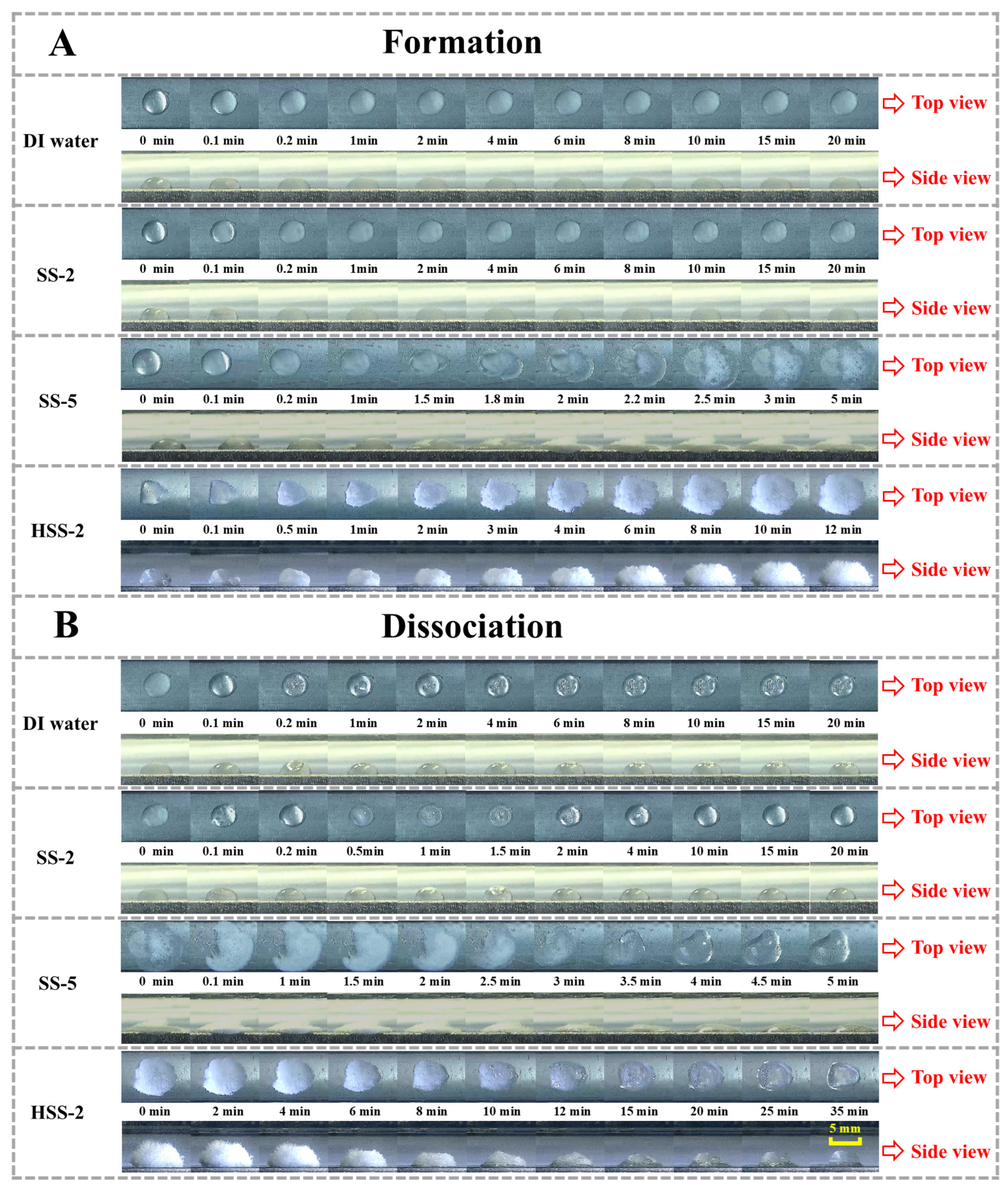
2.2. Morphological Evolutions of Hydrate Formation and Dissociation
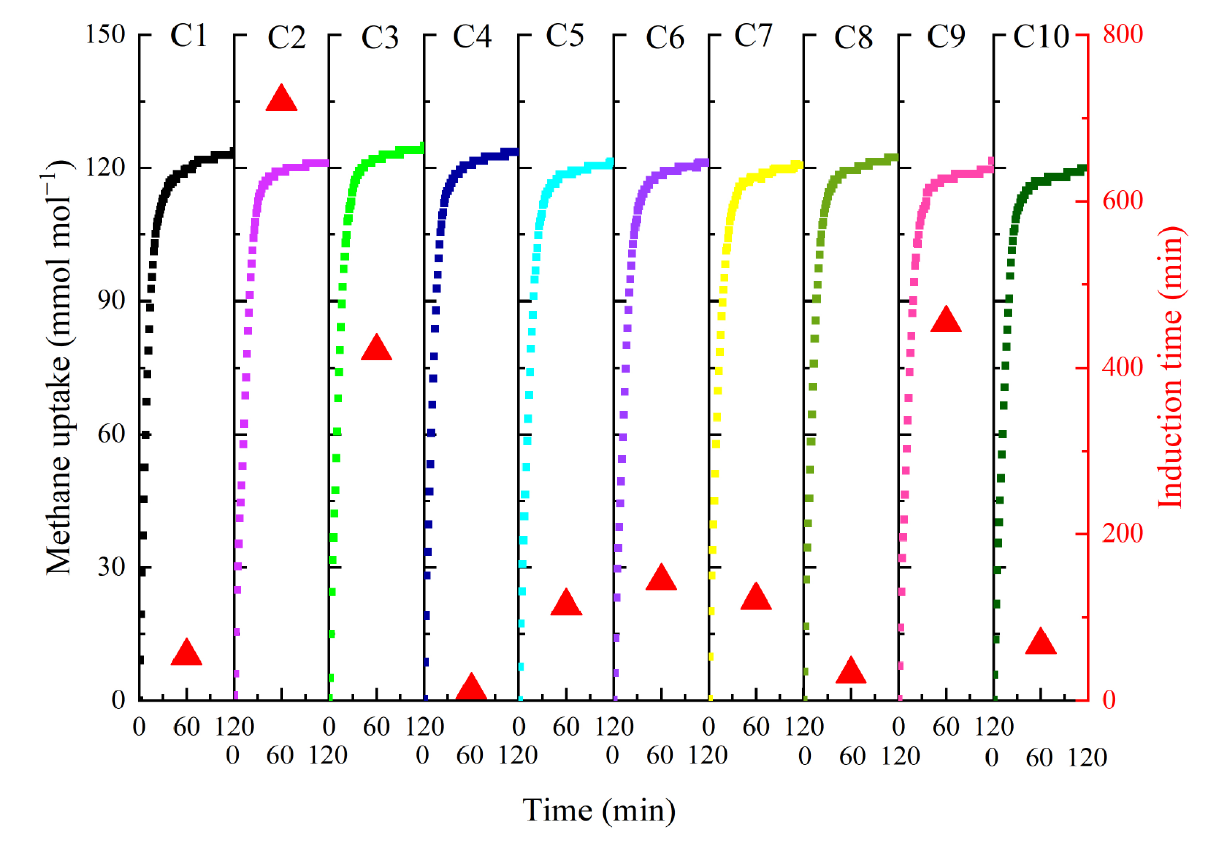
2.3. Recycling Performance
3. Conclusions
4. Materials and Methods
4.1. Materials
4.2. Methane Hydrate Formation in Hydrogel-SS Hybrid Medium
4.3. Morphology Observation of Hydrate Formation and Dissociation
4.3.1. Stacked Hydrogels Absorbing Dilute SS
4.3.2. Single-Grained Hydrogel Particle Absorbing Dilute SS
4.4. Cryo-Electron Microscopy Observation
4.5. Recyclability Tests
Author Contributions
Funding
Institutional Review Board Statement
Informed Consent Statement
Data Availability Statement
Conflicts of Interest
References
- Mimachi, H.; Takeya, S.; Yoneyama, A.; Hyodo, K.; Takeda, T.; Gotoh, Y.; Murayama, T. Natural gas storage and transportation within gas hydrate of smaller particle: Size dependence of self-preservation phenomenon of natural gas hydrate. Chem. Eng. Sci. 2014, 118, 208–213. [Google Scholar] [CrossRef]
- Demirbas, A. Methane Gas Hydrate; Springer: London, UK, 2010; ISBN 978-1-84882-871-1. [Google Scholar]
- Lu, Y.-Y.; Ge, B.-B.; Zhong, D.-L. Investigation of using graphite nanofluids to promote methane hydrate formation: Application to solidified natural gas storage. Energy 2020, 199, 117424. [Google Scholar] [CrossRef]
- Veluswamy, H.P.; Kumar, A.; Seo, Y.; Lee, J.D.; Linga, P. A review of solidified natural gas (SNG) technology for gas storage via clathrate hydrates. Appl. Energy 2018, 216, 262–285. [Google Scholar] [CrossRef]
- Fan, S.; Wang, Y.; Wang, Y.; Lang, X.; Wang, S. Design and optimization of offshore ship-based natural gas storage technologies in the South China Sea. Energy Convers. Manag. 2021, 239, 114218. [Google Scholar] [CrossRef]
- Mimachi, H.; Takahashi, M.; Takeya, S.; Gotoh, Y.; Yoneyama, A.; Hyodo, K.; Takeda, T.; Murayama, T. Effect of Long-Term Storage and Thermal History on the Gas Content of Natural Gas Hydrate Pellets under Ambient Pressure. Energy Fuels 2015, 29, 4827–4834. [Google Scholar] [CrossRef]
- Lin, W.; Xiong, X.; Gu, A. Optimization and thermodynamic analysis of a cascade PLNG (pressurized liquefied natural gas) process with CO2 cryogenic removal. Energy 2018, 161, 870–877. [Google Scholar] [CrossRef]
- Hao, W.; Wang, J.; Fan, S.; Hao, W. Evaluation and analysis method for natural gas hydrate storage and transportation processes. Energy Convers. Manag. 2008, 49, 2546–2553. [Google Scholar] [CrossRef]
- Deng, Z.; Wang, Y.; Yu, C.; Li, G.; Lang, X.; Wang, S.; Fan, S. Promoting methane hydrate formation with expanded graphite additives: Application to solidified natural gas storage. Fuel 2021, 299, 120867. [Google Scholar] [CrossRef]
- Veluswamy, H.P.; Kumar, S.; Kumar, R.; Rangsunvigit, P.; Linga, P. Enhanced clathrate hydrate formation kinetics at near ambient temperatures and moderate pressures: Application to natural gas storage. Fuel 2016, 182, 907–919. [Google Scholar] [CrossRef]
- Nguyen, N.N.; Nguyen, A.V. “Nanoreactors” for Boosting Gas Hydrate Formation toward Energy Storage Applications. ACS Nano 2022, 16, 11504–11515. [Google Scholar] [CrossRef]
- Xiao, P.; Li, J.-J.; Chen, W.; Pang, W.-X.; Peng, X.-W.; Xie, Y.; Wang, X.-H.; Deng, C.; Sun, C.-Y.; Liu, B.; et al. Enhanced formation of methane hydrate from active ice with high gas uptake. Nat. Commun. 2023, 14, 8068. [Google Scholar] [CrossRef] [PubMed]
- Qureshi, M.F.; Atilhan, M.; Altamash, T.; Aparicio, S.; Aminnaji, M.; Tohidi, B. High-pressure gas hydrate autoclave hydraulic experiments and scale-up modeling on the effect of stirring RPM effect. J. Nat. Gas Sci. Eng. 2017, 38, 50–58. [Google Scholar] [CrossRef]
- Lv, Q.-N.; Li, X.-S.; Xu, C.-G.; Chen, Z.-Y. Experimental Investigation of the Formation of Cyclopentane-Methane Hydrate in a Novel and Large-Size Bubble Column Reactor. Ind. Eng. Chem. Res. 2012, 51, 5967–5975. [Google Scholar] [CrossRef]
- Ganji, H.; Manteghian, M.; Sadaghiani zadeh, K.; Omidkhah, M.R.; Rahimi Mofrad, H. Effect of different surfactants on methane hydrate formation rate, stability and storage capacity. Fuel 2007, 86, 434–441. [Google Scholar] [CrossRef]
- Okutani, K.; Kuwabara, Y.; Mori, Y.H. Surfactant effects on hydrate formation in an unstirred gas/liquid system: An experimental study using methane and sodium alkyl sulfates. Chem. Eng. Sci. 2008, 63, 183–194. [Google Scholar] [CrossRef]
- Sadeh, E.; Farhadian, A.; Mohammadi, A.; Maddah, M.; Pourfath, M.; Yang, M. Energy-efficient storage of methane and carbon dioxide capture in the form of clathrate hydrates using a novel non-foaming surfactant: An experimental and computational investigation. Energy Convers. Manag. 2023, 293, 117475. [Google Scholar] [CrossRef]
- Govindaraj, V.; Mech, D.; Pandey, G.; Nagarajan, R.; Sangwai, J.S. Kinetics of methane hydrate formation in the presence of activated carbon and nano-silica suspensions in pure water. J. Nat. Gas Sci. Eng. 2015, 26, 810–818. [Google Scholar] [CrossRef]
- Denning, S.; Majid, A.A.; Crawford, J.M.; Wells, J.D.; Carreon, M.A.; Koh, C.A. Methane storage scale-up using hydrates & metal organic framework HKUST-1 in a packed column. Fuel 2022, 325, 124920. [Google Scholar] [CrossRef]
- Qin, Y.; Bao, R.; Shang, L.; Zhou, L.; Liu, Z. Growth and occurrence characteristics of methane hydrate in a complex system of silica sand and sodium dodecyl sulfate. Chem. Eng. Sci. 2022, 249, 117349. [Google Scholar] [CrossRef]
- Zhou, L.; Sun, Y.; Zhou, Y. Enhancement of the methane storage on activated carbon by preadsorbed water. AIChE J. 2002, 48, 2412–2416. [Google Scholar] [CrossRef]
- Choudhury, N.A.; Sampath, S.; Shukla, A.K. Hydrogel-polymer electrolytes for electrochemical capacitors: An overview. Energy Environ. Sci. 2009, 2, 55–67. [Google Scholar] [CrossRef]
- Shahshahani, S.; Shahgholi, M.; Karimipour, A. The thermal performance and mechanical stability of methacrylic acid porous hydrogels in an aqueous medium at different initial temperatures and hydrogel volume fraction using the molecular dynamics simulation. J. Mol. Liq. 2023, 382, 122001. [Google Scholar] [CrossRef]
- Ding, A.; Yang, L.; Fan, S.; Lou, X. Reversible methane storage in porous hydrogel supported clathrates. Chem. Eng. Sci. 2013, 96, 124–130. [Google Scholar] [CrossRef]
- Shi, B.-H.; Yang, L.; Fan, S.-S.; Lou, X. An investigation on repeated methane hydrates formation in porous hydrogel particles. Fuel 2017, 194, 395–405. [Google Scholar] [CrossRef]
- Wang, F.; Song, F.-P.; Li, C.; Sun, M.-T. Promoted methane hydrate formation in -SO3−-rich hydrogel clathrate. Fuel 2022, 323, 124398. [Google Scholar] [CrossRef]
- Wang, F.; Song, F.-P.; Li, C.; Sun, M.-T. Preparation of a Hydrogel-Based Promoter for Methane Hydrate Formation: Effects of −SO 3– Density on Promotion Efficiency. Energy Fuels 2022, 36, 2731–2738. [Google Scholar] [CrossRef]
- Li, C.; Tan, K.; Hua, F.; Wang, C.; Sun, M.; Wang, F.; Wang, X. Eco-friendly hydrogels serving as water carriers for improving methane hydrate formation and dissociation processes. Fuel 2024, 362, 130854. [Google Scholar] [CrossRef]
- Li, C.; Tan, K.; Hua, F.; Wang, C.; Wang, X.; Wang, F.; Sun, M. Methane hydrate formation promoted by eco-friendly hydrogels carrying with trace SDS. Fuel 2025, 380, 133107. [Google Scholar] [CrossRef]
- Yoslim, J.; Linga, P.; Englezos, P. Enhanced growth of methane–propane clathrate hydrate crystals with sodium dodecyl sulfate, sodium tetradecyl sulfate, and sodium hexadecyl sulfate surfactants. J. Cryst. Growth 2010, 313, 68–80. [Google Scholar] [CrossRef]
- Bhattacharjee, G.; Linga, P. Amino Acids as Kinetic Promoters for Gas Hydrate Applications: A Mini Review. Energy Fuels 2021, 35, 7553–7571. [Google Scholar] [CrossRef]
- Toledo, P.V.O.; Bernardinelli, O.D.; Sabadini, E.; Petri, D.F.S. The states of water in tryptophan grafted hydroxypropyl methylcellulose hydrogels and their effect on the adsorption of methylene blue and rhodamine B. Carbohydr. Polym. 2020, 248, 116765. [Google Scholar] [CrossRef]


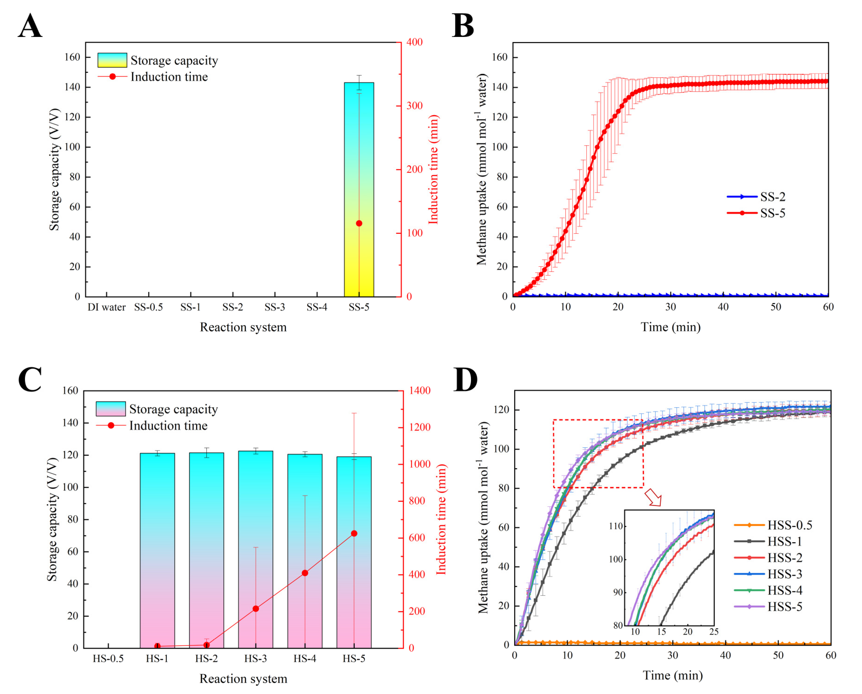
| Group | Induction Time (min) | HGRt90 (mmol mL−1 min−1) | Methane Uptake (mmol mol−1) | Storage Capacity (v/v) |
|---|---|---|---|---|
| DI water | Undetected | - | - | - |
| SS-0.5 | Undetected | - | - | - |
| SS-1 | Undetected | - | - | - |
| SS-2 | Undetected | - | - | - |
| SS-3 | Undetected | - | - | - |
| SS-4 | Undetected | - | - | - |
| SS-5 | 115.8 ± 203.8 | 0.380 ± 0.075 | 144.4 ± 4.9 | 143.1 ± 4.9 |
| HSS-0.5 | Undetected | - | - | - |
| HSS-1 | 11.3 ± 16.3 | 0.184 ± 0.006 | 122.3 ± 1.6 | 121.2 ± 1.6 |
| HSS-2 | 18.7 ± 32.3 | 0.250 ± 0.004 | 122.6 ± 3.1 | 121.5 ± 3.1 |
| HSS-3 | 216.0 ± 332.6 | 0.296 ± 0.053 | 123.7 ± 1.9 | 122.6 ± 1.9 |
| HSS-4 | 410.0 ± 420.4 | 0.292 ± 0.021 | 121.7 ± 1.6 | 120.6 ± 1.6 |
| HSS-5 | 625.3 ± 653.2 | 0.306 ± 0.023 | 120.1 ± 1.8 | 119.1 ± 1.8 |
| Liquid Type | AC (g g−1) |
|---|---|
| Distilled water | 330.7 ± 8.4 |
| 0.5 mmol L−1 of SS solution | 292.5 ± 4.8 |
| 1 mmol L−1 of SS solution | 251.9 ± 6.2 |
| 2 mmol L−1 of SS solution | 203.9 ± 2.3 |
| 3 mmol L−1 of SS solution | 189.3 ± 3.1 |
| 4 mmol L−1 of SS solution | 175.5 ± 5.6 |
| 5 mmol L−1 of SS solution | 151.1 ± 9.7 |
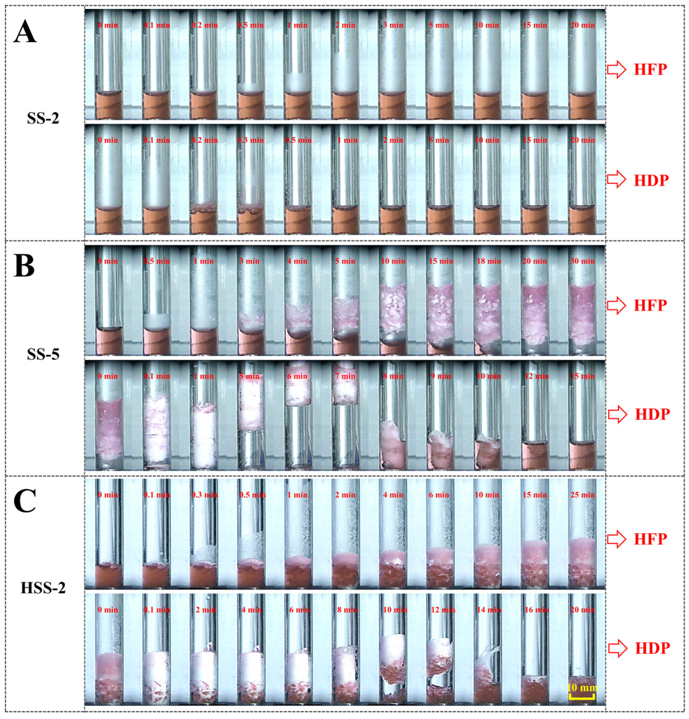
| Reaction System | Hydrate Height Increment (mm) | EC |
|---|---|---|
| SS-5 | 16.1 ± 0.9 | 1.847 |
| HSS-2 | 8.2 ± 1.4 | 1.109 |
| Number of Cycles | Induction Time (min) | HGRt90 (mmol mL−1 min−1) | Methane Uptake (mmol mol−1) | Storage Capacity (v/v) |
|---|---|---|---|---|
| C1 | 54 | 0.229 | 123.92 | 122.82 |
| C2 | 720 | 0.219 | 121.67 | 120.00 |
| C3 | 420 | 0.223 | 125.06 | 123.96 |
| C4 | 13 | 0.241 | 123.64 | 122.55 |
| C5 | 114 | 0.215 | 121.50 | 120.43 |
| C6 | 144 | 0.205 | 120.98 | 119.91 |
| C7 | 121 | 0.218 | 120.61 | 119.54 |
| C8 | 32 | 0.229 | 122.43 | 121.34 |
| C9 | 454 | 0.203 | 121.62 | 120.54 |
| C10 | 67 | 0.215 | 119.97 | 118.91 |
| Group | Hydrogel | Liquid |
|---|---|---|
| DI water | - | 10 mL of distilled water |
| SS-0.5 | 0 | 10 mL of 0.5 mmol L−1 SS solution |
| SS-1 | 0 | 10 mL of 1 mmol L−1 SS solution |
| SS-2 | 0 | 10 mL of 2 mmol L−1 SS solution |
| SS-3 | 0 | 10 mL of 3 mmol L−1 SS solution |
| SS-4 | 0 | 10 mL of 4 mmol L−1 SS solution |
| SS-5 | 0 | 10 mL of 5 mmol L−1 SS solution |
| HSS-0.5 | 0.0833 g | 10 mL of 1 mmol L−1 SS solution |
| HSS-1 | 0.0833 g | 10 mL of 2 mmol L−1 SS solution |
| HSS-2 | 0.0833 g | 10 mL of 3 mmol L−1 SS solution |
| HSS-3 | 0.0833 g | 10 mL of 4 mmol L−1 SS solution |
| HSS-4 | 0.0833 g | 10 mL of 5 mmol L−1 SS solution |
| HSS-5 | 0.0833 g | 10 mL of 1 mmol L−1 SS solution |
Disclaimer/Publisher’s Note: The statements, opinions and data contained in all publications are solely those of the individual author(s) and contributor(s) and not of MDPI and/or the editor(s). MDPI and/or the editor(s) disclaim responsibility for any injury to people or property resulting from any ideas, methods, instructions or products referred to in the content. |
© 2024 by the authors. Licensee MDPI, Basel, Switzerland. This article is an open access article distributed under the terms and conditions of the Creative Commons Attribution (CC BY) license (https://creativecommons.org/licenses/by/4.0/).
Share and Cite
Hua, F.; Tan, K.; Lv, J.; Wang, F.; Sun, M. Hydrate-Based Methane Storage in Biodegradable Hydrogels Absorbing Dilute Sodium P-Styrenesulfonate Solution. Gels 2025, 11, 1. https://doi.org/10.3390/gels11010001
Hua F, Tan K, Lv J, Wang F, Sun M. Hydrate-Based Methane Storage in Biodegradable Hydrogels Absorbing Dilute Sodium P-Styrenesulfonate Solution. Gels. 2025; 11(1):1. https://doi.org/10.3390/gels11010001
Chicago/Turabian StyleHua, Fangzheng, Kang Tan, Jingyu Lv, Fei Wang, and Mengting Sun. 2025. "Hydrate-Based Methane Storage in Biodegradable Hydrogels Absorbing Dilute Sodium P-Styrenesulfonate Solution" Gels 11, no. 1: 1. https://doi.org/10.3390/gels11010001
APA StyleHua, F., Tan, K., Lv, J., Wang, F., & Sun, M. (2025). Hydrate-Based Methane Storage in Biodegradable Hydrogels Absorbing Dilute Sodium P-Styrenesulfonate Solution. Gels, 11(1), 1. https://doi.org/10.3390/gels11010001