Data Descriptor

Experimental and Nonlinear Finite Element Analysis Data for an Innovative Buckling Restrained Bracing System to Rehabilitate Seismically Deficient Structures

by
Abdul Saboor Karzad
1,2,
Zaid A. Al-Sadoon
3,
Abdullah Sagheer
3 and
Mohammad AlHamaydeh
1,*
1
Department of Civil Engineering, College of Engineering, American University of Sharjah, Sharjah P.O. Box 26666, United Arab Emirates
2
Department of Civil Engineering, Faculty of Engineering, University of Ottawa, Ottawa, ON K1N 6N5, Canada
3
Civil and Environmental Engineering Department, College of Engineering, University of Sharjah, Sharjah P.O. Box 27272, United Arab Emirates
*
Author to whom correspondence should be addressed.
Data 2022, 7(12), 171; https://doi.org/10.3390/data7120171
Submission received: 2 October 2022 / Revised: 10 November 2022 / Accepted: 20 November 2022 / Published: 28 November 2022

Abstract

:
This article presents experimental data and nonlinear finite element analysis (NLFEA) modeling for an innovative buckling restrained bracing (BRB) system. The data were collected from qualification testing of introduced BRBs per the AISC 341 test provision and finite element modeling. The BRB is made of three parts: core bar, restraining unit, and end units, in which duplicates of three different core bar cross sections (i.e., fully threaded, threaded notched, and smooth shaved) were tested. The BRBs introduced in this research come with innovative end parts, so-called fingers. These fingers provide the longitudinal gap required in every BRB system and simultaneously prevent buckling of the core bar at the end regions at both ends of the BRB sample, thus facilitating an easy core replacement if it gets damaged in the event of an earthquake. The measured parameters were the applied cyclic load and the corresponding displacement. Analysis of the acquired data illustrated an almost symmetric hysteric behavior with a little higher capacity under compression but a noticeable overall ductility of 4. Moreover, finite element modeling data for one type of core bar (fully threaded) were curated. The data presented in this paper will be valuable for fabricating BRBs in practice and further research on the topic considered.
Dataset License: Creative Commons Attribution 4.0 International.

1. Summary

The existence of buildings in earthquake-prone regions without adequate seismic detailing has always been a matter of concern. Researchers and industry professionals have proposed and implemented various retrofitting methods to overcome such concerns. For instance, conventional steel-braced frames (CSBFs) are used to improve the seismic load resistance of buildings. However, such braces mainly fail due to flexural bucking, which implies large cross-sections. The alternative with improvement to this method is the use of a buckling-restrained bracing (BRB) system that exhibits almost symmetric compression-tension load resisting capacity. Japan was one of the first places where BRBs were constructed. BRBs provide a significant energy dissipation mechanism in the occurrence of an earthquake. BRBs are mainly constructed of three components: a core (i.e., to resist the applied load), a restraining part (i.e., to restrain the core from buckling under compression), and end hinges (i.e., to facilitate the installation of BRB). Many researchers investigated the behavior of different types of BRBs with regard to the core material and cross-section [1,2,3,4,5,6,7,8]. The current research focuses on proposing an innovative BRB system and investigating its behavior under cyclic loading protocol as per the AISC 341 qualification test [9].
The BRBs introduced in this research come with innovative end parts, so-called fingers. The fingers allow the interior core steel bar to elongate and shorten while maintaining continuous lateral support against buckling without internal longitudinal gaps. This is the essential difference between the proposed BRB and conventional BRB systems, where internal gaps are required in the non-yielding zone (middle part) to facilitate the shortening of the core under compression. These fingers provide the longitudinal gap required in every BRB system and simultaneously prevent buckling of the core bar at the end regions, thus facilitating an easy core replacement if it gets damaged in the event of an earthquake.
The experimental and finite element modeling data obtained and presented in this paper investigate the behavior of buckling-restrained braces (BRBs) that can be used in designing and manufacturing BRBs for employment in seismic deficient structures. The data were extracted from laboratory experiments and finite element modeling results, which are discussed in detail by authors in a research manuscript titled Replaceable Fuse Buckling-Restrained Brace (BRB): Experimental Cyclic Qualification Testing and NLFEA Modeling [10]. The experiments were conducted on small-scale buckling-restrained braces (BRBs) using an Instron hydraulic actuator. Proper instrumentations such as linear variable displacement transducers (LVDTs) and strain gauges were used during cyclic loading. The BRB specimens were tested under cyclic loading in a displacement control mode with a 0.25 mm/s loading rate. The parameters collected were the load and displacement (stroke). Nonlinear finite element modeling was performed using commercial software (ABAQUS).
Researchers conducting experimental, analytical, and numerical studies on the behavior of BRBs during extreme events will benefit from the data presented in this paper. In addition, the designers and engineers will find the experimental data very useful when dealing with rehabilitating seismic deficient structures. The experimental data presented in this paper can be easily replicated for other BRB lengths/types for practical and research purposes. The BRB has innovative end units called fingers, ensuring full restraining to the core bar along its length. The presented data can be further explored with different material types of core bars and diameters for the proposed BRB. Moreover, the nonlinear finite element analysis (NLFEA) model presented herein can be a good source of additional parametric investigation.

2. Data Description

The presented data in this article were experimentally acquired and modeled using the finite element method. A total of six BRBs (i.e., duplicates of three types of BRB core bars) were tested experimentally and verified numerically. Specific labeling was used to designate each BRB type. Three core bars were used in the tested BRBs: fully-threaded, threaded-notched, and smooth-shaved, as shown in Figure 1. The specimens are labeled according to their core bar type, and diameter, i.e., BRB-12-Th stands for a full threaded core bar diameter of 12 mm (Figure 1a), the threaded notched type was labeled BRB-12-Th-Nd (Figure 1b), and the smooth shave one was labeled BRB-12-Sh (Figure 1c).
The core bar total lengths were 1320 mm for the three types of cross sections: fully threaded along the length, fully threaded but notched in the yielding region (notching of 660 mm in the middle), and smooth bar but shaved in the yielding region (shaving of 660 mm in the middle). The core bars were made of stainless steel (SS) with a diameter of 12 mm. After notching, the yielding area reduced to 49 mm2; the non-reduced region remained at 79 mm2; while the smooth shaved bar was 113 mm2 and 50 mm2, respectively. The buckling restraining unit (outer case) was composed of an inner hollow steel pipe (inside diameter of 13 mm) and an outer steel pipe (inside diameter of 77.9 mm). The gap between the inner and outer pipes was filled with cement grout. In addition, the end units include the hinges and an innovative part called fingers. Fingers are provided to facilitate the core bar’s compression–tension loading without transferring the load to the restraining unit.
Moreover, these fingers provide lateral support for the core bar at both ends longitudinally. In comparison, hinges were designed to connect the BRB in the testing facility. These are required to install the BRB into the structure in practice. Figure 2 and Figure 3 illustrate the BRB components and the assembly of those components, respectively.
Further details of the tested BRBs are included in the Excel file sheet called restraining unit and core bar details. The worksheet provides details of the BRB components (i.e., core bar, restraining unit, and innovative end units). The dimensions and strength of the materials were obtained from coupon tests.
In addition, the experimental data are presented in the Excel file sheets labeled hysteresis, one for each type of BRB. The Excel sheets provide the cyclic loading data and plots showing the hysteresis behavior of the tested BRBs. Figure 4 illustrates the experimental displacement amplitude cycles versus time and the hysteretic axial load versus axial displacement response for the threaded core bar BRB-12-Th.
Moreover, separate tabs in the Excel spreadsheet were created and labeled as stiffness and energy dissipation. The analytical data extracted from the experimental data are represented in the sheet labeled stiffness with the secant stiffness versus displacement plot for the push–pull cycles (compression–tension). The secant stiffness is calculated by dividing the axial force by the corresponding displacement in the test protocol. At a displacement of 4 mm; BRB-12-Th exhibited the highest secant stiffness of 5.8 kN/mm. In addition, the sheet labeled energy dissipation shows the cumulative energy dissipated in kN.mm. The energy dissipation is calculated by finding the cumulative area under the hysteresis curves divided by the corresponding number of cycles. BRB-12-Th dissipated the highest amount of energy (12,412 kN·mm). The core bar’s ultimate elongation capacity in tension and compression was 2.6% strain.

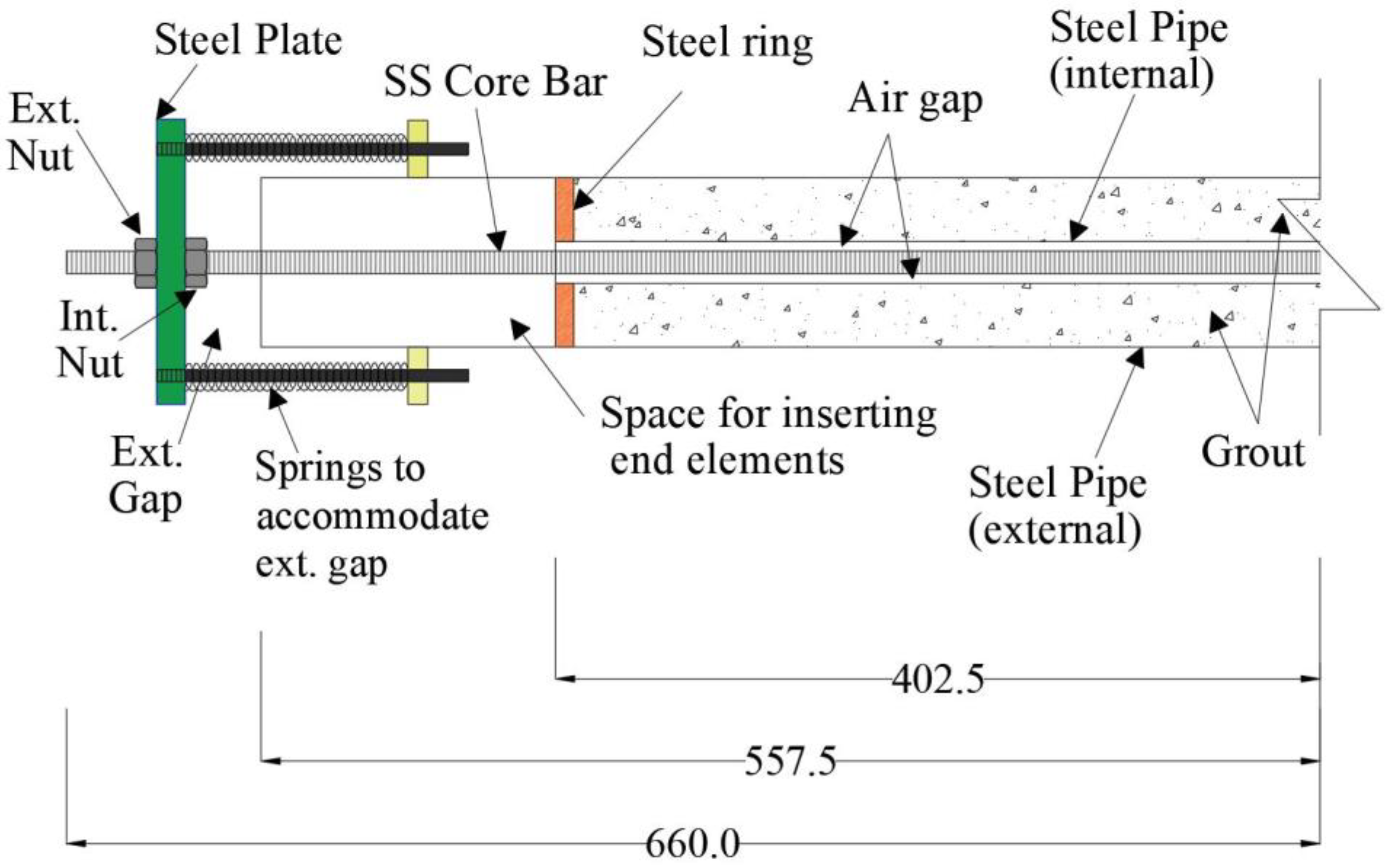
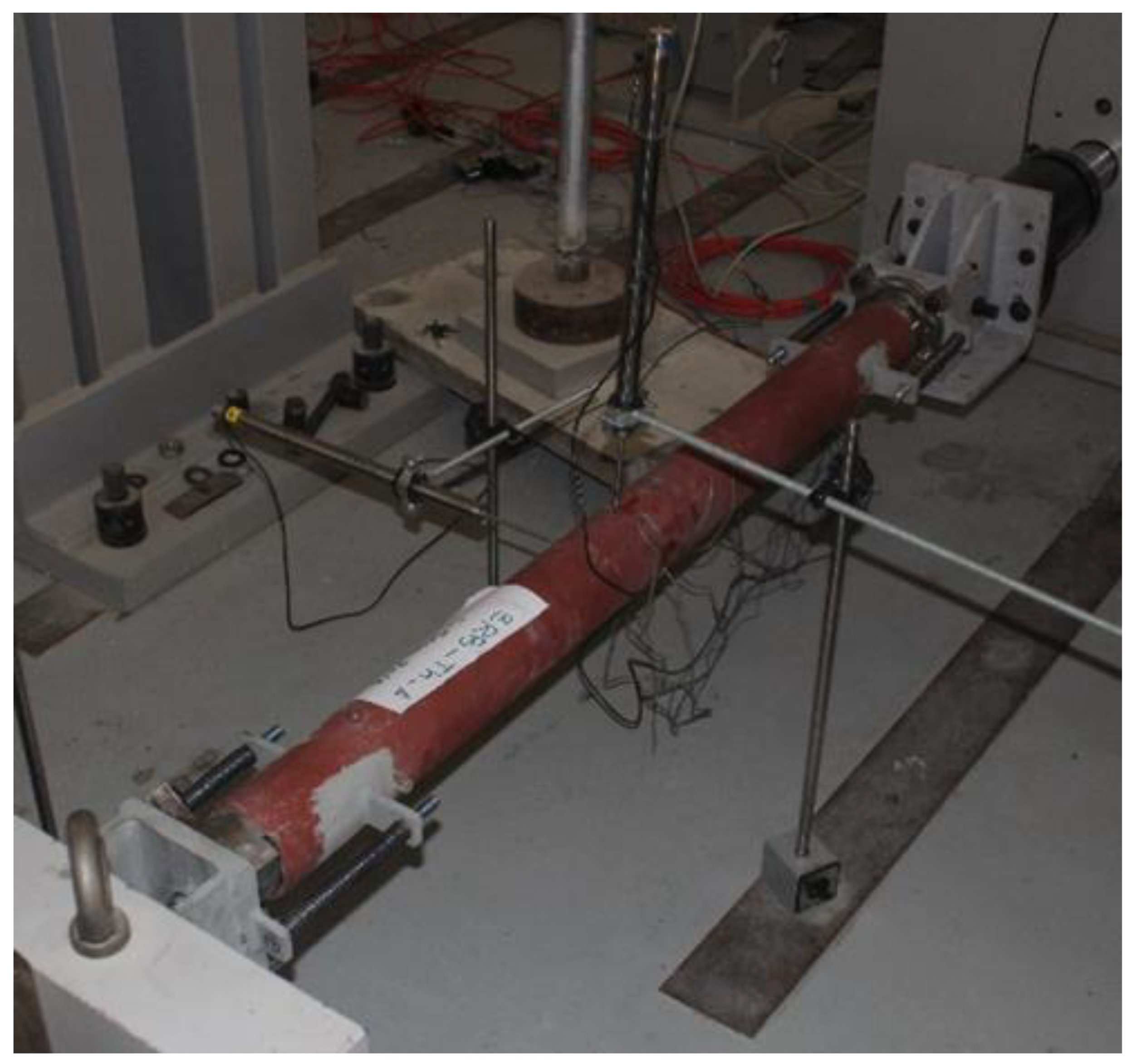
3. Experimental Design, Materials, and Methods

A total of six BRBs were fabricated and tested experimentally, and one of them (threaded bar type) was modeled using the NLFEA method. The BRBs were designed to a 1/3 scale of an actual size BRB to fit the laboratory testing facility. The tested BRBs consisted of three main parts: core bar, restraining unit, and end units. Traditionally, BRBs have the above-mentioned three main components, with different designs and materials as per the literature [1,2,3,4,5,6,7,8,11].
The BRBs were tested according to the AISC 341 [9] qualification test. The qualification test requires a BRB to resist an accumulative inelastic deformation of 200 Δby before failure. The BRBs were tested under uniaxial cyclic loading in a displacement control mode using an Instron hydraulic actuator shown in Figure 5. The figure shows a BRB ready to be tested with the proper data collection and monitoring instrumentation. A displacement–control loading was utilized at a rate of 0.25 mm/s until the passing criteria or the BRB failure were observed. During the test, the BRB went under push–pull cycles of different amplitude (deformation) as per the AISC standard. The core bar is extended in the pull cycle, and no load is transferred to the outer case. Similarly, in the push cycle, only the core bar gets compressed without engaging the outer case in compression, and the novel end units facilitate this mechanism. The outer case is provided only to prevent buckling of the core bar when in compression. The tested BRBs failed in tension after experiencing necking in addition to plastic deformation in the form of local buckling under compression. The all-through threaded bar’s ductility and energy dissipation were higher than the smooth shaved bar. The Excel file sheets labeled hysteresis provide the load levels, actuator loads, and corresponding deformation details. For further insight into the behavior of the tested BRBs, the reader may refer to the related technical article [10].

4. NLFEA Modeling, Assumptions, and Results

The finite element method can be rather valuable when simulating a physical behavior, reducing time, cost, and resources that would otherwise be spent on recreating an actual experiment [12].
The commercial software ABAQUS [13] was used to create the finite element (FE) model and simulate the behavior of the threaded-bar BRB. The model was refined to obtain the results reported in the Excel file. The FE results were highly comparable to the experimental results.
The 3D FE model was created, and the materials’ properties were assigned to the model parts based on the experimental part specifications. Subsequently, the BRB parts were assembled, and the boundary conditions were applied to represent the experimental testing setup. A reference point was created on each BRB end, coupled to the respective surfaces. The first reference point was used to apply the displacement loading protocol, while the other endpoint was fixed completely to prevent movement in all directions and obtain the reaction force. The FE model parts and the corresponding experimental parts are shown in Figure 6.
The core bar had a nominal diameter of 12 mm, including the threads, and the net tensile area was determined based on Equation (1).
Core   Bar   Net   Tensile   Area   =   0.7854   ×   d b     0.9382 n 2
where d b = nominal bolt shank diameter (mm) and n = number of threads/mm.
The net tensile area was calculated to be 80.5 mm2, and the diameter of the bar used in the FE model was 10 mm. Moreover, the element type for all the 3D parts was assigned a hexahedral element with eight nodes of reduced integration (C8D3R). In this case, the integration point lies in the element’s centroid. This research used the enhanced hourglass control approach to alleviate the effect of using under-integrated elements that appear as nonphysical and zero-energy deformations [14,15,16,17]. Using this element type is possible even for thin-walled HSS sections because they were merged with other parts, and more importantly, the bending behavior is dominant in this instance, and 3D elements can represent the stresses better than shell elements.
Additionally, the model accounted for the geometric nonlinearities by conducting a buckling analysis in a separate model to identify the buckling modes (deformed shapes). This was done by choosing the linear perturbation procedure and selecting “Buckle.” Consequently, the first buckling mode was used to create imperfection in the geometry in the initial analysis step and before applying the load.
The material linear and nonlinear properties used in the FE model were obtained from the coupon tests associated with the experimental program. All material properties and modeling parameters can be found in the excel file under the “Modeling properties” tab. The concrete damage plasticity parameters were mainly obtained from the available literature [14] and are presented in Table 1.
It is worth mentioning that all engineering stress–strain curves were converted to true stress–strain curves using Equations (2) and (3), as the NLFEA procedures require them.
σtrue = σeng (1 + εeng)
εtrue = ln(1 + εeng)
where, σ t r u e = true stress value (kN/mm2), σ t r u e = engineered stress value (kN/mm2), ε e n g = engineered strain value, and ε t r u e = true strain value.
However, for the plastic behavior of the steel parts, isotropic hardening was chosen, except for the core bar, where combined hardening was used. Hence, C1 and γ1 were taken as 6.5 GPa and 90, respectively.
Lastly, owing to many factors, quasi-static analysis was also conducted to simulate the experiment using the Explicit solver in ABAQUS [18,19]. To ensure that the ratio of kinetic energy to internal energy is below 5%, an appropriate time step and mass scale factor (MSF) were carefully chosen. Their respective values were chosen, so the effects of the inertial forces were canceled. The best combination of time and MSF was evaluated to be at a time period of 50 s and a scale to a target time increment of 0.00001 s.
Further, mesh sensitivity analysis was conducted to determine the optimal mesh size required to obtain the best possible results without compromising the hardware performance. Based on the comparison of the dissipated energy in the experimental and FE results (as shown in Figure 7), a 10 mm mesh size was selected.
The results obtained from the refined model agreed with the experimental results, as shown in Figure 8, and these results can be found in the Data file under the tab FE model results threaded (TH).
It can be noticed that the NLFEA results are a little off the experimental results in the top-left and bottom-right corners. This can be attributed to the fact that the FE simulation was run for one cycle while the physical experiment ran for many cycles [10]. It is worth noting that required computational resources were a prohibitive obstacle when attempting to model all cycles. This is attributed to the explicit dynamic formulation and the fine mesh necessary to achieve acceptable agreement between the numerical and experimental results.
Lateral loads usually cause damage to structural elements, resulting in the need for rehabilitation. Hence, this innovative BRB system provides a feasible solution for many structural applications, e.g., [20,21,22,23,24]. Moreover, it significantly improves numerous aspects of structural behavior, as described in [25,26,27,28,29,30,31,32,33,34,35,36,37,38,39,40,41,42,43,44,45,46]. Furthermore, cost benefits were reported for several seismic applications [47,48,49,50,51,52,53,54,55,56,57,58].
The experimental results indicated that the introduced innovative BRB system successfully passed the AISC 341 prescribed qualification test protocol. The two successful core bars were the smooth shaved bar in the middle and the all-through threaded bar with a cumulative deformation of 267 Δby and 218 Δby, respectively, before failure. It is worth noting that the experimental and FEA data contained in this manuscript are illustrative samples. The complete dataset is available to the reader in an open-access repository [59].

Author Contributions

A.S.K.: Methodology, Investigation, Data curation, Visualization, Writing—Paper Original draft preparation, Writing—Reviewing and Editing. Z.A.A.-S.: Conceptualization and design, Methodology, Investigation, Writing—Reviewing and Editing, Supervision. A.S.: Methodology, Numerical investigation, Visualization, Software, Writing—Reviewing and Editing. M.A.: Methodology, Numerical investigation, Writing—review & editing, Software, Supervision. All authors have read and agreed to the published version of the manuscript.

Funding

This research was financially supported by the University of Sharjah (UOS) through grant number: 1702040170-P and by the American University of Sharjah (AUS) through the Open Access Program (OAP).

Institutional Review Board Statement

Not applicable.

Informed Consent Statement

Not applicable.

Data Availability Statement

The data published in this paper are available using the following link: http://doi.org/10.5281/zenodo.6795612 (accessed on 5 September 2022).

Acknowledgments

This research was financially supported by the University of Sharjah (UOS) through grant number: 1702040170-P and by the American University of Sharjah (AUS) through the Open Access Program (OAP). The authors greatly appreciate the financial support. This paper represents the opinions of the authors and does not mean to represent the position or opinions of UOS or AUS.

Conflicts of Interest

The authors declare no conflict of interest.

References

  1. Wang, C.-L.; Gao, Y.; Cheng, X.; Zeng, B.; Zhao, S. Experimental investigation on H-section buckling-restrained braces with partially restrained flange. Eng. Struct. 2019, 199, 109584. [Google Scholar] [CrossRef]
  2. Zhang, Y.; Ren, X.; Zhang, X.Y.; Huang, T.T.; Sun, L.; Xie, Y.M. A novel buckling-restrained brace with auxetic perforated core: Experimental and numerical studies. Eng. Struct. 2021, 249, 113223. [Google Scholar] [CrossRef]
  3. Avci-Karatas, C.; Celik, O.C.; Yalcin, C. Experimental Investigation of Aluminum Alloy and Steel Core Buckling Restrained Braces (BRBs). Int. J. Steel Struct. 2018, 18, 650–673. [Google Scholar] [CrossRef]
  4. Guo, Y.-L.; Tong, J.-Z.; Wang, X.-A.; Zhou, P. Subassemblage tests and design of steel channels assembled buckling-restrained braces. Bull. Earthq. Eng. 2018, 16, 4191–4224. [Google Scholar] [CrossRef]
  5. Shete, P.; Madhekar, S.; Ghowsi, A.F. Numerical Analysis of Steel Buckling-Restrained Braces with Varying Lengths, Gaps, and Stoppers. Pract. Period. Struct. Des. Constr. 2022, 27, 04021051. [Google Scholar] [CrossRef]
  6. Tong, J.-Z.; Guo, Y.-L. Global buckling prevention of end collared buckling-restrained braces: Theoretical, numerical analyses and design recommendations. Eng. Struct. 2017, 152, 289–306. [Google Scholar] [CrossRef]
  7. Yue, Y.; Chen, T.; Bai, Y.; Lu, X.; Wang, Y.; Musanyufu, J. Seismic design and analysis of reinforced concrete buckling-restrained braced frame buildings with multi-performance criteria. Int. J. Distrib. Sens. Netw. 2019, 15, 1550147719881355. [Google Scholar] [CrossRef]
  8. Bazaez, R.; Dusicka, P. Cyclic behavior of reinforced concrete bridge bent retrofitted with buckling restrained braces. Eng. Struct. 2016, 119, 34–48. [Google Scholar] [CrossRef]
  9. AISC. 341-16; Seismic Provisions for Structural Steel Buildings. American Institute of Steel Construction: Chicago, IL, USA, 2016.
  10. Al-Sadoon, Z.A.; Karzad, A.S.; Sagheer, A.; AlHamaydeh, M. Replaceable fuse buck-ling-restrained brace (BRB): Experimental cyclic qualification testing and NLFEA modeling. Structures 2022, 39, 997–1015. [Google Scholar] [CrossRef]
  11. Chen, H.; Bai, J. Loading protocols for seismic performance evaluation of buckling-restrained braces in RC frames. J. Build. Eng. 2022, 45, 103522. [Google Scholar] [CrossRef]
  12. AlHamaydeh, M.; Sagher, A. Key parameters influencing the behavior of Steel Plate Shear Walls (SPSW). In Proceedings of the 2017 7th International Conference on Modeling, Simulation, and Applied Optimization (ICMSAO), Sharjah, United Arab Emirates, 4–6 April 2017; pp. 1–6. [Google Scholar] [CrossRef]
  13. Abaqus Unified FEA-SIMULIATM by Dassault Systèmes®. Available online: https://www.3ds.com/products-services/simulia/products/abaqus/ (accessed on 30 May 2022).
  14. Abed, F.H.; AlHamaydeh, M.H.; Barakat, S.A. Nonlinear Finite-Element Analysis of Buckling Capacity of Pretwisted Steel Bars. J. Eng. Mech. 2013, 139, 791–801. [Google Scholar] [CrossRef]
  15. AlHamaydeh, M.; Abed, F.; Mustapha, A. Key parameters influencing performance and failure modes for BRBs using nonlinear FEA. J. Constr. Steel Res. 2016, 116, 1–18. [Google Scholar] [CrossRef]
  16. Hussain, S.; van Benschoten, P.; al Satari, M.; Lin, S. Buckling Restrained Braced Frame (BRBF) Structures: Analysis, Design and Approvals Issues. In Proceedings of the 75th SEAOC Annual Convention, Long Beach, CA, USA, 13–16 September 2006. [Google Scholar]
  17. Ellobody, E.; Young, B. Numerical simulation of concrete encased steel composite columns. J. Constr. Steel Res. 2011, 67, 211–222. [Google Scholar] [CrossRef]
  18. Thai, H.T.; Uy, B. Finite element modelling of blind bolted composite joints. J. Constr. Steel Res. 2015, 112, 339–353. [Google Scholar] [CrossRef]
  19. Yu, H.; Burgess, I.; Davison, J.; Plank, R. Numerical simulation of bolted steel connections in fire using explicit dynamic analysis. J. Constr. Steel Res. 2008, 64, 515–525. [Google Scholar] [CrossRef]
  20. AlHamaydeh, M.; Choudhary, I.; Assaleh, K. Virtual Testing of Buckling-Restrained Braces via Nonlinear AutoRegressive eXogenous Neural Networks. J. Comput. Civ. Eng. 2013, 27, 755–768. [Google Scholar] [CrossRef]
  21. Alhamaydeh, M.; Barakat, S.; Nasif, O. Optimization of Support Structures for Offshore Wind Turbines Using Genetic Algorithm with Domain-Trimming. Math. Probl. Eng. 2017, 2017, 5978375. [Google Scholar] [CrossRef]
  22. AlHamaydeh, M.; Barakat, S.; Abed, F. Multiple Regression Modeling of Natural Rubber Seismic-Isolation Systems with Supplemental Viscous Damping for Near-Field Ground Motion. J. Civ. Eng. Manag. 2013, 19, 665–682. [Google Scholar] [CrossRef]
  23. AlHamaydeh, M.; Aly, N.; Galal, K. Seismic response and life-cycle cost of reinforced concrete special structural wall buildings in Dubai, UAE. Struct. Concr. 2017, 19, 771–782. [Google Scholar] [CrossRef]
  24. AlHamaydeh, M.; Orabi, M.A. Punching Shear Behavior of Synthetic Fiber–Reinforced Self-Consolidating Concrete Flat Slabs with GFRP Bars. J. Compos. Constr. 2021, 25, 04021029. [Google Scholar] [CrossRef]
  25. AlHamaydeh, M.; Orabi, M.A.; Ahmed, M.; Mohamed, S.; Jabr, A.; al Hariri, M.K. Punching Shear Capacity of Macro Synthetic Fiber-Reinforced Concrete Two-Way Slabs with GFRP Rebars. In Proceedings of the 11th International Conference on Composite Science and Technology (ICCST-11), Sharjah, United Arab Emirates, 4–6 April 2017. [Google Scholar]
  26. Tiberti, G.; Trabucchi, I.; Alhamaydeh, M.; Minelli, F.; Plizzari, G.A. Crack development in steel-fibre-reinforced concrete members with conventional rebars. Mag. Concr. Res. 2019, 71, 599–610. [Google Scholar] [CrossRef]
  27. Yehia, S.; AlHamaydeh, M.; el Kalie, S.; Ibrahim, Y. Recommended Concrete Properties for High Strength Steel Rein-forcement–Overview. In Proceedings of the Central European Congress on Concrete Engineering (CCC 2011), Balatonfüred, Hungary, 22–23 September 2011; pp. 1–4. [Google Scholar]
  28. Yehia, S.; AlHamaydeh, M.; Farrag, S. High Strength Lightweight SCC Matrix with Partial Normal Weight Coarse Ag-gregate Replacement: Strength and Durability Evaluations. J. Mater. Civ. Eng. 2014, 26, 04014086. [Google Scholar] [CrossRef]
  29. Yehia, S.; AlHamaydeh, M.; al Ali, H.; al Jarwan, M.; Al-Khanchi, Y. Effect of Aggregate Source on the Development of High Strength Lightweight SCC Matrix. In Proceedings of the 7th International Conference on Material Sciences (CSM7), Beirut, Lebanon, 20–22 May 2010. [Google Scholar]
  30. Abdalla, S.; Abed, F.; AlHamaydeh, M. Behavior of CFSTs and CCFSTs under quasi-static axial compression. J. Constr. Steel Res. 2013, 90, 235–244. [Google Scholar] [CrossRef]
  31. Tiberti, G.; Trabucchi, I.; AlHamaydeh, M.; Minelli, F.; Plizzari, G. Crack Control in Concrete Members Reinforced by Conventional Rebars and Steel Fibers. In Proceedings of the 9th International Conference on Fibre Reinforced Concretes (FRC), Textile Reinforced Concretes (TRC) and Ultra-High Performance Concretes (UHPC) (FIBRE CONCRETE 2017), Prague, Czech Republic, 13–16 September 2017; p. 012008. [Google Scholar]
  32. Yehia, S.; AlHamaydeh, M.; Al-Khanchi, Y.; Ghonima, O. Investigation of Utilizing Lightweight Fine Aggregate on the Development of SCC Matrix. In Proceedings of the 7th International Conference on Material Sciences (CSM7), Beirut, Lebanon, 20–22 May 2010. [Google Scholar]
  33. AlHamaydeh, M.; Jarallah, H.; Ahmed, M. Punching Shear Capacity of Two-Way Slabs Made with Macro Synthetic Fi-ber-Reinforced Concrete. In Proceedings of the 11th International Conference on Composite Science and Technology (ICCST-11), Sharjah, United Arab Emirates, 4–6 April 2017. [Google Scholar]
  34. AlHamaydeh, M.; Orabi, M. Experimental Quantification of Punching Shear Capacity for Large-Scale GFRP-Reinforced Flat Slabs Made of Synthetic Fiber-Reinforced Self-Compacting Concrete Dataset. Data Brief 2021, 37, 107196. [Google Scholar] [CrossRef]
  35. Yehia, S.; AlHamaydeh, M.; Abed, F.; Rabie, M.; Resheidat, S.; El-Kalie, S.; Abudagga, M. Evaluation of Concrete Properties for High Strength Steel Applications. 2013. Available online: https://structurae.net/en/literature/conference-paper/evaluation-of-concrete-properties-for-high-strength-steel-applications (accessed on 5 September 2022).
  36. AlHamaydeh, M.; Amin, F. Strength Curves of Slender Geopolymer Concrete Columns_Dataset. Zenodo. 2021. Available online: https://zenodo.org/record/4568636/export/schemaorg_jsonld#.Y3pHR31By3g (accessed on 5 September 2022).
  37. Al Hamaydeh, M.; Afghan, F.; Mithani, R.; Besiso, T.; Al Salim, H. Shear strength of circular beams made of geopolymer concrete and reinforced with GFRP rebars. AIP Conf. Proc. 2020, 2297, 020031. [Google Scholar] [CrossRef]
  38. AlHamaydeh, M.; Amin, F. Interaction Diagrams of Geopolymer FRC Slender Columns with Double-Layer Reinforce-ment_Dataset V1. Zenodo. 2021. Available online: https://zenodo.org/record/4568644#.Y4RzL3YzZPY (accessed on 5 September 2022).
  39. AlHamaydeh, M.; Markou, G.; Saadi, D. Nonlinear FEA of Soil-Structure-Interaction Effects on RC Shear Wall Structures. In Proceedings of the International Conference on Computational Methods in Structural Dynamics and Earthquake Engineering (COMP-DYN2017), Rhodes Island, Greece, 15–17 June 2017; pp. 3476–3490. [Google Scholar]
  40. Markou, G.; Alhamaydeh, M. 3D finite element modeling of GFRP-reinforced concrete deep beams without shear rein-forcement. Int. J. Comput. Methods 2018, 15, 1–35. [Google Scholar] [CrossRef]
  41. Yehia, S.; AlHamaydeh, M.; Alhajri, R.; Abdelsalam, A.; Farid, A. Steel Fiber SCC High Strength Lightweight Concrete with Local Available Materials. In Proceedings of the Central European Congress on Concrete Engineering (CCC 2011), Balatonfüred, Hungary, 22–23 September 2011; pp. 1–4. [Google Scholar]
  42. Yenta, S.; AlHamaydeh, M.; Alhajri, R.; Abdelsalam, A. Development and Evaluation of Self-Consolidated High Strength Lightweight Steel Fiber Concrete in UAE. 2013. Available online: https://structurae.net/en/literature/conference-paper/development-and-evaluation-of-self-consolidated-high-strength-lightweight-steel-fiber-concrete-in-uae (accessed on 5 September 2022).
  43. Markou, G.; AlHamaydeh, M.; Saadi, D. Effects of the Soil-Structure-Interaction Phenomenon on RC Structures with Pile Foundations. In Proceedings of the 9th GRACM International Congress on Computational Mechanics, Chania, Greece, 4–6 June 2018. [Google Scholar]
  44. Abed, F.; El-Chabib, H.; AlHamaydeh, M. Shear characteristics of GFRP-reinforced concrete deep beams without web reinforcement. J. Reinf. Plast. Compos. 2012, 31, 1063–1073. [Google Scholar] [CrossRef]
  45. Abed, F.; AlHamaydeh, M.; Abdalla, S. Experimental and numerical investigations of the compressive behavior of concrete filled steel tubes (CFSTs). J. Constr. Steel Res. 2013, 80, 429–439. [Google Scholar] [CrossRef]
  46. AlHamaydeh, M.; Abdalla, J.; Abdalla, S.; Al-Rahmani, A.; Mostafa, A. Inelastic Seismic Demands for Reinforced Concrete Frames in Dubai. In Proceedings of the 14th European Earthquake Engineering Conference (14EEEC), Ohrid, Republic of Macedonia, 30 August–3 September 2010. [Google Scholar]
  47. AlHamaydeh, M.; Hussain, S. Innovative Design of a Seismically-Isolated Building with Supplemental Damping. In Proceedings of the 14th European Earthquake Engineering Conference (14EEEC), Ohrid, Republic of Macedonia, 30 August–3 September 2010. [Google Scholar]
  48. AlHamaydeh, M.; Galal, K.; Yehia, S. Impact of lateral force-resisting system and design/construction practices on seismic performance and cost of tall buildings in Dubai, UAE. Earthq. Eng. Eng. Vib. 2013, 12, 385–397. [Google Scholar] [CrossRef]
  49. AlHamaydeh, M.; Yehia, S.; Aly, N.; Douba, A.; Hamzeh, L. Design Alternatives for Lateral Force-Resisting Systems of Tall Buildings in Dubai, UAE. Int. J. Civ. Environ. Eng. 2012, 6, 185–188. [Google Scholar]
  50. AlHamaydeh, M.; Abdullah, S.; Hamid, A.; Mustapha, A. Seismic design factors for RC special moment resisting frames in Dubai, UAE. Earthq. Eng. Eng. Vib. 2011, 10, 495–506. [Google Scholar] [CrossRef]
  51. AlHamaydeh, M.; Aly, N.; Galal, K. Effect of Diverse Seismic Hazard Estimates on Design and Performance of RC Shear Wall Buildings in Dubai, UAE. In Proceedings of the 2015 World Congress on Advances in Structural Engineering and Mechanics (ASEM15), Incheon, Republic of Korea, 25–29 August 2015. [Google Scholar]
  52. AlHamaydeh, M.; Elkafrawy, M.; Banu, S. Seismic Performance and Cost Analysis of UHPC Tall Buildings in UAE with Ductile Coupled Shear Walls. Materials 2022, 15, 2888. [Google Scholar] [CrossRef] [PubMed]
  53. Aly, N.; Alhamaydeh, M.; Galal, K. Quantification of the Impact of Detailing on the Performance and Cost of RC Shear Wall Buildings in Regions with High Uncertainty in Seismicity Hazards. J. Earthq. Eng. 2018, 24, 421–446. [Google Scholar] [CrossRef]
  54. Hussain, S.; AlHamaydeh, M.; Aly, N. Jakarta’s First Seismic-Isolated Building-A 25 Story Tower. In Proceedings of the 15th World Conference on Earthquake Engineering (15WCEE), Lisbon, Portugal, 24–28 September 2012. [Google Scholar]
  55. AlHamaydeh, M.; Hussain, S.; Tasbihgoo, F. Design of a High-Rise Building Utilizing Supplemental Damping. In Proceedings of the 14th European Earthquake Engineering Conference (14EEEC), Ohrid, Republic of Macedonia, 30 August–3 September 2010. [Google Scholar]
  56. AlHamaydeh, M.; Aly, N.; Galal, K. Impact of Seismicity on Performance and Cost of RC Shear Wall Buildings in Dubai, United Arab Emirates. J. Perform. Constr. Facil. 2017, 31, 04017083. [Google Scholar] [CrossRef]
  57. AlHamaydeh, M.; Amin, F. Data for Interaction Diagrams of Geopolymer FRC Slender Columns with Double-Layer GFRP and Steel Reinforcement. Data 2021, 6, 43. [Google Scholar] [CrossRef]
  58. AlHamaydeh, M.; Amin, F.M. Strength curve data for slender geopolymer concrete columns with GFRP, steel and hybrid reinforcement. Data Brief 2021, 39, 107589. [Google Scholar] [CrossRef]
  59. Karzad, A.; Al-Sadoon, Z.; Sagheer, A.; AlHamaydeh, M. Dataset from Experimental and Nonlinear Finite Element Modeling Investigating an Innovative Buckling Restrained Bracing System for Rehabilitation of Seismic Deficient Structures (1.0) [Data set]. Zenodo. 2022. Available online: https://doi.org/10.5281/zenodo.6795612 (accessed on 10 November 2022).
Figure 1. Core bars details: (a) BRB-12-Th; (b) BRB-12-ND; and (c) BRB-12-Sh (lengths in mm).
Data 07 00171 g001
Figure 2. Schematic layout of the introduced BRB (half side, dimensions are in mm).
Data 07 00171 g002
Figure 3. Process of assembling the BRB.
Data 07 00171 g003
Figure 4. Experimental response of the threaded core bar: (a) displacement cycles amplitude and (b) load–displacement behavior.
Data 07 00171 g004
Figure 5. Manufactured BRB and testing setup.
Data 07 00171 g005
Figure 6. BRB system parts: (a) experimental setup; (b) FE model.
Data 07 00171 g006
Figure 7. Mesh sensitivity analysis.
Data 07 00171 g007
Figure 8. NLFEA results vs. experimental results.
Data 07 00171 g008
Table 1. Concrete damage plasticity (CDP) model parameters.
Dilation AngleEccentricityFb0/Fc0KViscosity Parameter
360.11.160.6671 × 10−5
Publisher’s Note: MDPI stays neutral with regard to jurisdictional claims in published maps and institutional affiliations.

