Data Descriptor

Large-Scale Dataset for Radio Frequency-Based Device-Free Crowd Estimation

IDLab—Faculty of Applied Engineering, University of Antwerp—imec, Sint-Pietersvliet 7, 2000 Antwerp, Belgium
*
Author to whom correspondence should be addressed.
Submission received: 14 May 2020 / Revised: 3 June 2020 / Accepted: 6 June 2020 / Published: 9 June 2020

Abstract

:
Organisers of events attracting many people have the important task to ensure the safety of the crowd on their venue premises. Measuring the size of the crowd is a critical first step, but often challenging because of occlusions, noise and the dynamics of the crowd. We have been working on a passive Radio Frequency (RF) sensing technique for crowd size estimation, and we now present three datasets of measurements collected at the Tomorrowland music festival in environments containing thousands of people. All datasets have reference data, either based on payment transactions or an access control system, and we provide an example analysis script. We hope that future analyses can lead to an added value for crowd safety experts.
DataSet License: CC-BY

1. Summary

Organisers of mass gatherings are tasked with the difficult job of ensuring the safety of crowds on their venue premises. To achieve that goal, control rooms often rely on safety experts during such events. Crowd safety experts are not only involved in risk analysis prior to an event, but are also responsible for crucial decision-making during an ongoing event, while unexpected crowd risks can occur. Real-time monitoring of crowds introduces the challenging task of evaluating the crowd size and its evolution.
We investigate a relatively young approach to crowd counting: crowd estimations using Radio Frequency (RF) signal features. It is a method that belongs to the broader field of device-free localisation [1]. In general terms, the use of RF signal features is based on the physical effects of a crowd on RF signals. The most common feature collected is the signal attenuation in the form of the Received Signal Strength Indicator (RSSI). RSSI across the communication links in the environment are evaluated to form an understanding of the number of people in the environment.
Note that no personal data is collected from the people in the environment, and that they do not have to carry a specific device or specific software on their personal equipment. This is unlike typical localisation approaches [2,3] or communication statistic collection [4].
Here, we introduce three datasets that contain a time-series of the RSSI between every node in sub-GHz sensor networks deployed at specific environments fitting thousands of people at the Tomorrowland festival in 2017 and 2018. The datasets are accompanied with complementary reference files and software to reproduce the example provided in Section 4. The measurements are collected at two different frequency bands: (433 MHz and 868 MHz). In its entirety, the datasets contain more than 14 million messages across six days, two environments and two distinct frequency bands.
One of the earlier researches to apply this to estimating the size of a group of people are done by Yuan et al. [5]. The experiments conducted consist of a maximum of twelve people. Another leap is the use of channel state information (CSI) in WiFi chips, whereas RSSI indicates the total of the signal strength at the receiver, CSI provides signal strength and phase information at the subcarrier level [6,7,8]. There are currently no commercially off-the-shelf chipsets available for sub-GHz transceivers which can provide CSI. A potential foresight is the implementation of the IEEE 802.11ah specification draft [9]. The current 2.4 GHz implementations are ill-suited due to the high attenuation and absorption by human bodies.
Since 2016, our research team has deployed WSNs at multiple stage environments and editions of the Tomorrowland festival. At these deployments, we collected data from RF sensor networks with the aim of finding a correlation between the number of people in an environment and the impacted radio signals within our network. The RF signal features we collected are the attenuation of received signal strengths (RSS) across communication links in the network. In a feasibility study in 2018, Denis et al. [10] established that average RSS attenuation in a wireless sensor network could be used to form objective indicators for crowd density. The data used for this study was collected in the 2017 edition of the Tomorrowland Freedom Stage. In a recent publication, Denis et al. [11] validate their hypotheses for different environments and datasets, including the dataset published here.
We have yet to do a formal investigation on the trade-off between the number of devices per surface area, the periodicity of the communication cycles and the accuracy of estimated crowd counts. Results from such future research would allow us to have a view on viable low-power configurations for future semipermanent deployments. As it stands now, using DASH7, we could already improve power consumption by entering a low-power listening mode between two unsolicited network node responses.
Further research using the shared data could include the study of patterns during steep increases or decreases of the reference data. Although we have considered all communication links at once to find global trends that correlate to the reference data, more local analyses of communication link subsets could prove useful in predicting downward or upward trends in reference data. More specifically, the communication links that mainly cross the front of the bars during significant changes in transactions can be studied for this purpose. Similarly, the changes of local communication links near the entrances and exits can also be considered for recognising patterns in order to foresee the trend in crowd sizes.
To the best of our knowledge, we are the first to have collected passive RF-based network measurements on crowds of thousands of people. In this data descriptor, we make three of the datasets used in our studies publicly available. We aim to provide researchers in the field of crowd counting and crowd modelling with real-life measurements of relatively large crowds in the hopes that future analyses can lead to an added value for crowd safety experts.

2. Data Description

Table 1 lists the eighteen dataset files that we provide. They are collected at the Tomorrowland music festival in 2017 and 2018. There are three environments: “Freedom Stage 2017”, “Freedom Stage 2018” and “Main Comfort 2018”. Each environment has both 433 MHz and 868 MHz data. They all have data over three festival days. The dataset files are formatted as Comma-Separated Values (CSV).
We provide the datasets and complementary files at Zenodo [12]. This includes the following.
1.
Dataset files: Each line corresponds to a single network node’s message, see Figure 1, and has six fields:
ts
String timestamp created upon receiving the message in serial form at the computing unit, so post radio reception and prior to further processing.
node
Number of the node ID of the transmitting node.
band_id
Number either 4 for the 433 MHz network or 8 for the 868 MHz network.
cycle_id
Number between 0 to 255 which rolls continuously. It can be used to check data continuity.
rssi
Number that is the RSSI (dBm) of the message as measured at the controller.
rssi_values
String vector, comma separated of length N containing the RSSI values as measured by the currently transmitting node when receiving the transmissions of other nodes. Although the vector consists of positive integers, the values negated and are in dBm. The vector index corresponds to the other network nodes’ IDs. This is shown in Figure 1. The input at the transmitting node’s index is always zero. Other zero entries are nodes from which the transmitting node has not received a message in the past cycle.
2.
Position files: Each line is a node in the network. If an ID is skipped, it was not deployed during the measurement campaign. If a node turned out to be faulty after deployment, it is still in the positions file. The devices are placed at approximately 1 m height.
node
Number of the node ID.
x
Number for horizontal coordinate.
y
Number for vertical coordinate.
3.
Reference files: Transactions per minute for the Freedom Stage environment and people count in the exclusive zone as estimated by the access control system for the Main Comfort environment. Each line has two fields:
time
String timestamp.
count
Number that is the reference data value (transactions or people count).
4.
Line-up files: These files contain the start and stop times of performances, according to the planning. Slight deviations of true start and stop times are possible, but only in the order of minutes.
Table 2 lists the amount of data for each environment at each measurement day. Note that on Fridays, as already indicated in Table 1, no reference data is provided by the event’s organisers.

3. Methods

We will first describe how we collected the RSSI values in the dataset files, then how we positioned the nodes, and finally, what reference data we acquired. This order is the same as the listing of the file types above, except that we do not discuss the line-up of the artists.
We collect the RSSI values on custom hardware and an application specific network set-up using the DASH7 Alliance Protocol (D7AP) [13,14]. From a DASH7 perspective, all our network devices are gateways because they are always listening when not transmitting. Here, we focus on the hardware and the network set-up.

3.1. Hardware & Network Setup

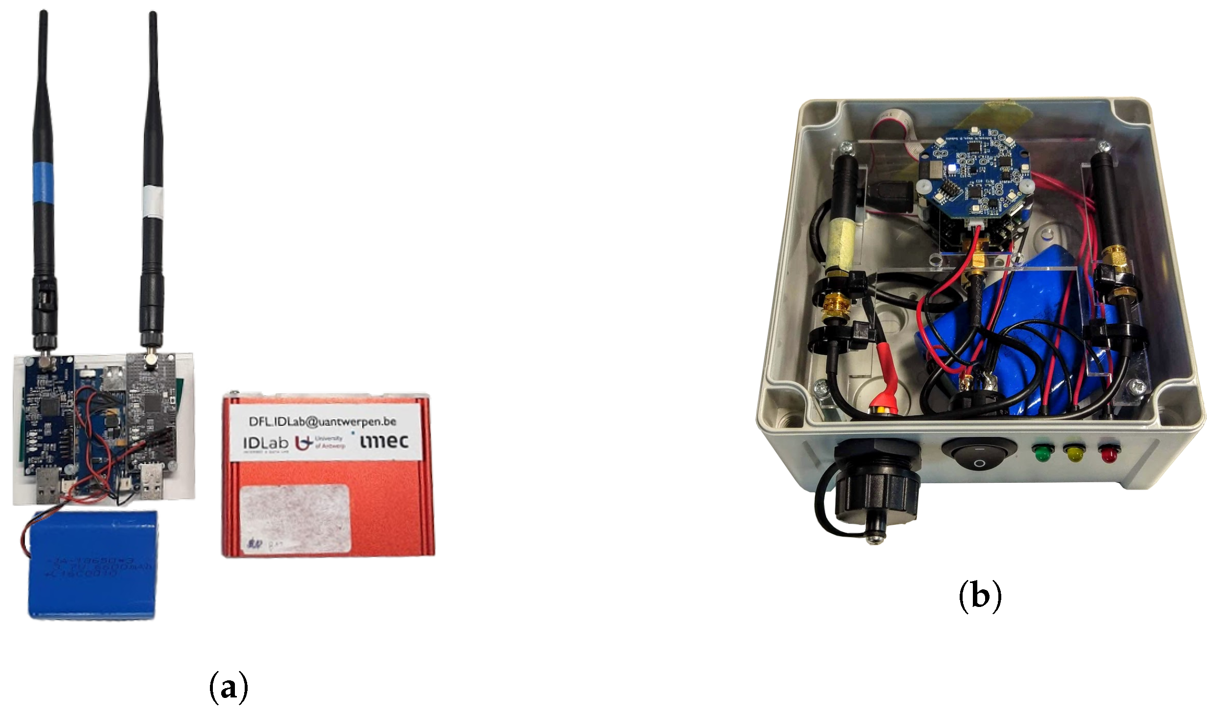
From the application perspective we make the distinction between three types of devices: the “nodes”, the controller and the configurator. First, what we call the ‘nodes’, which are the generic transceivers in the set-up, see Figure 2. They broadcast messages in a cyclic fashion, receiving while other nodes are transmitting; Second, the controller, which is a transceiver that coordinates the cycles when the nodes can send messages and at the same time receives and stores the node’s messages for further processing. Finally, the configurator, which is a transceiver that sends configuration data to a node upon request.
All nodes, controllers and configurators include a dedicated printed circuit board (PCB) for the 433 M Hz and 868 M Hz networks. Most nodes have both networks; only in the Main Comfort environment we use a few nodes with only the 868 M Hz network. Each PCB is equipped with an ARM Cortex-M3 microcontroller from the EZR32LG family and a Si4460 sub-GHz transceiver. The complete unit is powered by a 6600 mAh LiPo battery and protected from the elements by an encapsulation.
Figure 2a shows the first encapsulation and PCB iteration of the nodes. The antennas are fitted on the outside and the encapsulation itself is not water resistant. We use this first type in the Freedom Stage environment, because it is a sheltered environment. Figure 2b shows the second iteration of the nodes. The antennas are fitted on the inside and the encapsulation is waterproof. We use this second type in the Main Comfort environment, because part of that environment is open air.
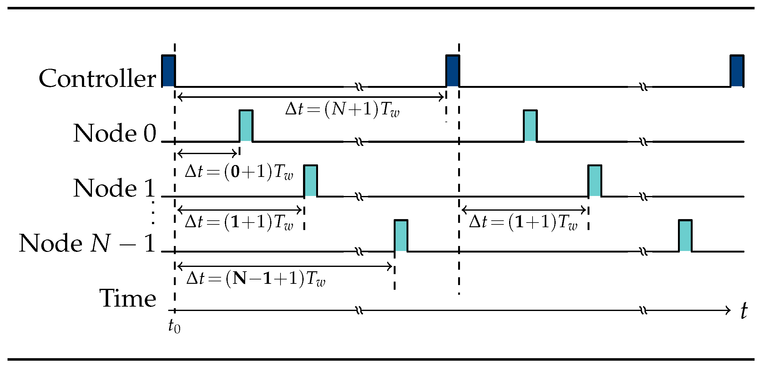
The controller periodically broadcasts a message to indicate that a cycle starts. Upon receiving this message, the nodes schedule their transmission one after the other. In turn, every node broadcasts a message to the controller and the other nodes. While the payload is only meant for the controller, other nodes use this message to measure and store the RSSI. Each node stores the RSSI values in a vector at the index of the transmitting node’s ID. This RSSI vector is the payload that the node sends to the controller. Figure 1 illustrates the formation of a single node’s RSSI vector. Note that the vector appears to hold positive integers, but in reality, they are negative values expressed in dBm .
Iterating through cycles in an orderly manner is enabled by a preconfigured wait time T w . According to T w , nodes schedule their transmission within the current cycle and the controller schedules the next cycle. In our set-up, T w = 50 ticks, with one tick equal to 2 −10 s or approximately 0.977 m s . Figure 3 visualises the communication cycles. As soon as the controller signals the start of a new cycle at t 0 , a network node with ID n schedules its transmission at t 0 + ( n + 1 ) T w . The network nodes do not schedule a second transmission, but rather await the next start signal at t 0 + ( N + 1 ) T w by the controller.
The configurator is responsible for setting the network specific parameters and the nodes’ IDs, based on their hardware ID. The parameters are network size N and wait time T w . As explained above, T w is used in combination with the node ID to define how long a node has to wait before it can send its measurements. Table 3 displays the communication channel parameters.
Figure 4 displays the node positions of the three environments. The nodes are indicated by their node ID. Some node IDs, such as 29 and 32 in Figure 4b, are skipped because they were not deployed. The placement of the devices is such that the direct line of sight paths between nodes cover as much of the environment as possible. Although the heights at which the nodes were placed are not provided in the datasets, we aimed to place the nodes at approximately 1 m from the ground.

3.2. Reference Data

For the Freedom Stage environments of both 2017 and 2018 we do not have crowd count references. As an alternative, which has an indirect correlation with the crowd count, we have the real-time data on cashless payment transactions per minute at the two bars of the environment.
In order to be admitted to the Main Comfort area, attendees are required to scan their bracelets. Bracelets are also scanned upon exit, which makes it so that crowd counts can be tracked over time. This is the available crowd count reference data for this environment.
However, there are two caveats: Attendees who pass through the Main Comfort to reach the more exclusive upper floors (B2B and Skyboxes) are also contributing to the scan-based crowd counts, without affecting our measurement set-up. We did not have nodes deployed in the B2B and Skyboxes in 2018, so we cannot account for the ratio of crowd size between the ground floor (Main Comfort) and the upper two floors. Another side note is that only attendees are scanned, meaning that the staff on the premises affect our measurements, but are not accounted for in the scan system.

4. Usage Notes

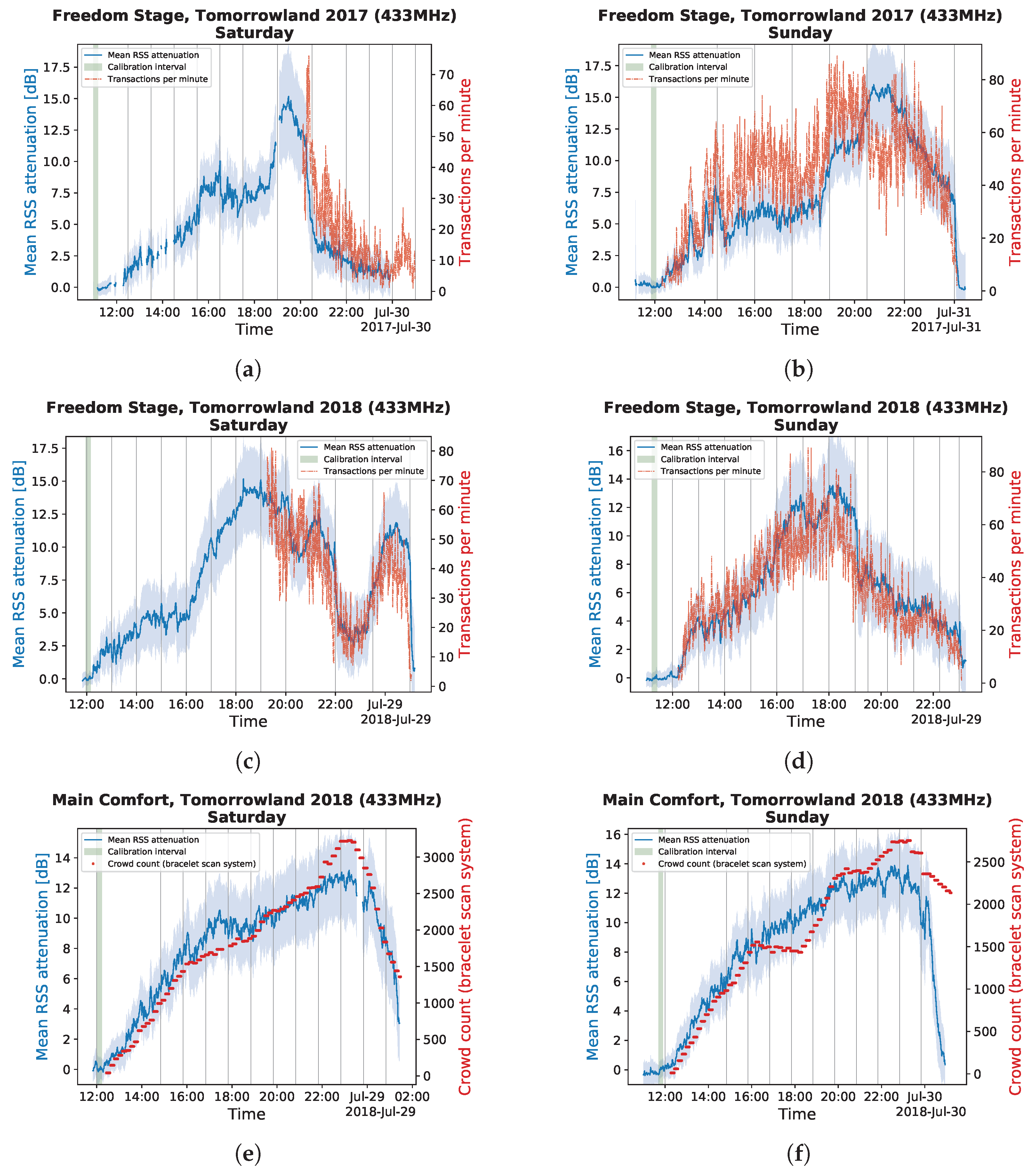
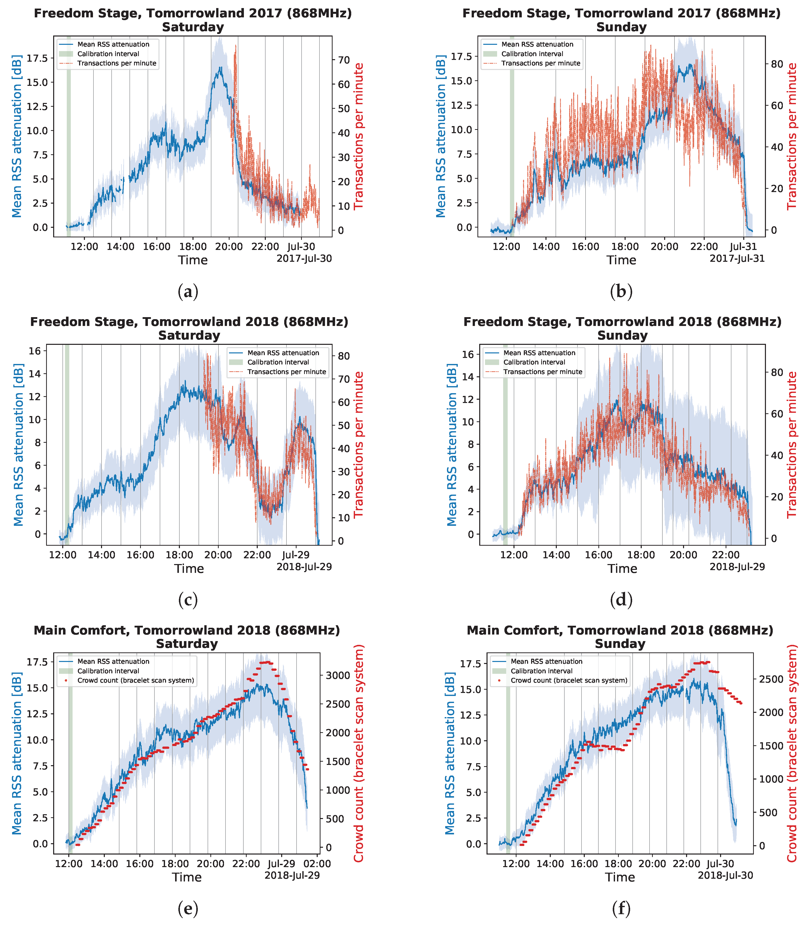
Along with the data files, we provide a script that loads a dataset, executes an example calibration and creates RSS attenuation graphs, overlaid with the corresponding reference data. Figure 5 and Figure 6 shows the resulting graphs. This RSS attenuation is the foundation for the crowd density estimation in [11].
The purpose of recording a calibration is to have a stable state of the communication links to which we can compare future RSS across links. The magnitude of RSS attenuation across the collection of communication links is then indicative of the surplus of people affecting these links. The surplus of people is ideally estimated with respect to a stable empty environment. There are two things we need for a good calibration: having a reference of the number of people in the environment and a sufficiently long time frame in which the count changes as little as possible.
We know that in the first hour of the measurements, there are a minimal amount of people in the environments. The reason for this is that during this time the artists’ sets have not yet started. The mean RSS across links are at their highest, because there are not many people to attenuate the signals. We narrow this one hour down to a calibration duration of ten minutes, while trying to select the range in which both the average RSS and standard deviation are as low as possible. Resulting calibration ranges are indicated by a green vertical band, with a width of ten minutes.
We can now use the RSSI vectors within the calibration interval to create a calibration vector of length N (number of nodes) for each node. For any given node, the vector contains the average RSS values for each link between itself and the other N 1 nodes, with a 0 entry for its own node ID index within that vector. These calibration vectors are now representative of an empty environment. The calibration vectors are then subtracted from subsequent time-averaged RSSI vectors. Moreover, if we time-average those subsequent RSSI vectors, we get the mean RSS attenuations, which are plotted in Figure 5 for the 433 M Hz networks and Figure 6 for the 868 M Hz networks. The lighter bands below and above the mean RSS attenuation are the additions of the rolling standard deviation of the mean RSS attenuation in the past calibration duration.
The Freedom Stage environment graphs shown in Figure 5a–d and Figure 6a–d are overlaid with the cashless payment transactions per minute. The Main Comfort environment has the bracelet count system data overlaid in Figure 5e,f and Figure 6e,f. The grey vertical lines indicate the beginnings and endings of artist sets, according to the planning.
The data interpretation and calibration described in this section is implemented in the shared script and serves as an example to use the provided data. By changing the unique year, environment, band and day parameters, the eighteen datasets can be used to generate graphs like the ones in Figure 5 and Figure 6.
Interestingly, the cashless transactions per minute in Figure 5a–d and Figure 6a–d follow the same global trend as the mean RSS attenuations (or relative crowd size), but the ratio of transactions per minute to mean RSS attenuations is consistently higher during an increasing crowd size, while being lower during decreasing RSS attenuations. Although a direct translation between crowd size and cashless payment rates is of little use, the reference data can still be used as a parameter in forecasting crowd sizes.
In Figure 5e,f and Figure 6e,f, we see two significant discrepancies between our mean RSS attenuations and the reported access control counts. Both on Saturday and Sunday, starting at 5 p.m., we see that the reported reference crowd counts are lower than our mean RSS attenuations. This first inconsistency is likely due to the serving of appetisers at the Main Comfort, resulting in attendees from the upper floors to visit the ground floor. The last most notable difference is at the end of the festival on Sunday. As attendees left the environment, access control gates were no longer used, resulting in a significantly higher crowd count reported than what is more truthfully indicated by our mean RSS attenuations. Our impressions and findings were communicated to and confirmed by the event organisers.

Author Contributions

Conceptualisation, methodology, software, investigation, data curation, S.D., B.B. and A.K.; resources, validation and visualisation, A.K. and S.D.; writing—original draft preparation, A.K. and R.B.; writing—review and editing, S.D., B.B. and M.W.; supervision, M.W. and R.B. All authors have read and agreed to the published version of the manuscript.

Funding

Abdil Kaya is funded by “Fonds Wetenschappelijk Onderzoek—Vlaanderen” under grant number “1S99720N”.

Acknowledgments

We thank the Tomorrowland organisers for allowing and enabling the measurement campaigns during their festival. It has been imperative to making this publication and our research possible.

Conflicts of Interest

The authors declare no conflicts of interest.

References

  1. Denis, S.; Berkvens, R.; Weyn, M. A survey on detection, tracking and identification in radio frequency-based device-free localization. Sensors (Switzerland) 2019, 19, 5329. [Google Scholar] [CrossRef] [PubMed] [Green Version]
  2. Zanella, A. Best practice in RSS measurements and ranging. IEEE Commun. Surv. Tutor. 2016, 18, 2662–2686. [Google Scholar] [CrossRef]
  3. Torres-Sospedra, J.; Moreira, A.; Knauth, S.; Berkvens, R.; Montoliu, R.; Belmonte, O.; Trilles, S.; João Nicolau, M.; Meneses, F.; Costa, A. A realistic evaluation of indoor positioning systems based on Wi-Fi fingerprinting: The 2015 EvAAL–ETRI competition. J. Ambient. Intell. Smart Environ. 2017, 9, 263–279. [Google Scholar] [CrossRef] [Green Version]
  4. Kamińska-Chuchmała, A.; Graña, M. Indoor Crowd 3D Localization in Big Buildings from Wi-Fi Access Anonymous Data. Sensors 2019, 19, 4211. [Google Scholar] [CrossRef] [PubMed] [Green Version]
  5. Yuan, Y.; Qiu, C.; Xi, W.; Zhao, J. Crowd density estimation using wireless sensor networks. In Proceedings of the 2011 7th International Conference on Mobile Ad-hoc and Sensor Networks, MSN 2011, Beijing, China, 16–18 December 2011; pp. 138–145. [Google Scholar] [CrossRef]
  6. Halperin, D.; Hu, W.; Sheth, A.; Wetherall, D. Tool release: Gathering 802.11n traces with channel state information. Comput. Commun. Rev. 2011, 41, 53. [Google Scholar] [CrossRef]
  7. Sobron, I.; Del Ser, J.; Eizmendi, I.; Velez, M. Device-Free People Counting in IoT Environments: New Insights, Results, and Open Challenges. IEEE Internet Things J. 2018, 5, 4396–4408. [Google Scholar] [CrossRef]
  8. Xi, W.; Zhao, J.; Li, X.Y.; Zhao, K.; Tang, S.; Liu, X.; Jiang, Z. Electronic frog eye: Counting crowd using WiFi. In Proceedings of the EEE INFOCOM 2014—IEEE Conference on Computer Communications, Toronto, ON, Canada, 27 April–2 May 2014; pp. 361–369. [Google Scholar] [CrossRef] [Green Version]
  9. P802.11ah/D5.0, Mar 2015 - IEEE Standard for Information Technology—Telecommunications and Information Exchange between Systems—Local and Metropolitan Area Networks—Specific Requirements—Part 11 Wireless LAN Medium Access Control (MAC) and Physical; IEEE: Piscataway, NJ, USA, 2015.
  10. Denis, S.; Berkvens, R.; Bellekens, B.; Weyn, M. Large Scale Crowd Density Estimation Using a sub-GHz Wireless Sensor Network. In Proceedings of the 2018 IEEE 29th Annual International Symposium on Personal, Indoor and Mobile Radio Communications (PIMRC), Bologna, Italy, 9–12 September 2018; pp. 849–855. [Google Scholar] [CrossRef]
  11. Denis, S.; Bellekens, B.; Kaya, A.; Berkvens, R.; Weyn, M. Large-scale Crowd Analysis Through the Use of Passive Radio Sensing Networks. Sensors 2020, 20, 2624. [Google Scholar] [CrossRef] [PubMed]
  12. Kaya, A.; Denis, S.; Bellekens, B.; Weyn, M.; Berkvens, R. Large-Scale Dataset for Radio Frequency based Device-Free Crowd Estimation (Zenodo), May 2020. [CrossRef]
  13. DASH7 Alliance. DASH7 Alliance Protocol Specification v1.2. Available online: https://dash7-alliance.org/download-specification/ (accessed on 9 June 2020).
  14. Weyn, M.; Ergeerts, G.; Berkvens, R.; Wojciechowski, B.; Tabakov, Y. DASH7 alliance protocol 1.0: Low-power, mid-range sensor and actuator communication. In Proceedings of the 2015 IEEE Conference on Standards for Communications and Networking, Tokyo, Japan, 28–30 October 2016; pp. 54–59. [Google Scholar] [CrossRef]
Figure 1. Each line in the dataset files corresponds to a message received by the Controller, such as the one sent by Node 33 in the example above. There are N nodes and a controller in the network. A zero entry in the rssi_values vector means that the listening node (Node 33 in the example) did not receive a message from the node ID with the corresponding vector index in the past cycle.
Data 05 00052 g001
Figure 2. We designed and deployed two types of nodes throughout the years: (a) The first iteration in a sturdy but open encapsulation, always featuring both the 433 MHz and 868 MHz networks. (b) The second iteration with a waterproof encapsulation, featuring either both networks or just the 868 MHz network. Both types are powered by a 6600 mAh battery and have an independently working microcontroller for each network.
Data 05 00052 g002
Figure 3. Communication cycle example with N nodes and a controller in the network. Controllers send a message that starts the cycle, after which the controller itself waits for T w ( N + 1 ) before broadcasting another start cycle message. Network devices schedule the transmission of their vector with RSSI values at an interval of T w . After transmitting their payload, the vector is reset to zeroes, to be populated by the time the node can transmit again. The duration of transmissions as depicted in this figure depends on the payload size and the communication protocol.
Data 05 00052 g003
Figure 4. Network node and controller positions at (a) Freedom Stage 2017, (b) Freedom Stage 2018 and (c) Main Comfort 2018 environments. The 433 M Hz and 868 M Hz nodes share the same position, although there are fourteen positions in the Main Comfort environment that only have a 868 M Hz node. These positions are indicated with a triangle and these nodes have IDs of 40 and above.
Data 05 00052 g004
Figure 5. 433 MHz RSS attenuation graphs as generated by our example script. (a) Saturday and (b) Sunday of the Freedom Stage 2017 environment, and (c) Saturday and (d) Sunday of the Freedom Stage 2018 environment are overlaid with the cashless transactions per minute. (e) Saturday and (f) Sunday of the Main Comfort 2018 environment are overlaid with the scan system-based crowd counts. Green vertical bands indicate the interval of data used for the calibration. Grey vertical lines indicate the beginning and end of a DJ set at the festival. The rolling standard deviation of the mean RSS attenuation is indicated as a light blue band around the mean RSS attenuation graph (±1σ).
Data 05 00052 g005
Figure 6. 868 MHz RSS attenuation graphs as generated by our example script. (a) Saturday and (b) Sunday of the Freedom Stage 2017 environment, and (c) Saturday and (d) Sunday of the Freedom Stage 2018 environment are overlaid with the cashless transactions per minute. (e) Saturday and (f) Sunday of the Main Comfort 2018 environment are overlaid with the scan system based crowd counts. Green vertical bands indicate the interval of data used for the calibration. Grey vertical lines indicate the beginning and end of a DJ set at the festival. The rolling standard deviation of the mean RSS attenuation is indicated as a light blue band around the mean RSS attenuation graph (±1σ).
Data 05 00052 g006
Table 1. To help investigate crowd sensing, we shared these eighteen dataset files. Where possible, we added a reference file with either transactions per minute at the bars in the environment, or people count in the exclusive zone as estimated by the access control system. We also provide position files for the nodes in each environment and line-up files for each day at each environment; we did not list them here.
Dataset FileReference File
free17_433_fri.csvNone
free17_868_fri.csvNone
free17_433_sat.csvfree17_transactions.csv
free17_868_sat.csvfree17_transactions.csv
free17_433_sun.csvfree17_transactions.csv
free17_868_sun.csvfree17_transactions.csv
free18_433_fri.csvNone
free18_868_fri.csvNone
free18_433_sat.csvfree18_transactions.csv
free18_868_sat.csvfree18_transactions.csv
free18_433_sun.csvfree18_transactions.csv
free18_868_sun.csvfree18_transactions.csv
main18_433_fri.csvNone
main18_868_fri.csvNone
main18_433_sat.csvmain18_counts.csv
main18_868_sat.csvmain18_counts.csv
main18_433_sun.csvmain18_counts.csv
main18_868_sun.csvmain18_counts.csv
Table 2. Brief overview of the 18 dataset files, made unique by the combinations of environment, year, frequency band, and day. The environment surface area provided in the table refers to the area of the polygon formed by the deployed nodes.
EnvironmentDayTime (24 h)Message CountsReferenceArea ( m 2 )
433 MHz868 MHz
Freedom Stage 2017Friday11:00–01:30393,852472,202Transactions1654.52
Nodes at 433 MHz: 46Saturday11:00–01:30996,0331,023,059
Nodes at 868 MHz: 46Sunday11:00–01:301007,0661,036,456
Freedom Stage 2018Friday11:00–01:30765,024757,657Transactions1686.06
Nodes at 433 MHz: 46Saturday11:50–01:30711,438714,390
Nodes at 868 MHz: 46Sunday11:00–01:30648,329656,290
Main Comfort 2018Friday11:00–01:30791,462908,407People count1252.30
Nodes at 433 MHz: 40Saturday11:00–01:30863,666884,682
Nodes at 868 MHz: 54Sunday11:00–01:30903,862894,496
Table 3. Most of the network parameters are the same for all nodes; only the duty cycle is different depending on the frequency band in the Main Comfort environment. The transmission power is the output power as configured in the devices.
ProtocolDASH7
Channel accessCSMA-CA
Data rate (normal-rate)55.55 kbps
Occupied bandwidth156 kHz
Modulation scheme2-GFSK
Modulation index1.8
Transmission Power16 dBm
Frequency band433 MHz868 MHz
Duty cycle per device
      Freedom 20170.37%0.37%
      Freedom 20180.37%0.37%
      Main Comfort 20180.38%0.36%