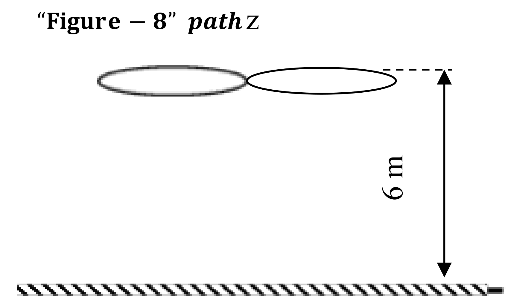
Autonomous “Figure-8” Flights of a Quadcopter: Experimental Datasets

Abstract
:1. Summary
- Facilitate performance evaluation of a widely used Commodity-Off-The-Shelf (COTS) flight controller, Pixhawk 1 [6], under different conditions (GPS coverage, flight velocities, waypoints etc.)
- This data can be used for comparing the performance of different flight controllers on multirotor drones and to design/simulate/evaluate flight control algorithms.
- This data could be used to evaluate the workload on COTS flight controllers, as well as in the design and implementation of resource-aware flight control algorithms.
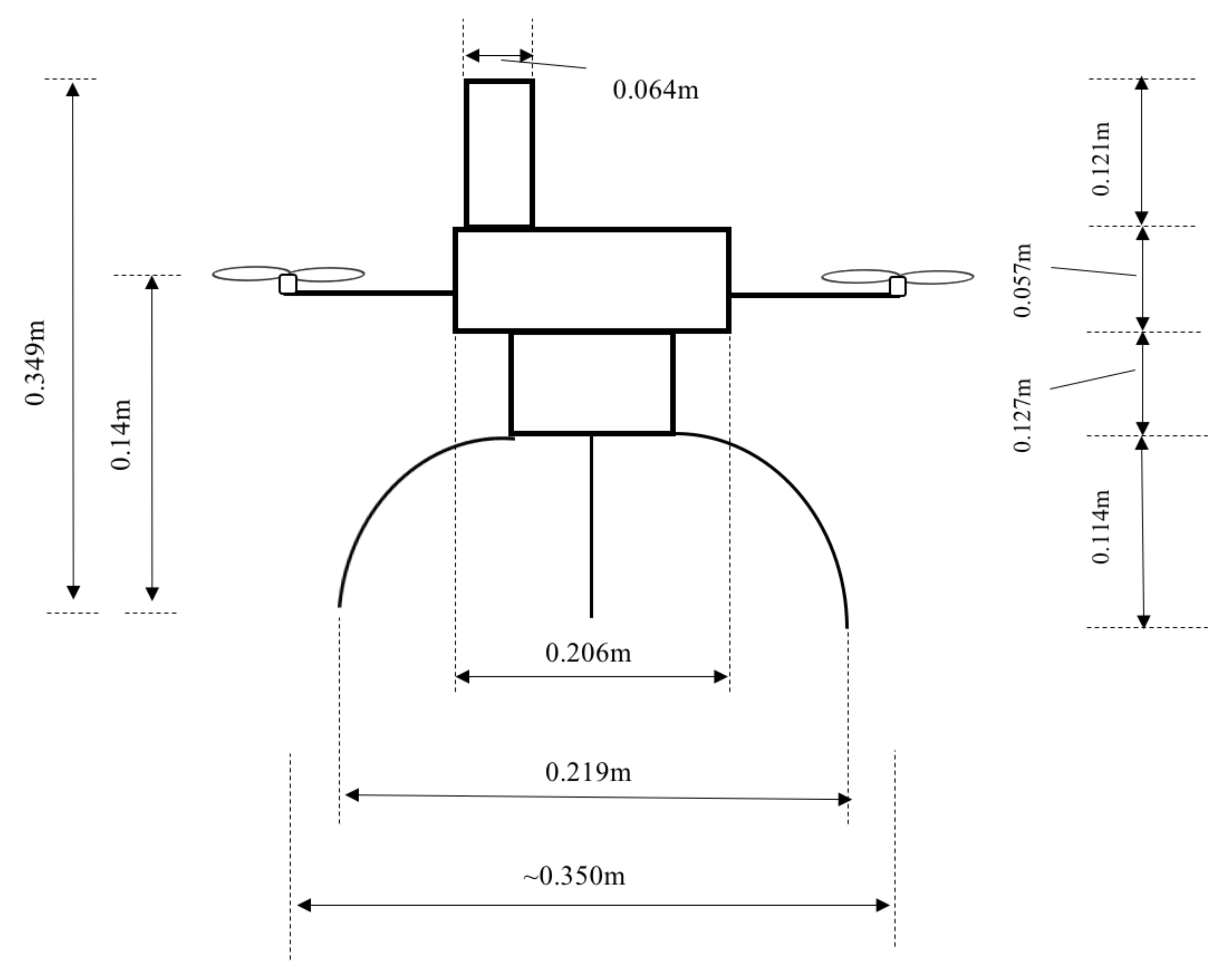
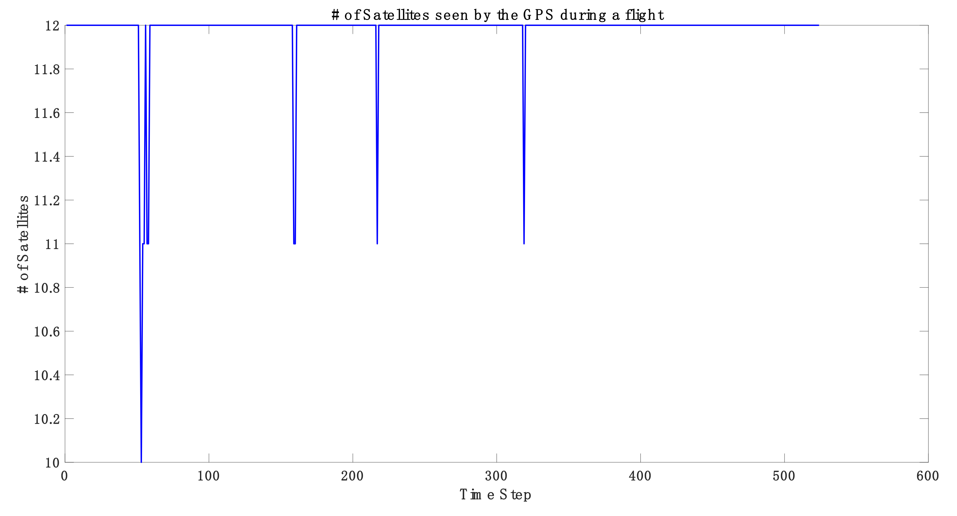
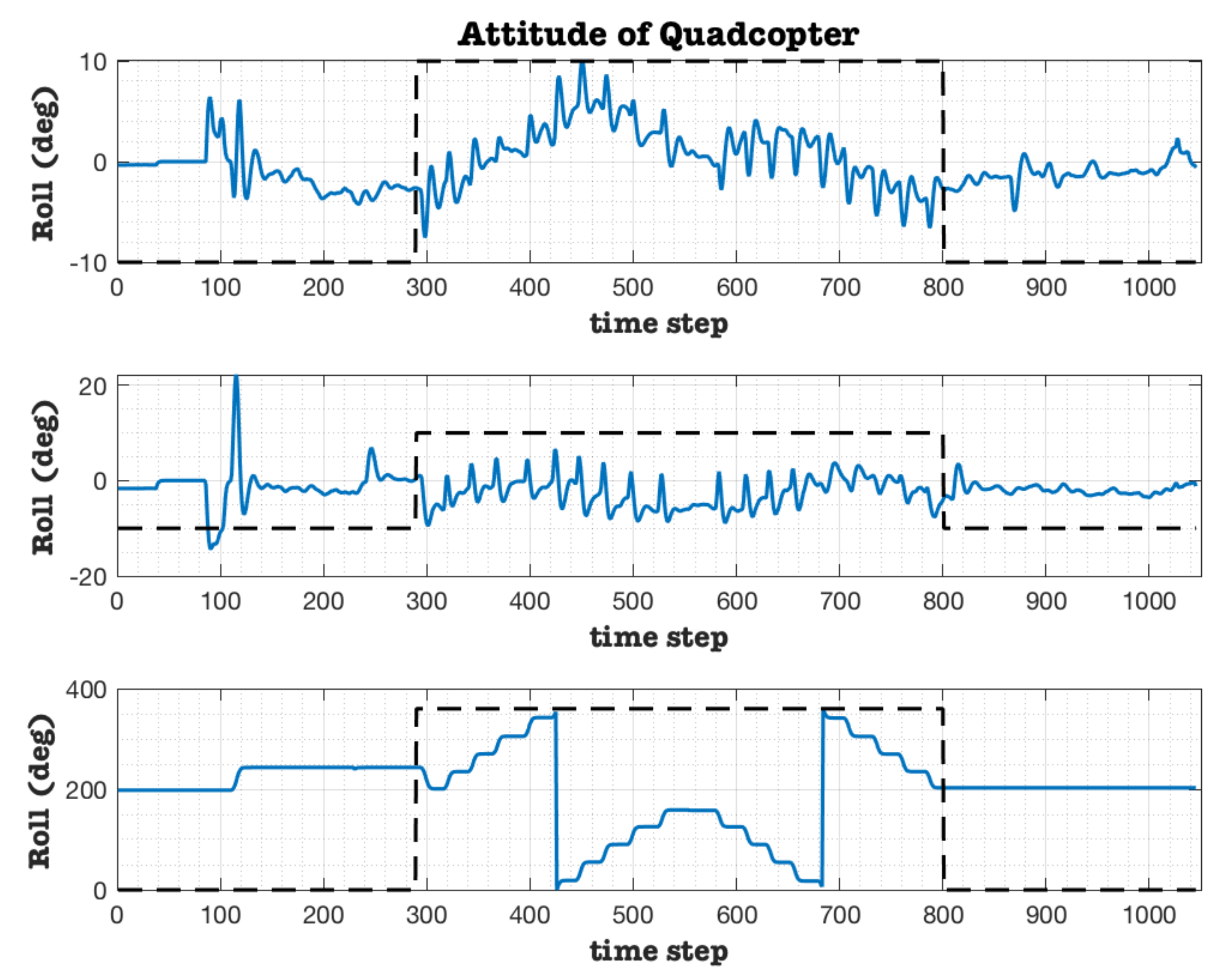
2. Data Description
3. Methods
4. User Notes
Supplementary Materials
Author Contributions
Funding
Acknowledgments
Conflicts of Interest
References
- FAA sUAS Part 107: The Small UAS Rule. Available online: https://www.faa.gov/uas/media/Part_107_Summary.pdf (accessed on 7 March 2019).
- Sun, Z.; Zhang, Y. Using Drones and 3D Modeling to Survey Tibetan Architectural Heritage: A Case Study with the Multi-Door Stupa. Sustainability 2018, 10, 7. [Google Scholar] [CrossRef]
- Molina, P.; Colomina, I.; Victoria, P.; Skaloud, J.; Kornus, W.; Prades, R.; Aguilera, C. Drones to the Rescue! Inside GNSS; July/August 2012. Available online: http://infoscience.epfl.ch/record/180464 (accessed on 7 March 2019).
- Câmara, D. Cavalry to the rescue: Drones fleet to help rescuers operations over disasters scenarios. In Proceedings of the 2014 IEEE Conference on Antenna Measurements & Applications (CAMA), Antibes Juan-les-Pins, France, 16–19 November 2014; pp. 1–4. [Google Scholar]
- Silvagni, M.; Tonoli, A.; Zenerino, E.; Chiaberge, M. Multipurpose UAV for search and rescue operations in mountain avalanche events. Geomat. Nat. Hazards Risk 2017, 8, 18–33. [Google Scholar] [CrossRef]
- Bai, Y. Control and Simulation of Morphing Quadcopter. Master’s Thesis, Parks College of Engineering, Aviation and Technology, Saint Louis University, St. Louis, MO, USA, December 2017. [Google Scholar]
- EKF2 Estimation System, Learning the ArduPilot Codebase. Available online: http://ardupilot.org/dev/docs/ekf2-estimation-system.html (accessed on 7 March 2019).
- Pixhawk 1 Flight Controller. Available online: https://docs.px4.io/en/flight_controller/pixhawk.html#specifications (accessed on 7 March 2019).
- AirCRAFT Laboratory. Aircraft Computational & Resource Aware Fault Tolerance (AirCRAFT) Lab; Parks College of Engineering, Aviation and Technology, Saint Louis University: St. Louis, MO, USA; Available online: https://sites.google.com/a/slu.edu/aircraft-lab/ (accessed on 7 March 2019).


| Variable | Descriptor (Variable Label) | Channels | Notes |
|---|---|---|---|
| AHR2 | AHR2_label | Roll, Pitch, Yaw, Alt, Lat, Lng | |
| ATT | ATT_label | DesRoll, Roll, DesPitch, Pitch, DesYaw, Yaw, ErrRP, ErrYaw, | |
| BARO | BARO_label | Alt, Press, Temp, CRt, SMS, Offset | |
| CMD | CMD_label | CTot, CNum, CId, Prm1, Prm2, Prm3, Prm4, Lat, Lng, Alt | This contains the waypoints that were commanded in the “Lat”, “Lng” and “Alt” channels |
| CTUN | CTUN_label | ThI, ABst, ThO, ThH, DAlt, Alt, BAlt, DSAlt, SAlt, TAlt, DCRt, CRt | Control, Throttle, and altitude information |
| CURR | CURR_label | Volt, Curr, CurrTot | |
| GPA | GPA_label | VDop, HAcc, VAcc, SAcc, VV, SMS | This contains the Vertical Dilution of Precision (VDOP) parameter |
| GPS | GPS_label | Status, GMS, GWk, NSats, HDop, Lat, Lng, Alt, Spd, GCrs, VZ, U | This contains the Horizontal Dilution of Precision (HDOP) parameter |
| IMU, IMU2 | IMU_label, IMU2_label | GyrX, GyrY, GyrZ, AccX, AccY, AccZ, ErrG, ErrA, Temp, GyHlt, AcHlt | Body axis angular rates () and accelerations () |
| MAG, MAG2 | MAG_label, MAG2_label | MagX, MagY, MagZ, OfsX, OfsY, OfsZ, MOfsX, MOfsY, MOfsZ, Health, S | |
| NKF1- NKF9 | NKF1_label–NKF9_label | Roll, Pitch, Yaw, VN, VE, VD, dPD, PN, PE, PD, GX, GY, GZ | More details can be found in [7] |
| PM | PM_label | NLon, NLoop, MaxT, PMT, I2CErr, INSErr, LogDrop | Performance Monitoring |
| POS | POS_label | Lat, Lng, Alt, RelAlt | Position Log |
| RCIN | RCIN_label | RC Inputs, Channels 1–16 | Channel 5 represents the switch to autonomous flight |
| RCOU | RCOU_label | Output of the flight controller | Channels 1–4 are the outputs of the flight controller, fed to the four speed controllers controlling the motors |
 3DR Pixhawk Flight Controller | Central Processign Unit (CPU) | 168 MHz Cortex-M4F |
| Input/Output | 14 PWM/Servo outputs | |
| Extra connectivity | UART, I2C, GPS | |
| Power distribution | Redundant power supplies | |
| Flight log | Pluggable microSD card | |
| Inertial Measurement Unit (IMU) | Invensense MPU6000 (ST Micro 3-axis 14 bit accelerometer, 3-axis, 16 bit gyro) | |
| GPS | 3DR GPS module |
| Motor | ESC | ||
 KDA 20-22 L Brushless Outrunner Motor. |  Plush 18 A ESC. | ||
| Kv | 924 | Burst Current | 22 A |
| Operating Current | 6–14 A | Constant Current | 18 A |
| Max. Voltage | 11 v | BEC | 5 v/2 A; Linear |
| Size/Weight | 28 × 32 mm; 56 g | LiPo | 2–4 cells |
| Size/Weight | 24 × 45 × 11 mm/19 g | ||
| Sensor | Original Sample Frequency | Resampled Frequency |
|---|---|---|
| ATT (Attitude) | 10 Hz | 25 Hz |
| CTUN (Altitude) | 10 Hz | 25 Hz |
| Curr (Current and Voltage) | 10 Hz | 25 Hz |
| IMU | 25 Hz | 25 Hz |
| IMU2 | 25 Hz | 25 Hz |
| NTUN (Velocity) | 10 Hz | 25 Hz |
| POS (Position, filtered from GPS) | 10 Hz | 25 Hz |
| RCOU (Controller output) | 10 Hz | 25 Hz |
| GPS | 5 Hz | 25 Hz |
© 2019 by the authors. Licensee MDPI, Basel, Switzerland. This article is an open access article distributed under the terms and conditions of the Creative Commons Attribution (CC BY) license (http://creativecommons.org/licenses/by/4.0/).
Share and Cite
Gururajan, S.; Bai, Y. Autonomous “Figure-8” Flights of a Quadcopter: Experimental Datasets. Data 2019, 4, 39. https://doi.org/10.3390/data4010039
Gururajan S, Bai Y. Autonomous “Figure-8” Flights of a Quadcopter: Experimental Datasets. Data. 2019; 4(1):39. https://doi.org/10.3390/data4010039
Chicago/Turabian StyleGururajan, Srikanth, and Ye Bai. 2019. "Autonomous “Figure-8” Flights of a Quadcopter: Experimental Datasets" Data 4, no. 1: 39. https://doi.org/10.3390/data4010039
APA StyleGururajan, S., & Bai, Y. (2019). Autonomous “Figure-8” Flights of a Quadcopter: Experimental Datasets. Data, 4(1), 39. https://doi.org/10.3390/data4010039