
Does Malpositioning of Pedicle Screws Affect Biomechanical Stability in a Novel Quasistatic Test Setup?

 , , ,
, , ,
Abstract
1. Introduction
2. Materials and Methods
2.1. Ethical Statement
2.2. Specimen and Tissue Preparation
2.3. Planning and Screw Positioning
2.4. Biomechanical Experiments
- Test not possible (no pedicle screw instrumented due to fracture, for example);
- Embedding error (e.g., embedded too deeply, screw in embedding compound);
- Error during instrumentation (e.g., drill guide slipped, screw position out of plane)
- Incorrect data recording;
- Side comparison not possible (because data evaluation of the comparison pedicle was excluded due to the above criteria).
2.5. Statistical Analysis
3. Results
Comparison of Malpositioning
4. Discussion
5. Limitations
6. Conclusions
Author Contributions
Funding
Institutional Review Board Statement
Data Availability Statement
Acknowledgments
Conflicts of Interest
Abbreviations
| vBMD | Bolumetric bone mineral content () |
| CT | Computer tomography |
| HU | Hounsfield unit |
References
- Burval, D.J.; McLain, R.F.; Milks, R.; Inceoglu, S. Primary pedicle screw augmentation in osteoporotic lumbar vertebrae: Biomechanical analysis of pedicle fixation strength. Spine 2007, 32, 1077–1083. [Google Scholar] [CrossRef]
- Cho, W.; Cho, S.K.; Wu, C. The biomechanics of pedicle screw-based instrumentation. J. Bone Jt. Surg. Br. 2010, 92, 1061–1065. [Google Scholar] [CrossRef]
- Nevzati, E.; Marbacher, S.; Soleman, J.; Perrig, W.N.; Diepers, M.; Khamis, A.; Fandino, J. Accuracy of pedicle screw placement in the thoracic and lumbosacral spine using a conventional intraoperative fluoroscopy-guided technique: A national neurosurgical education and training center analysis of 1236 consecutive screws. World Neurosurg. 2014, 82, 866–871.e1-2. [Google Scholar] [CrossRef] [PubMed]
- Tsagkaris, C.; Fasser, M.-R.; Farshad, M.; Passaplan, C.; Cornaz, F.; Widmer, J.; Spirig, J.M. Stability of medially and laterally malpositioned screws: A biomechanical study on cadavers. Spine J. 2025, 25, 380–388. [Google Scholar] [CrossRef] [PubMed]
- Gertzbein, S.D.; Robbins, S.E. Accuracy of pedicular screw placement in vivo. Spine 1990, 15, 11–14. [Google Scholar] [CrossRef]
- Floccari, L.V.; Larson, A.N.; Crawford, C.H.; Ledonio, C.G.; Polly, D.W.; Carreon, L.Y.; Blakemore, L. Which Malpositioned Pedicle Screws Should Be Revised? J. Pediatr. Orthop. 2018, 38, 110–115. [Google Scholar] [CrossRef]
- Maeda, T.; Higashino, K.; Manabe, H.; Yamashita, K.; Hayashi, F.; Goda, Y.; Tsuruo, Y.; Sairyo, K. Pullout Strength of Pedicle Screws Following Redirection After Lateral or Medial Wall Breach. Spine 2018, 43, E983–E989. [Google Scholar] [CrossRef]
- Ge, D.-W.; Chen, H.-T.; Qian, Z.-Y.; Zhang, S.; Zhuang, Y.; Yang, L.; Cao, X.-J.; Sui, T. Biomechanical strength impact of lateral wall breach on spinal pedicle screw fixation. Eur. Rev. Med. Pharmacol. Sci. 2018, 22, 63–68. [Google Scholar] [CrossRef]
- Goda, Y.; Higashino, K.; Toki, S.; Suzuki, D.; Kobayashi, T.; Matsuura, T.; Fujimiya, M.; Hutton, W.C.; Fukui, Y.; Sairyo, K. The Pullout Strength of Pedicle Screws Following Redirection After Lateral Wall Breach or End-plate Breach. Spine 2016, 41, 1218–1223. [Google Scholar] [CrossRef]
- Huang, X.; Huang, Z.; Xu, L.; Liang, D.; Zhang, M.; Zhang, H. Pullout strength of reinserted pedicle screws using the previous entry point and trajectory. J. Orthop. Surg. Res. 2019, 14, 205. [Google Scholar] [CrossRef]
- Kang, D.G.; Lehman, R.A.; Wagner, S.C.; Bevevino, A.J.; Bernstock, J.D.; Gaume, R.E.; Dmitriev, A.E. Pedicle screw reinsertion using previous pilot hole and trajectory does not reduce fixation strength. Spine 2014, 39, 1640–1647. [Google Scholar] [CrossRef]
- Kalemci, O.; Kizmazoglu, C.; Ozyoruk, S.; Uzunoglu, I.; Husemoglu, B.; Atar, M.; Aydin, H.E.; Karakasli, A. What is the Effect of Pedicle Screw Reinsertion Through the Same Trajectory on Pullout Strength? Turk. Neurosurg. 2022, 32, 635–640. [Google Scholar] [CrossRef] [PubMed]
- Jarvers, J.-S.; Schleifenbaum, S.; Pfeifle, C.; Oefner, C.; Edel, M.; von der Höh, N.; Heyde, C.-E. Comparison of three different screw trajectories in osteoporotic vertebrae: A biomechanical investigation. BMC Musculoskelet. Disord. 2021, 22, 418. [Google Scholar] [CrossRef]
- Metzner, F.; Reise, R.; Heyde, C.-E.; von der Höh, N.H.; Schleifenbaum, S. Side specific differences of Hounsfield-Units in the osteoporotic lumbar spine. J. Spine Surg. 2024, 10, 232–243. [Google Scholar] [CrossRef]
- Brett, A.D.; Brown, J.K. Quantitative computed tomography and opportunistic bone density screening by dual use of computed tomography scans. J. Orthop. Translat. 2015, 3, 178–184. [Google Scholar] [CrossRef]
- Schleifenbaum, S.; Vogl, A.-C.; Heilmann, R.; von der Hoeh, N.H.; Heyde, C.-E.; Jarvers, J.-S. Biomechanical comparative study of midline cortical vs. traditional pedicle screw trajectory in osteoporotic bone. BMC Musculoskelet. Disord. 2023, 24, 395. [Google Scholar] [CrossRef]
- ASTM F1717-15; Standard Test Method for Spinal Implant Constructs in a Vertebrectomy Model. ASTM: West Conshohocken, PA, USA, 2015.
- Reichle, E.; Morlock, M.; Sellenschloh, K.; Eggers, C. Zur Definition der Pedikelfehllage. Primärstabilität und Lockerungsverhalten von Pedikelschrauben in Abhängigkeit von ihrer Lage: Spongiöse Verankerung, kortikale Verankerung, Perforation und Fehllage. Orthopade 2002, 31, 402–405. [Google Scholar] [CrossRef]
- LeRoy, T.E.; Smith, I.C.; Kim, D.H.; Golenbock, S.W.; Baker, K.C.; Arnold, P.M.; Sasso, R.C.; Park, D.K.; Fischgrund, J.S.; Zaidi, Q.H.; et al. Clinical Significance of Lateral Pedicle Screw Malposition in Lumbar Spine Fusion. Clin. Spine Surg. 2023, 36, E258–E262. [Google Scholar] [CrossRef]
- Rohlmann, A.; Bergmann, G.; Graichen, F. Loads on internal spinal fixators measured in different body positions. Eur. Spine J. 1999, 8, 354–359. [Google Scholar] [CrossRef]
- Song, F.; Liu, Y.; Fu, R.; Gao, X.; Iqbal, K.; Yang, D.; Liu, Y.; Yang, H. Craniocaudal toggling increases the risk of screw loosening in osteoporotic vertebrae. Comput. Methods Programs Biomed. 2023, 238, 107625. [Google Scholar] [CrossRef]
- Aoude, A.; Ghadakzadeh, S.; Alhamzah, H.; Fortin, M.; Jarzem, P.; Ouellet, J.A.; Weber, M.H. Postoperative Assessment of Pedicle Screws and Management of Breaches: A Survey among Canadian Spine Surgeons and a New Scoring System. Asian Spine J. 2018, 12, 37–46. [Google Scholar] [CrossRef]
- Woo, E.J.; DiCuccio, M.N. Clinically significant pedicle screw malposition is an underestimated cause of radiculopathy. Spine J. 2018, 18, 1166–1171. [Google Scholar] [CrossRef]
- Ouyang, H.; Hu, Y.; Hu, W.; Zhang, H.; Sun, Z.; Tang, Y.; Jiang, Y.; Chen, J.; Dong, S.; Li, W.; et al. Incidences, causes and risk factors of unplanned reoperations within 30 days of spine surgery: A single-center study based on 35,246 patients. Spine J. 2022, 22, 1811–1819. [Google Scholar] [CrossRef]
- Demura, S.; Ohara, T.; Tauchi, R.; Takimura, K.; Watanabe, K.; Suzuki, S.; Uno, K.; Suzuki, T.; Yanagida, H.; Yamaguchi, T.; et al. Incidence and causes of instrument-related complications after primary definitive fusion for pediatric spine deformity. J. Neurosurg. Spine 2023, 38, 192–198. [Google Scholar] [CrossRef]
- Schmoelz, W.; Kienle, A. Mechanical and Biomechanical Testing of Spinal Implants. In Manual of Spine Surgery; Vieweg, U., Grochulla, F., Eds.; Springer: Berlin/Heidelberg, Germany, 2023; pp. 23–27. ISBN 978-3-662-64062-3. [Google Scholar]

| Donor | 1 | 2 | 3 | 4 | 5 | |||||
|---|---|---|---|---|---|---|---|---|---|---|
| Level | Left | Right | Left | Right | Left | Right | Left | Right | Left | Right |
| T8 | m | c | c | sl | s | c | c | c | l | c |
| T9 | l | c | m | c | c | sl | c | s | c | c |
| T10 | c | c | c | l | m | c | c | sl | s | c |
| T11 | c | s | c | c | c | l | c | m | sl | c |
| T12 | c | sl | s | c | c | c | c | l | c | m |
| L1 | c | m | c | sl | s | c | c | c | l | c |
| L2 | l | c | m | c | c | sl | c | s | c | c |
| L3 | c | c | l | c | c | m | sl | c | c | s |
| L4 | c | s | c | c | l | c | m | c | c | sl |
| L5 | sl | c | c | s | c | c | c | l | c | m |
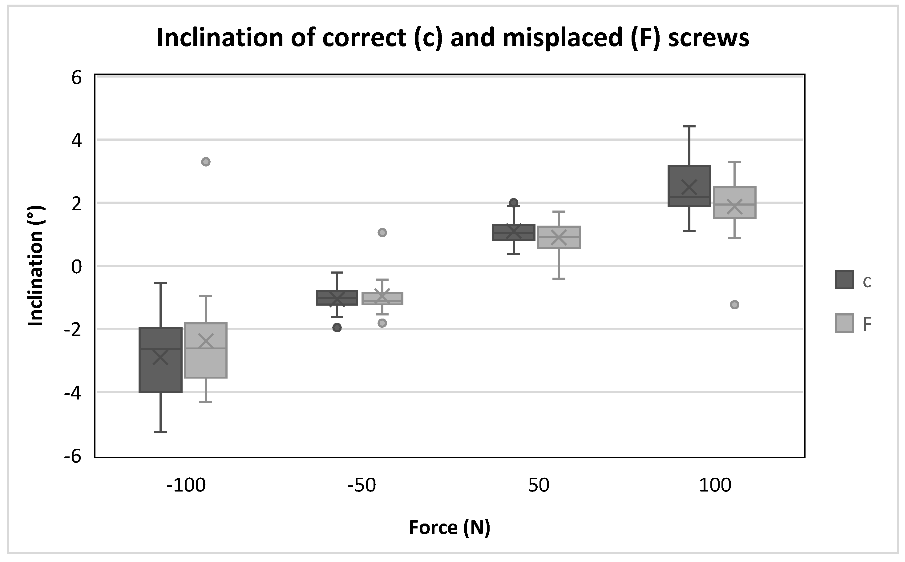
| Cycle | Force (N) | Correct Inclination (°) | Misplacement Inclination (°) | p-Value |
|---|---|---|---|---|
| 1 | −50 | −1.0 | −1.1 | 0.615 |
| 50 | 1.0 | 0.9 | 0.277 | |
| 2 | −100 | −2.7 | −2.6 | 0.355 |
| 100 | 2.2 | 1.9 | 0.026 |
Disclaimer/Publisher’s Note: The statements, opinions and data contained in all publications are solely those of the individual author(s) and contributor(s) and not of MDPI and/or the editor(s). MDPI and/or the editor(s) disclaim responsibility for any injury to people or property resulting from any ideas, methods, instructions or products referred to in the content. |
© 2025 by the authors. Licensee MDPI, Basel, Switzerland. This article is an open access article distributed under the terms and conditions of the Creative Commons Attribution (CC BY) license (https://creativecommons.org/licenses/by/4.0/).
Share and Cite
Schleifenbaum, S.; Metzner, F.; Schultze, J.; Kurz, S.; Heyde, C.-E.; Pieroh, P. Does Malpositioning of Pedicle Screws Affect Biomechanical Stability in a Novel Quasistatic Test Setup? Bioengineering 2025, 12, 781. https://doi.org/10.3390/bioengineering12070781
Schleifenbaum S, Metzner F, Schultze J, Kurz S, Heyde C-E, Pieroh P. Does Malpositioning of Pedicle Screws Affect Biomechanical Stability in a Novel Quasistatic Test Setup? Bioengineering. 2025; 12(7):781. https://doi.org/10.3390/bioengineering12070781
Chicago/Turabian StyleSchleifenbaum, Stefan, Florian Metzner, Janine Schultze, Sascha Kurz, Christoph-Eckhard Heyde, and Philipp Pieroh. 2025. "Does Malpositioning of Pedicle Screws Affect Biomechanical Stability in a Novel Quasistatic Test Setup?" Bioengineering 12, no. 7: 781. https://doi.org/10.3390/bioengineering12070781
APA StyleSchleifenbaum, S., Metzner, F., Schultze, J., Kurz, S., Heyde, C.-E., & Pieroh, P. (2025). Does Malpositioning of Pedicle Screws Affect Biomechanical Stability in a Novel Quasistatic Test Setup? Bioengineering, 12(7), 781. https://doi.org/10.3390/bioengineering12070781