
Digitalized Thermal Inspection Method of the Low-Frequency Stimulation Pads for Preventing Low-Temperature Burn in Sensitive Skin


Abstract
1. Introduction
2. Materials and Methods
2.1. Background Subtraction
2.2. Deviation of Pixel History
2.3. Morphological Filtering
2.4. Thermophysical Conditions
2.5. Experiment
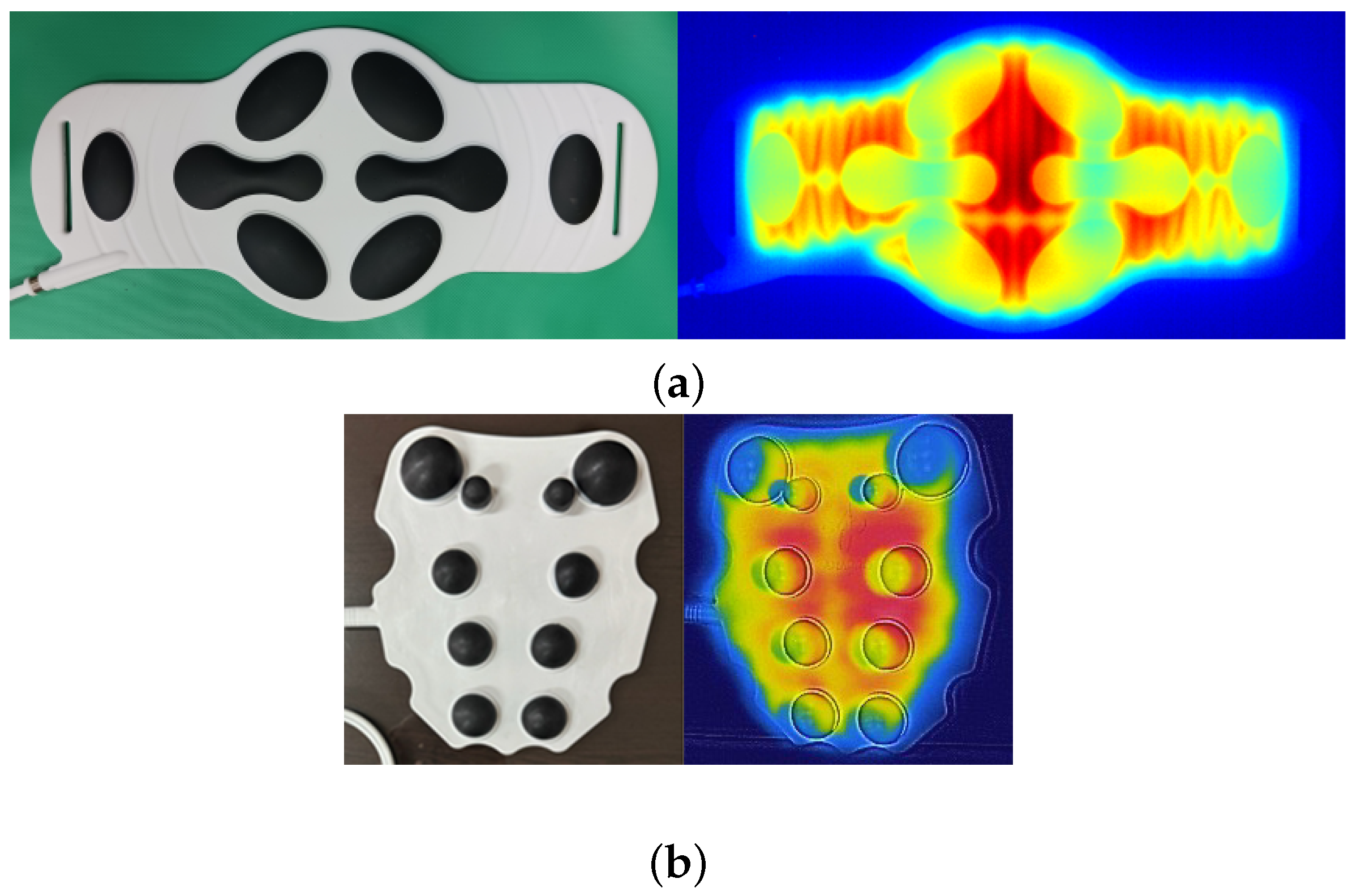
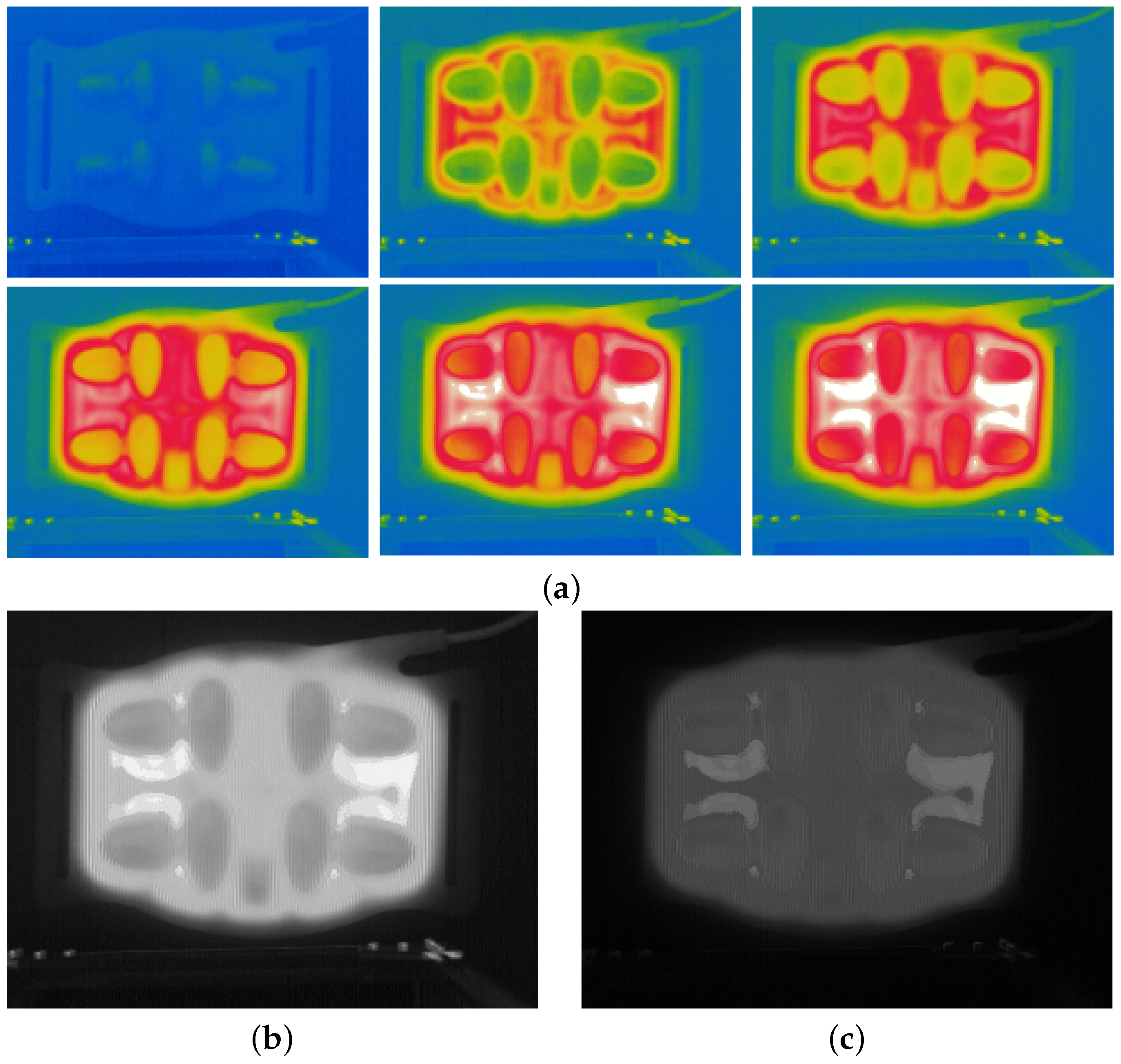
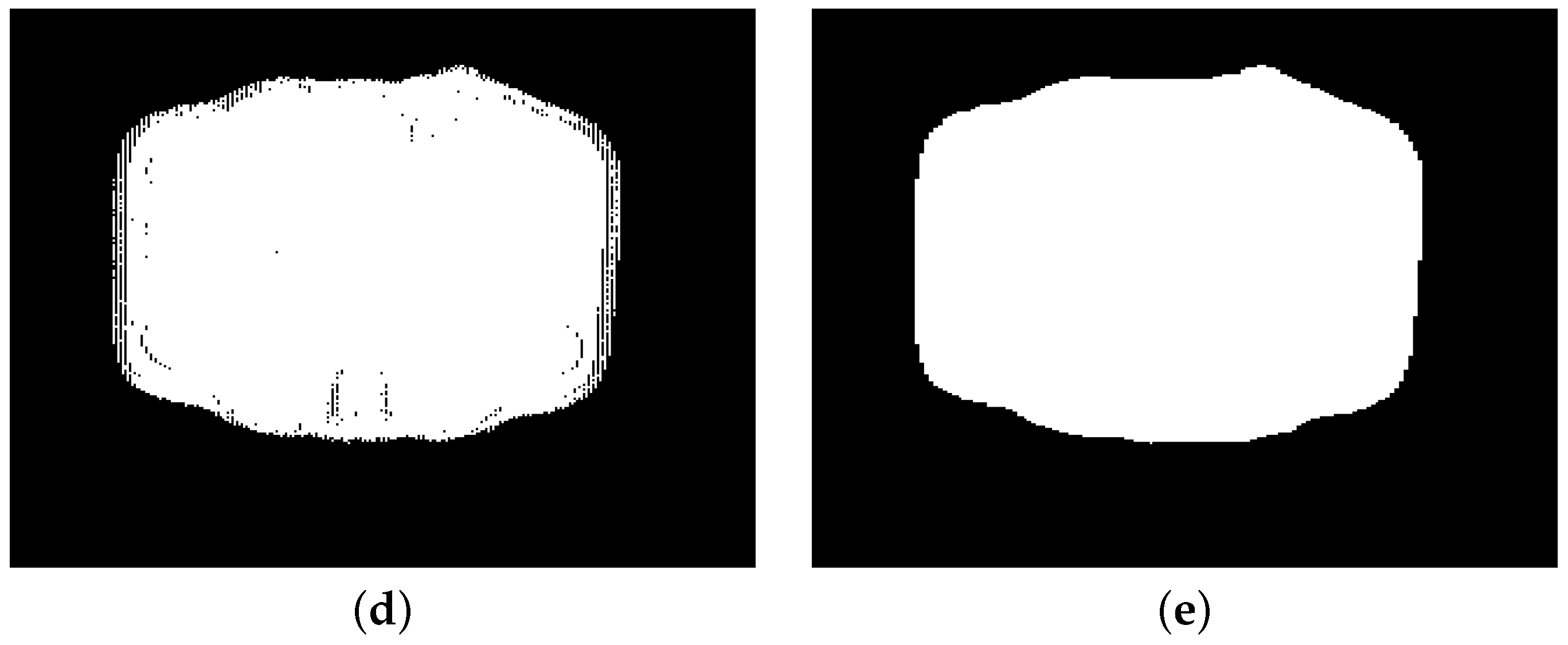
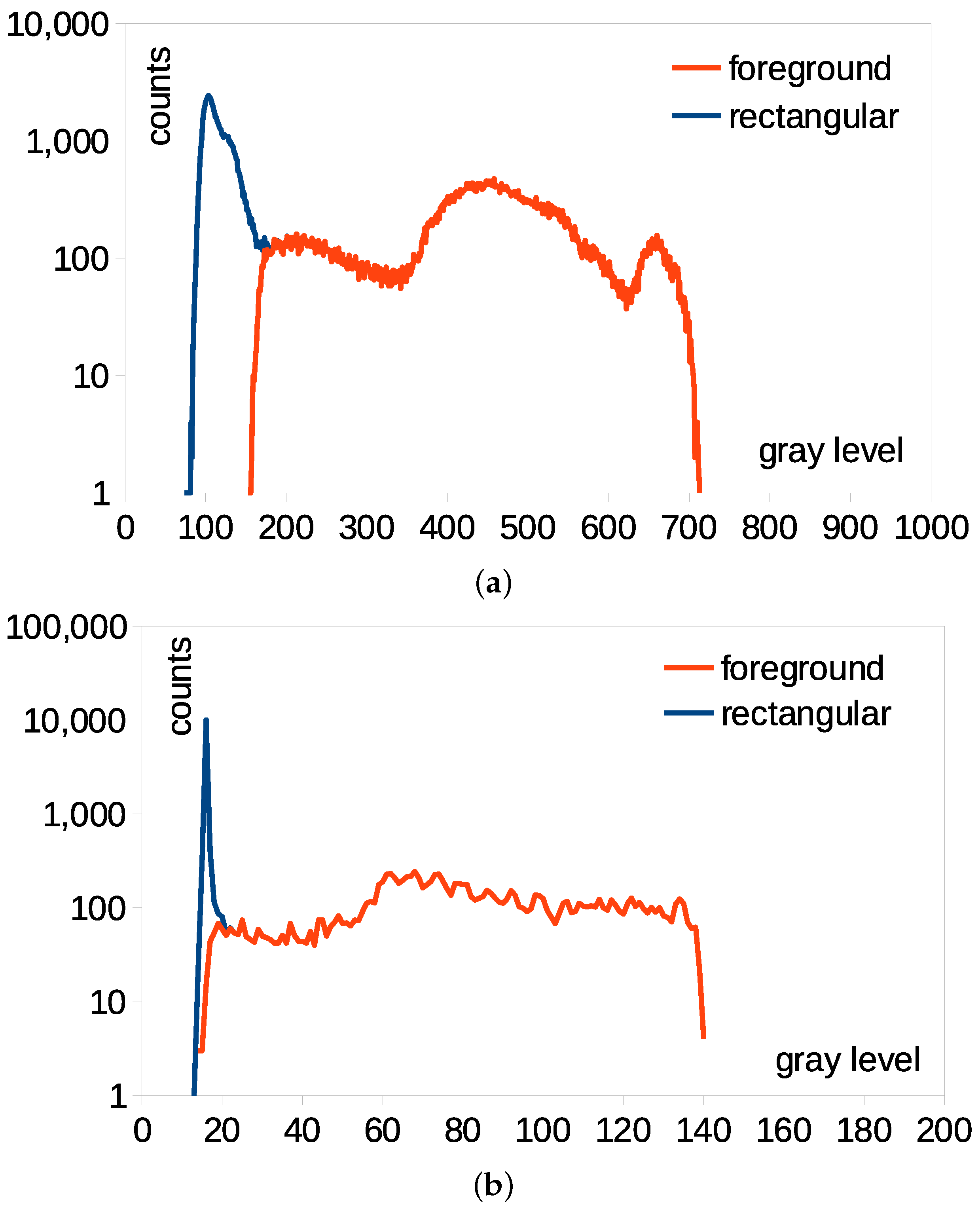
3. Results
4. Discussion
5. Conclusions
Author Contributions
Funding
Institutional Review Board Statement
Informed Consent Statement
Data Availability Statement
Conflicts of Interest
Abbreviations
| CNT | Count-based |
| FOV | Field of view |
| GMG | Godbehere–Matsukawa–Goldberg |
| GSOC | Google Summer of Code 2017 |
| KNN | K–nearest neighbor |
| LFS | Low frequency stimulation |
| LSBP | Local SVD binary pattern |
| LTB | Low-temperature burn |
| LWIR | Long-wave infrared ray |
| MOG | Mixture of Gaussian |
| ROI | Region of interest |
| SDPH | Standard deviation of a pixel history |
References
- Yoon, Y.S.; Ko, M.H.; Cho, I.Y.; Kim, C.S.; Bajgai, J.; Jang, H.Y.; Kim, K.E.; Lee, K.J.; Lee, M. Effects of Personal Low-Frequency Stimulation Device on Myalgia: A Randomized Controlled Trial. Int. J. Environ. Res. Public. Health 2022, 19, 735. [Google Scholar] [CrossRef]
- Sentandreu-Mañó, T.; Tomás, J.M.; Ricardo Salom Terrádez, J. A randomised clinical trial comparing 35 Hz versus 50 Hz frequency stimulation effects on hand motor recovery in older adults after stroke. Sci. Rep. 2021, 11, 9131. [Google Scholar] [CrossRef]
- Tamaki, H.; Yotani, K.; Ogita, F.; Hayao, K.; Kirimto, H.; Onishi, H.; Kasuga, N.; Yamamoto, N. Low-Frequency Electrical Stimulation of Denervated Skeletal Muscle Retards Muscle and Trabecular Bone Loss in Aged Rats. Int. J. Med. Sci. 2019, 16, 822–830. [Google Scholar] [CrossRef]
- Mettler, J.A.; Magee, D.M.; Doucet, B.M. Low-frequency electrical stimulation with variable intensity preserves torque. J. Electromyogr. Kinesiol. 2018, 42, 49–56. [Google Scholar] [CrossRef]
- Shenkman, B.S.; Lyubaeva, E.V.; Popov, D.V.; Netreba, A.I.; Bravy, Y.R.; Tarakin, P.P.; Lemesheva, Y.S.; Vinogradova, O.L. Chronic effects of low-frequency low-intensity electrical stimulation of stretched human muscle. Acta Astro. 2007, 60, 505–511. [Google Scholar] [CrossRef]
- Gremeaux, V.; Renault, J.; Pardon, L.; Deley, G.; Lepers, R.; Casilas, J.M. Low-Frequency Electric Muscle Stimulation Combined With Physical Therapy After Total Hip Arthroplasty for Hip-Osteoarthritis in Elderly Patients:A Randomized Controlled Trial. Arch. Phys. Med. Rehab. 2008, 89, 2265–2273. [Google Scholar] [CrossRef]
- Lee, M.; Zulbaran-Rojas, A.; Bargas-Ochoa, M.; Martinez-Leal, B.; Bara, R.; Flores-Camargo, A.; Finco, M.G.; Mishra, R.; Beom, J.; Modi, D.; et al. Gastrocnemius electrical stimulation increases ankle dorsiflexion strength in patients with post-acute sequelae of SARS-COV-2 (PASC): A double-blind randomized controlled trial. Sci. Rep. 2024, 14, 17939. [Google Scholar] [CrossRef]
- Narvani, A.; Thomas, P.; Lynn, B. Key Clinical Topics in Sports and Exercise Medicine; JP Medical: London, UK, 2014; pp. 226–227. [Google Scholar]
- Choi, M.S.; Lee, H.J.; Lee, J.H. Early Intervention for Low-Temperature Burns: Comparison between Early and Late Hospital Visit Patients. Arch. Plast. Surg. 2015, 42, 173–178. [Google Scholar] [CrossRef]
- Martin, N.A.; Falder, S. A review of the evidence for threshold of burn injury. Burns 2017, 43, 1624–1639. [Google Scholar] [CrossRef] [PubMed]
- Maayah, M.F.; Nawasreh, Z.H.; Gaowgzeh, R.; Neamatallah, Z.; Alfawaz, S.S.; Alabasi, U.M. Neck pain associated with smartphone usage among university students. PLoS ONE 2023, 18, e0285451. [Google Scholar] [CrossRef] [PubMed]
- Yang, S.W.; Ma, S.R.; Choi, J.B. Effect of 3-Dimensional Robotic Therapy Combined with Electromyography-Triggered Neuromuscular Electrical Stimulation on Upper Limb Function and Cerebral Cortex Activation in Stroke Patients: A Randomized Controlled Trial. Bioengineering 2024, 11, 12. [Google Scholar] [CrossRef] [PubMed]
- Perpetuini, D.; Russo, E.F.; Cardone, D.; Palmieri, R.; De Giacomo, A.; Pellegrino, R.; Merla, A.; Calabrò, R.S.; Filoni, S. Use and Effectiveness of Electrosuit in Neurological Disorders: A Systematic Review with Clinical Implications. Bioengineering 2023, 10, 680. [Google Scholar] [CrossRef]
- Mun, J.H.; Jeon, J.H.; Jung, Y.J.; Jang, K.U.; Yang, H.T.; Lim, H.J.; Cho, Y.S.; Kim, D.; Hur, J.; Kim, J.H.; et al. The factors associated with contact burns from therapeutic modalities. Ann. Rehabil. Med. 2012, 36, 688–695. [Google Scholar] [CrossRef] [PubMed]
- Lan, W.; Chen, Y.; Yang, Z.; Han, W.; Zhou, J.; Zhang, Y.; Wang, J.; Tang, G.; Wei, Y.; Dou, W.; et al. Ultraflexible Transparent Film Heater Made of Ag Nanowire/PVA Composite for Rapid-Response Thermotherapy Pads. ACS Appl. Mater. Interfaces 2017, 9, 6644–6651. [Google Scholar] [CrossRef]
- Xie, X.; Liu, X.; Cai, J.; Zhang, B.; Sun, T.; Luo, P.; Dai An, D.; Deng, Y.; Shen, C. Characteristics and aetiology of low-temperature burns in Beijing of China. Int. Wound J. 2023, 20, 2105–2112. [Google Scholar] [CrossRef]
- Kornhaber, R.; Visentin, D.; West, S.; Haik, J.; Cleary, M. Burns Sustained From Body Heating Devices: An Integrative Review. Wounds 2020, 32, 123–133. [Google Scholar]
- Khadka, N.; Zannou, A.L.; Zunara, F.; Truong, D.Q.; Dmochowski, J.; Bikson, M. Minimal Heating at the Skin Surface During Transcranial Direct Current Stimulation. Neuromodulation 2018, 21, 334–339. [Google Scholar] [CrossRef]
- Dey, N.; Amira, S.A.; Afnan, S.A. Thermal Imaging in Medical Science. In Computer Vision: Concepts, Methodologies, Tools, and Applications; Information Resources Management Association; IGI Global: Hershey, PA, USA, 2018; pp. 1109–1132. [Google Scholar]
- Madhvapathy, S.R.; Arafa, H.M.; Patel, M.; Winograd, J.; Kong, J.; Zhu, J.; Xu, S.; Rogers, J.A. Advanced thermal sensing techniques for characterizing the physical properties of skin. Appl. Phys. Rev. 2022, 9, 041307. [Google Scholar] [CrossRef]
- Verstockt, J.; Verspeek, S.; Thiessen, F.; Tjalma, W.A.; Brochez, L.; Steenackers, G. Skin Cancer Detection Using Infrared Thermography: Measurement Setup, Procedure and Equipment. Sensors 2022, 22, 3327. [Google Scholar] [CrossRef]
- Vergilio, M.M.; Gomes, G.; Aiello, L.M.; Fontana, M.; Aldred, A.; Ribeiro, J.A.S.; Gabbi, T.V.B.; Leonardi, G.R. Evaluation of skin using infrared thermal imaging for dermatology and aesthetic applications. J. Cosmet. Dermatol. 2022, 21, 895–904. [Google Scholar] [CrossRef]
- Koerner, S.; Adams, D.; Harper, S.L.; Black, J.M.; Langemo, D.K. Use of Thermal Imaging to Identify Deep-Tissue Pressure Injury on Admission Reduces Clinical and Financial Burdens of Hospital-Acquired Pressure Injuries. Adv. Skin Wound Care 2019, 32, 312–320. [Google Scholar] [CrossRef]
- Zenunaj, G.; Lamberti, N.; Manfredini, F.; Traina, L.; Acciarri, P.; Bisogno, F.; Scian, S.; Serra, R.; Abatangelo, G.; Gasbarro, V. Infrared Thermography as a Diagnostic Tool for the Assessment of Patients with Symptomatic Peripheral Arterial Disease Undergoing Infrafemoral Endovascular Revascularisations. Diagnostics 2021, 11, 1701. [Google Scholar] [CrossRef]
- Urakov, A.; Urakova, N.; Samorodov, A.; Shabanov, P.; Yagudin, I.; Stolyarenko, A.; Suntsova, D.; Muhutdinov, N. Thermal imaging of local skin temperature as part of quality and safety assessment of injectable drugs. Heliyon 2024, 10, e23417. [Google Scholar] [CrossRef]
- Liu, X.; Wang, Y.; Wu, Z. Infrared thermal imaging-based skin temperature response during cupping at two different negative pressures. Sci. Rep. 2022, 12, 15506. [Google Scholar] [CrossRef]
- Graciele, G.P.A.; Larissa, G.V.; Rafaela, F.A.C.; Dalilia, S.; Ligia, S. Thermographic and anthropometric assessment of electrical stimulation on localized body fat. Fisioter. Mov. Curitiba 2017, 30, 29–38. [Google Scholar]
- Tian, L.; Li, Y.; Webb, R.C.; Krishnan, S.; Bian, Z.; Song, J.; Ning, X.; Crawford, K.; Kurniawan, J.; Bonifas, A.; et al. Flexible and Stretchable 3ω Sensors for Thermal Characterization of Human Skin. Adv. Funct. Mater. 2017, 27, 1701282. [Google Scholar] [CrossRef]
- Kang, M.; Jeong, H.; Park, S.W.; Hong, J.; Lee, H.; Chae, Y.; Yang, S.; Ahn, J.H. Wireless graphene-based thermal patch for obtaining temperature distribution and performing thermography. Sci. Adv. 2024, 8, eabm6693. [Google Scholar] [CrossRef]
- Park, M.; Yoo, J.Y.; Yang, T.; Jung, H.Y.; Vázquez-Guardado, A.; Li, S.; Kim, J.H.; Shin, J.; Maeng, W.Y.; Lee, G.; et al. Skin-integrated systems for power efficient, programmable thermal sensations across large body areas. Proc. Natl. Acad. Sci. USA 2023, 120, e2217828120. [Google Scholar] [CrossRef]
- Kim, H.; Ko, C.W.; Seo, G.H.; Song, J.I.; Seo, J.W. Accurate Feature Detection of Abdominal Pads for Thermal Image Inspection. In Proceedings of the IEEE Region 10 Symposium, Jeju, Republic of Korea, 23–25 August 2021. [Google Scholar]
- Asano, H.; Hirakawa, E.; Hayashi, H.; Hamada, K.; Asayama, Y.; Oohashi, M.; Uchiyama, A.; Higashino, T. A method for improving semantic segmentation using thermographic images in infants. BMC Med. Imaging 2022, 22, 1. [Google Scholar] [CrossRef]
- Guan, S.; Kamona, N.; Loew, M. Segmentation of Thermal Breast Images Using Convolutional and Deconvolutional Neural Networks. In Proceedings of the IEEE Applied Imagery Pattern Recognition Workshop, Washington, DC, USA, 9–11 October 2018. [Google Scholar]
- Rakesh, S.; Hegde, N.P.; Venu Gopalachari, M.; Jayaram, D.; Madhu, B.; Hameed, M.A.; Vankdothu, R.; Suresh Kumar, L.K. Moving object detection using modified GMM based background subtraction. Meas. Sens. 2023, 30, 100898. [Google Scholar] [CrossRef]
- Zeevi, S. The BackgroundSubtractorCNT Project (CNT stands for ’CouNT). 2016. Available online: https://github.com/sagi-z/BackgroundSubtractorCNT (accessed on 6 November 2024).
- Godbehere, A.B.; Matsukawa, A.; Goldberg, K. Visual tracking of human visitors under variable-lighting conditions for a responsive audio art installation. In Proceedings of the American Control Conference, Montreal, QC, Canada, 27–29 June 2012; pp. 4300–4312. [Google Scholar]
- Matczak, G.; Mazurek, P. Comparative Monte Carlo Analysis of Background Estimation Algorithms for Unmanned Aerial Vehicle Detection. Remote Sens. 2021, 13, 870. [Google Scholar] [CrossRef]
- Guo, L.; Xu, D.; Qiang, Z. Background subtraction using local svd binary pattern. In Proceedings of the IEEE Conference on Computer Vision and Pattern Recognition Workshops, Las Vegas, NV, USA, 26 June 2016; pp. 1159–1167. [Google Scholar]
- Zivkovic, Z. Improved adaptive gaussian mixture model for background subtraction. In Proceedings of the International Conference on the Pattern Recognition, Cambridge, UK, 26 August 2004; pp. 28–31. [Google Scholar]
- Zivkovic, Z.; van der Heijden, F. Efficient adaptive density estimation per image pixel for the task of background subtraction. Pattern Recog. Lett. 2006, 27, 773–780. [Google Scholar] [CrossRef]
- Hwang, Y.; Joo, H.; Kim, J.S.; Kweon, I.S. Statistical background subtraction based on the exact per-pixel distributions. In Proceedings of the IAPR Conference on Machine Vision Applications, Tokyo, Japan, 16–18 May 2007; pp. 540–543. [Google Scholar]
- Hamad, A.M.; Tsumura, N. Background subtraction based on time-series clustering and statistical modeling. Opt. Rev. 2012, 19, 110–120. [Google Scholar] [CrossRef]
- Zheng, Y.; Zhou, F.; Li, L.; Bai, X.; Sun, C. Mutual Guidance-based Saliency Propagation for Infrared Pedestrian Images. IEEE Access 2019, 7, 11335–113371. [Google Scholar] [CrossRef]
- Zhang, Y.; Yu, L.; Li, S.; Wang, G.; Jiang, X.; Li, W. The Extraction of Foreground Regions of the Moving Objects Based on Spatio-Temporal Information under a Static Camera. Electronics 2023, 12, 3346. [Google Scholar] [CrossRef]
- T’Jampens, R.; Hernandez, F.; Vandecasteele, F.; Verstockt, S. Automatic detection, tracking and counting of birds in marine video content. In Proceedings of the International Conference on Image Processing Theory, Tools and Applications, Oulu, Finland, 12–15 December 2016; pp. 1–6. [Google Scholar]
- Gonzales, R.C.; Woods, R.E. Digital Image Processing; Pearson: New York, NY, USA, 2018; pp. 637–643. [Google Scholar]
- Zeng, D.; Zhu, M. Background Subtraction Using Multiscale Fully Convolutional Network. IEEE Access 2018, 6, 16010–16021. [Google Scholar] [CrossRef]


| Type | Abdominal Pad | Cervical Pad 2 | Patellar Pad |
|---|---|---|---|
| Photo |  |  |  |
| Ideal |  |  |  |
| LWIR ( t = 50 min) | 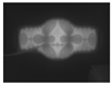 | 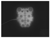 |  |
| CNT |  0.823 |  0.892 |  0.745 |
| GMG |  0.845 |  0.796 |  0.733 |
| GSOC |  0.880 |  0.971 |  0.803 |
| LSBP |  0.877 |  0.947 |  0.791 |
| MOG |  0.825 |  0.928 |  0.739 |
| KNN |  0.868 |  0.975 |  0.823 |
| SDPH ( n = 3) |  0.865 |  0.972 |  0.805 |
| SDPH ( n = 10) | 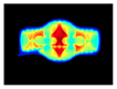 0.887 |  0.977 |  0.819 |
| Type | Abdominal Pad | Cervical Pad 2 | Patellar Pad |
|---|---|---|---|
| Photo | 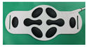 |  | 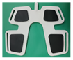 |
| Ideal |  |  |  |
| LWIR ( t = 50 min) | 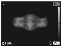 | 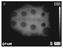 | 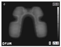 |
| CNT |  0.716 |  0.685 |  0.768 |
| GMG |  0.753 |  0.715 |  0.784 |
| GSOC |  0.765 |  0.851 |  0.766 |
| LSBP |  0.778 |  0.844 |  0.771 |
| MOG |  0.797 |  0.807 |  0.745 |
| KNN |  0.782 |  0.843 |  0.773 |
| SDPH ( n = 3) |  0.834 |  0.895 |  0.773 |
| SDPH ( n = 10) |  0.821 | 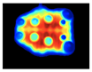 0.900 | 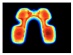 0.777 |
Disclaimer/Publisher’s Note: The statements, opinions and data contained in all publications are solely those of the individual author(s) and contributor(s) and not of MDPI and/or the editor(s). MDPI and/or the editor(s) disclaim responsibility for any injury to people or property resulting from any ideas, methods, instructions or products referred to in the content. |
© 2025 by the authors. Licensee MDPI, Basel, Switzerland. This article is an open access article distributed under the terms and conditions of the Creative Commons Attribution (CC BY) license (https://creativecommons.org/licenses/by/4.0/).
Share and Cite
Kim, H.; Song, J.-i.; Seo, J.-w.; Ko, C.; Seo, G.-h.; Han, S.K. Digitalized Thermal Inspection Method of the Low-Frequency Stimulation Pads for Preventing Low-Temperature Burn in Sensitive Skin. Bioengineering 2025, 12, 560. https://doi.org/10.3390/bioengineering12060560
Kim H, Song J-i, Seo J-w, Ko C, Seo G-h, Han SK. Digitalized Thermal Inspection Method of the Low-Frequency Stimulation Pads for Preventing Low-Temperature Burn in Sensitive Skin. Bioengineering. 2025; 12(6):560. https://doi.org/10.3390/bioengineering12060560
Chicago/Turabian StyleKim, HyungTae, Jong-ik Song, Ji-won Seo, CheolWoong Ko, Gi-ho Seo, and Sang Kuy Han. 2025. "Digitalized Thermal Inspection Method of the Low-Frequency Stimulation Pads for Preventing Low-Temperature Burn in Sensitive Skin" Bioengineering 12, no. 6: 560. https://doi.org/10.3390/bioengineering12060560
APA StyleKim, H., Song, J.-i., Seo, J.-w., Ko, C., Seo, G.-h., & Han, S. K. (2025). Digitalized Thermal Inspection Method of the Low-Frequency Stimulation Pads for Preventing Low-Temperature Burn in Sensitive Skin. Bioengineering, 12(6), 560. https://doi.org/10.3390/bioengineering12060560