

The Utah Manipulation and Locomotion of Large Objects (MeLLO) Data Library

 ,
,
Abstract
1. Introduction
2. Motivation
3. Related Work
3.1. Haptics
3.2. Similar Databases
4. Tasks
5. Methods and Procedures
5.1. Motion Capture Volume
5.2. Marker Set
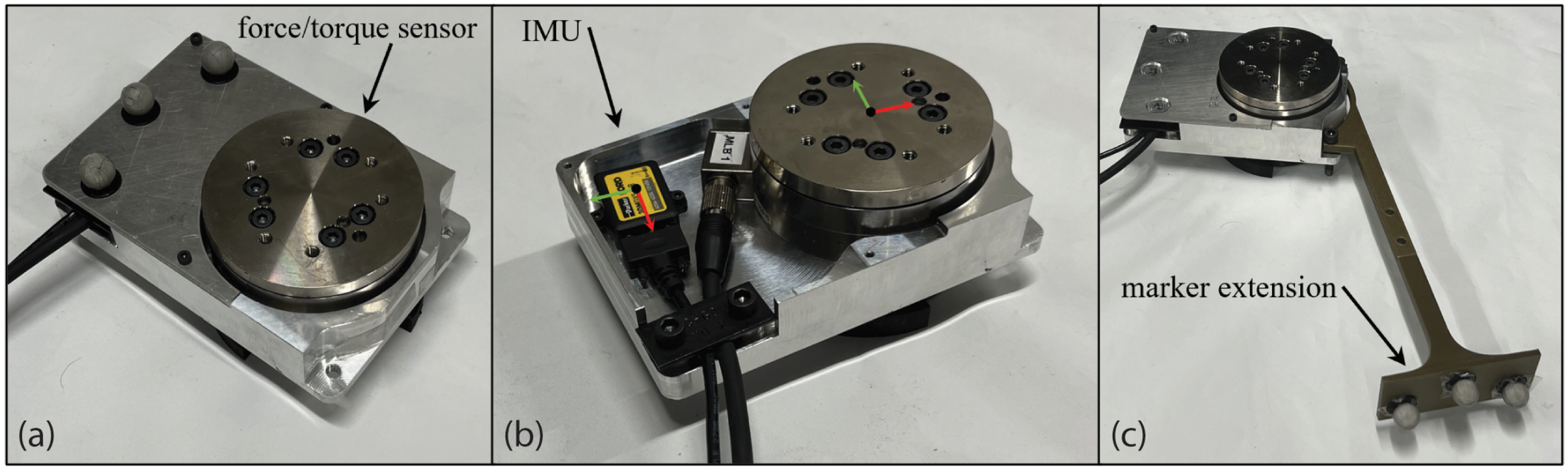
5.3. Instrumentation and Syncronization
5.4. Object Instrumentation
5.4.1. Box
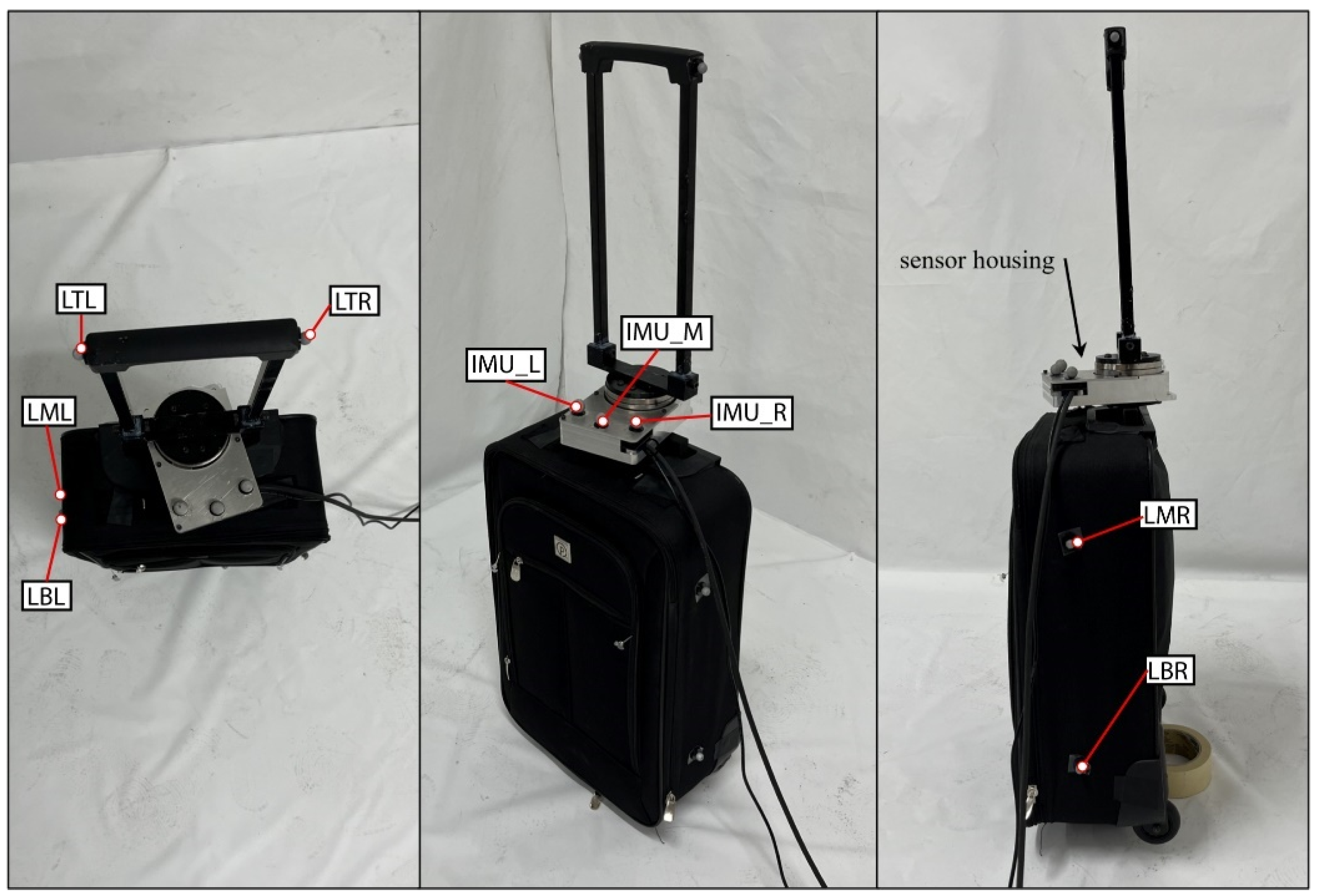
5.4.2. Luggage
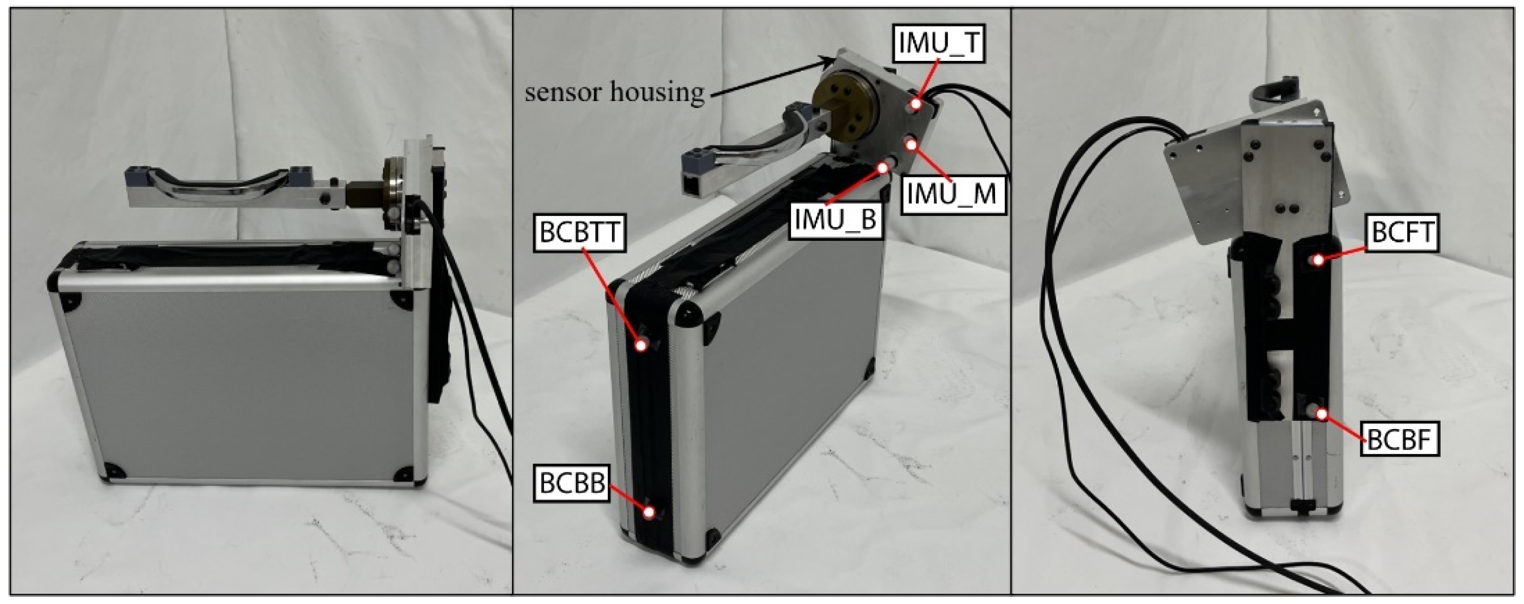
5.4.3. Briefcase
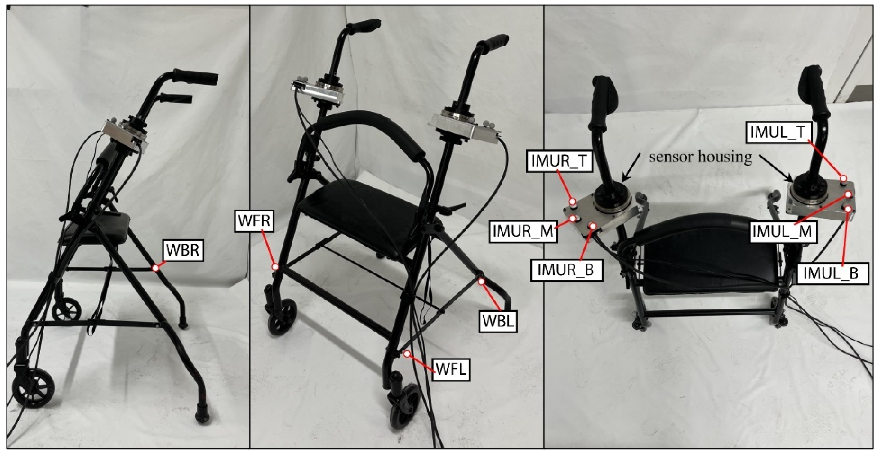
5.4.4. Walker
5.4.5. Shopping Cart
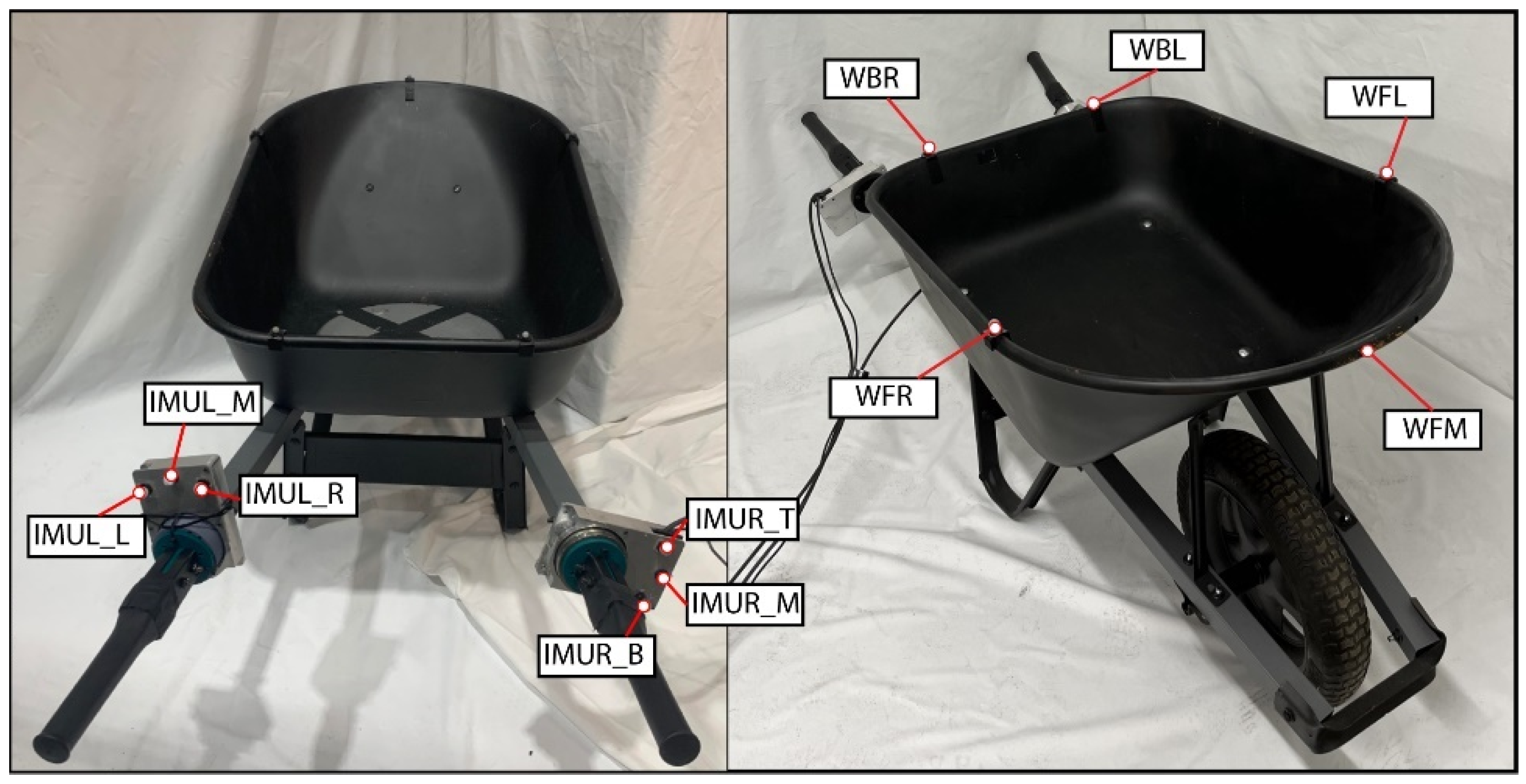
5.4.6. Wheelbarrow
5.4.7. Door
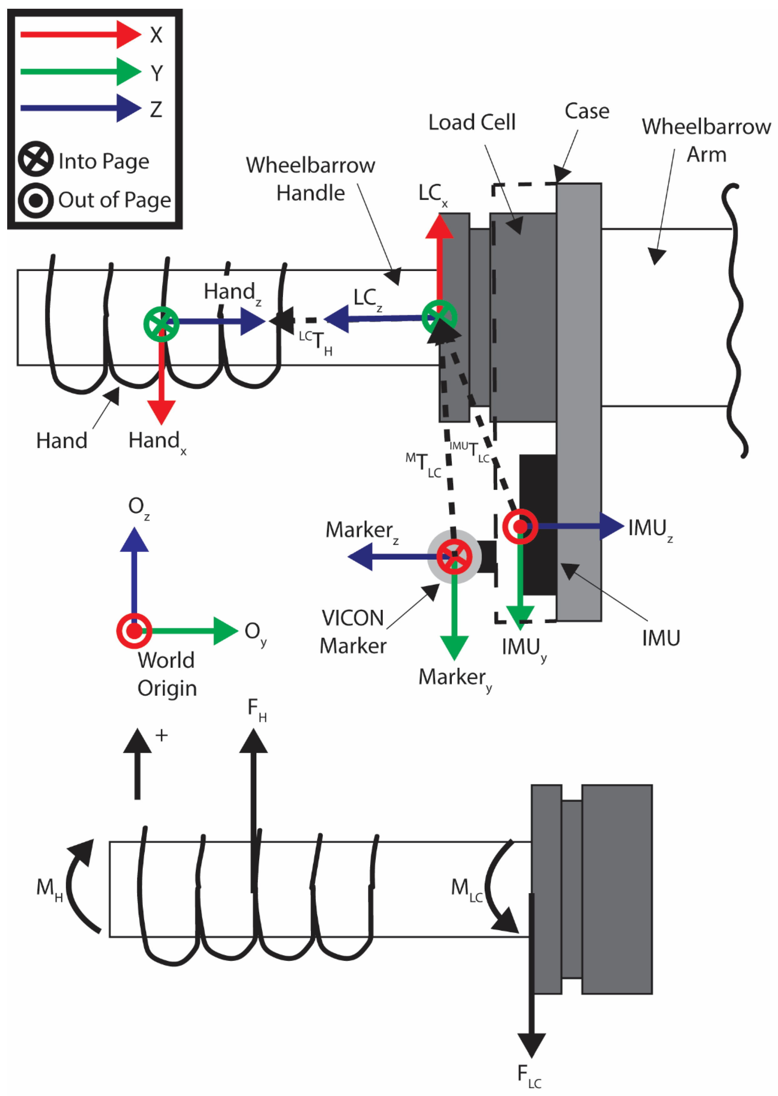
5.5. Transformations
5.6. Object Interaction Protocols
- (1)
- Box: The box had two types of interactions. The first was lifting. The box was sitting on a stand. The subject started standing straight up, then bent down and grabbed the sides of the box with an oppositional two-handed grasp and then lifted the box. They then lowered the box back down to the stand, let go, and stood back up. In the second interaction, the subject carried the box while walking. The subject started at one end of the capture volume holding the box with a two-handed oppositional grasp, and then walked through the volume. They started with their left foot and walked to the other side of the volume with a steady gait while holding the box.
- (2)
- Luggage: The subject started at one end of the capture value holding the handle of the luggage. They then walked through the capture volume, pulling the roller luggage behind them. They began walking with their left foot first, while keeping a steady gait until they reached the other side of the capture volume.
- (3)
- Briefcase: The briefcase had two different types of interactions. The first was lifting. At the start, the subject was standing straight up, then bent down and grabbed the handle, and then lifted the briefcase. They then lowered the briefcase to the ground, let go, and stood back up. In the second interaction, the subject carried the briefcase while walking. They started at one end of the capture volume while holding the briefcase in their right hand. They then walked, starting with their left foot, through the volume to the other side, with a steady gait, while holding the briefcase.
- (4)
- Walker: In this interaction, the subject walked through the motion capture volume using the walker for support. They started at one end of the volume with their hands grasping the walker handles. The subject then lifted the handles slightly and pushed the roller walker forward while extending their arms. They set the handles down and then applied downward force on the handles to support their weight while stepping towards the walker. The process was repeated until the subject traversed the capture volume.
- (5)
- Shopping cart: The subject approached the shopping cart and then pushed it through the motion capture volume. The subject started in a standing position a step back from the shopping cart. They stepped towards the cart and placed their hands on its handles; both of their arms were lifted up and grasped the shopping cart. They then pushed the shopping cart through the volume while walking.
- (6)
- Wheelbarrow: The wheelbarrow had two types of interactions. The first was lifting the handles. The subject started in a standing position between the handles. They then bent down, grabbed the handles, and lifted the wheelbarrow handles. The handles were then lowered until the back of the wheelbarrow again contacted the ground. The subject then released the handles and stood back up. In the second task, the subject pushed the wheelbarrow through the volume while walking. The subject started at one end of the capture volume while holding the wheelbarrow handles, meaning that the back of the wheelbarrow was lifted and the front was balanced on its wheel. They then walked through the volume while pushing the wheelbarrow. They started walking with their left foot, developed a steady gait, and pushed the wheelbarrow through the capture volume.
- (7)
- Door: The subject walked up to the door, opened it, stepped through, and released the door handle. They began standing a few steps away from the door. Unlike the other walking trials, the subject first took a step with their right foot due to the location of the door so they could more naturally open the door and step through it. After the right step, they stepped with their left foot towards the door while also reaching with their right hand to grasp the door handle. They then pushed the door open with their right hand and walked through, with their left foot leading. This is due to the fact that it was a right-handed door, meaning that the hinge was on the right side of the door and the handle and opening were on the left side. They then finished stepping through the door with their right foot and released the handle, allowing it to start closing. They then took a half step with their left foot, such that it evened up with their right foot. The subject was then standing straight up, and the door had closed behind them.
- (8)
- Gait: Natural gait was also measured, since so many of the tasks involved walking with objects. This allowed a baseline comparison in future studies so that the effect of handling the objects could be considered. The subject stood at one end of the capture volume and started walking with their left foot. They walked across the capture volume and their gait was recorded.
6. Data Processing
6.1. VICON
6.2. AddBiomechanics
6.3. dSpace/Load Cells
6.4. IMU
6.5. Final Data Synchronization and Export
- VICON trajectory CSV,
- VICON trigger data CSV,
- Cut VICON trajectory CSV,
- AddBiomechanics MOT motion file,
- Load cell MAT file,
- IMU CSV file.
7. Results
7.1. Subjects
7.2. Datasets
- (1)
- The main dataset is located on GitHub and SimTK and contains all the files described in Section 6 and shown in Figure 13. Data are arranged by subject, object, and task. The AddBiomechanics folder contains the data generated from the AddBiomechanics which is the marker error (CSV), motion files (MOT), and PDFs that show a preview of the data in the motion files. The cut VICON data folder contains the windowed marker data from VICON (CSV/C3D). The dSpace data contains an MAT file of each load cell and additional data needed for time syncing. The full VICON data folder contains the whole marker trajectory file for each task (CSV/C3D) and the trigger data file for syncing (CSV). The IMU data folder contains the IMU sensor data (CSV). The final data folder contains the synced AddBiomechanics full body joint and segment angles (CSV), the force and torque from the load cells (CSV), and the IMU data (CSV) of the windows of the VICON data. The entire library of data is available on GitHub and SimTK.
- (2)
- The AddBiomechanics data are also available on the AddBiomechanics website and contain everything that is processed through AddBiomechanics, as shown in Figure 13. It also contains the uploaded files used to generate the AddBiomechanics data. It contains the PDF, the marker errors, and the motion files described above. It contains the marker data in a (TRC) file and the OpenSim models used to obtain this information. AddBiomechanics is provided so that other researchers can evaluate the data processing, and have ready access to raw and processed data.
- (3)
- The main dataset is also available on GitHub and SimTK, and contains everything that is in the main database file described above. There is also the OpenSim model used for AddBiomechanics (OSIM), example processing code (MATLAB), and the homogeneous transformations (CSV) described in Section 5.5, which are available in the library.
7.3. Data Sample
7.4. Data Analysis Example: Wheelbarrow
7.4.1. Time Series Data: Wheelbarrow Lift
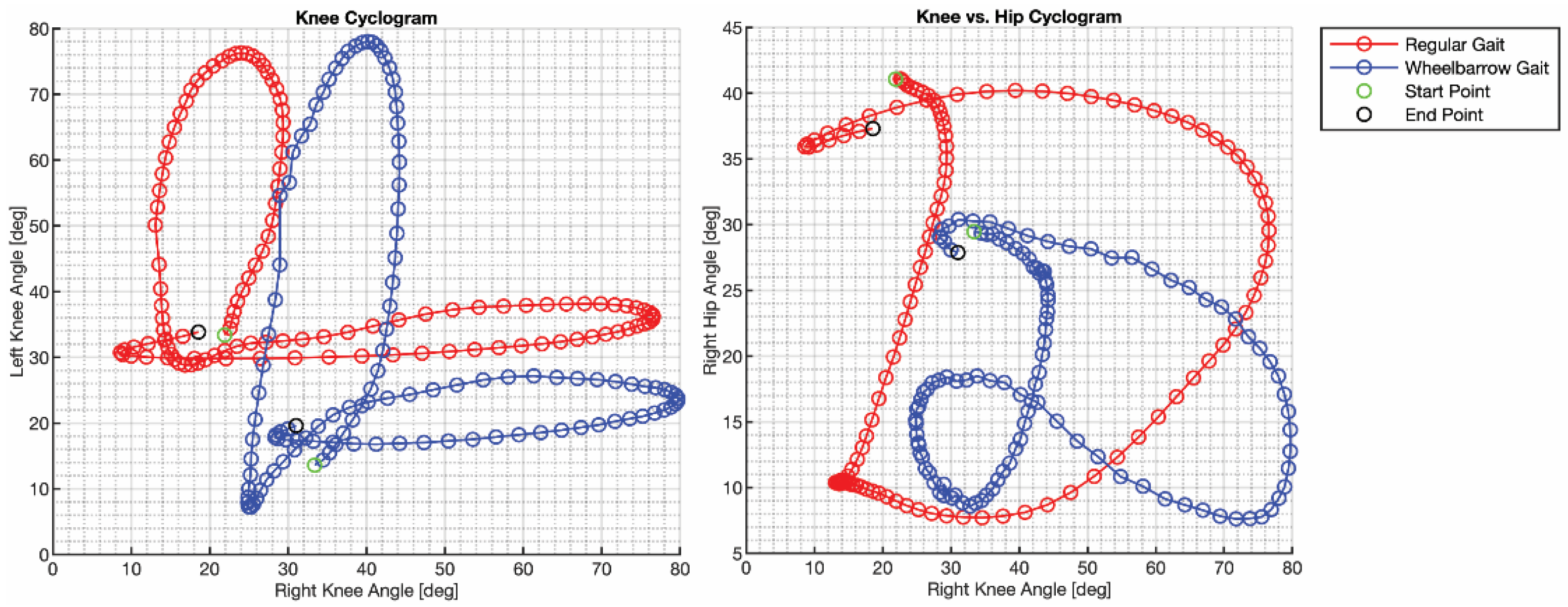
7.4.2. Gait Characterization: Regular Gait vs. Wheelbarrow Gait
8. Conclusions
Author Contributions
Funding
Institutional Review Board Statement
Informed Consent Statement
Data Availability Statement
Acknowledgments
Conflicts of Interest
References
- Feix, T.; Bullock, I.M.; Dollar, A.M. Analysis of human grasping behavior: Object characteristics and grasp type. IEEE Trans. Haptics 2014, 7, 311–323. [Google Scholar] [CrossRef] [PubMed]
- Mandery, C.; Terlemez, Ö.; Do, M.; Vahrenkamp, N.; Asfour, T. The KIT whole-body human motion database. In Proceedings of the 2015 International Conference on Advanced Robotics (ICAR), Istanbul, Turkey, 27–31 July 2015; pp. 329–336. [Google Scholar]
- Mandery, C.; Terlemez, Ö.; Do, M.; Vahrenkamp, N.; Asfour, T. Unifying representations and large-scale whole-body motion databases for studying human motion. IEEE Trans. Robot. 2016, 32, 796–809. [Google Scholar] [CrossRef]
- Meixner, A.; Krebs, F.; Jaquier, N.; Asfour, T. An Evaluation of Action Segmentation Algorithms on Bimanual Manipulation Datasets. In Proceedings of the 2023 IEEE/RSJ International Conference on Intelligent Robots and Systems (IROS), Detroit, MI, USA, 1–5 October 2023; pp. 4912–4919. [Google Scholar]
- Kang, S.; Ishihara, K.; Sugimoto, N.; Morimoto, J. Curriculum-based humanoid robot identification using large-scale human motion database. Front. Robot. AI 2023, 10, 1282299. [Google Scholar] [CrossRef]
- Krebs, F.; Asfour, T. A bimanual manipulation taxonomy. IEEE Robot. Autom. Lett. 2022, 7, 11031–11038. [Google Scholar] [CrossRef]
- Emami, M.; Bayat, A.; Tafazolli, R.; Quddus, A. A survey on haptics: Communication, sensing and feedback. IEEE Commun. Surv. Tutor. 2024. [Google Scholar] [CrossRef]
- Varalakshmi, B.; Thriveni, J.; Venugopal, K.; Patnaik, L. Haptics: State of the art survey. Int. J. Comput. Sci. Issues 2012, 9, 234. [Google Scholar]
- El Saddik, A. The potential of haptics technologies. IEEE Instrum. Meas. Mag. 2007, 10, 10–17. [Google Scholar] [CrossRef]
- Truong, T.E.; Luttmer, N.G.; Eshete, E.R.; Zaki, A.B.M.; Greer, D.D.; Hirschi, T.J.; Stewart, B.R.; Gregory, C.A.; Minor, M.A. Evaluating the Effect of Multi-Sensory Stimulation on Startle Response Using the Virtual Reality Locomotion Interface MS.TPAWT. Virtual Worlds 2022, 1, 62–81. [Google Scholar] [CrossRef]
- Russo, M.; Lee, J.; Hogan, N.; Sternad, D. Mechanical effects of canes on standing posture: Beyond perceptual information. J. neuroeng. Rehabil. 2022, 19, 1–13. [Google Scholar] [CrossRef]
- McClain, E.W. Simulation and Control of a Human Assistive Quadrupedal Robot. PhD Thesis, The University of Utah, Salt Lake City, UT, USA, 2022. [Google Scholar]
- Zhu, W.; Ma, X.; Ro, D.; Ci, H.; Zhang, J.; Shi, J.; Gao, F.; Tian, Q.; Wang, Y. Human motion generation: A survey. IEEE Trans. Pattern Anal. Mach. Intell. 2023, 46, 2430–2449. [Google Scholar] [CrossRef]
- Bassani, G.; Filippeschi, A.; Avizzano, C.A. A Dataset of Human Motion and Muscular Activities in Manual Material Handling Tasks for Biomechanical and Ergonomic Analyses. IEEE Sens. J. 2021, 21, 24731–24739. [Google Scholar] [CrossRef]
- Geissinger, J.H.; Asbeck, A.T. Motion inference using sparse inertial sensors, self-supervised learning, and a new dataset of unscripted human motion. Sensors 2020, 20, 6330. [Google Scholar] [CrossRef] [PubMed]
- Kang, P.; Zhu, K.; Jiang, S.; He, B.; Shull, P. HBOD: A Novel Dataset with Synchronized Hand, Body, and Object Manipulation Data for Human-Robot Interaction. In Proceedings of the 2023 IEEE 19th International Conference on Body Sensor Networks (BSN), Boston, MA, USA, 9–11 October 2023; pp. 1–4. [Google Scholar]
- Maurice, P.; Malaisé, A.; Amiot, C.; Paris, N.; Richard, G.-J.; Rochel, O.; Ivaldi, S. Human movement and ergonomics: An industry-oriented dataset for collaborative robotics. Int. J. Robot. Res. 2019, 38, 1529–1537. [Google Scholar] [CrossRef]
- Bhatnagar, B.L.; Xie, X.; Petrov, I.A.; Sminchisescu, C.; Theobalt, C.; Pons-Moll, G. Behave: Dataset and method for tracking human object interactions. In Proceedings of the IEEE/CVF Conference on Computer Vision and Pattern Recognition, 19–20 June 2022; pp. 15935–15946. [Google Scholar]
- Wang, Y.; Truong, T.E.; Chesebrough, S.W.; Willemsen, P.; Foreman, K.B.; Merryweather, A.S.; Hollerbach, J.M.; Minor, M.A. Augmenting virtual reality terrain display with smart shoe physical rendering: A pilot study. IEEE Trans. Haptics 2020, 14, 174–187. [Google Scholar] [CrossRef]
- Sabetian, P. Modular Cable-Driven Robot Development and Its Applications in Locomotion and Rehabilitation. Ph.D. Thesis, The University of Utah, Salt Lake City, UT, USA, 2019. [Google Scholar]
- Duffell, L.D.; Hope, N.; McGregor, A.H. Comparison of kinematic and kinetic parameters calculated using a cluster-based model and Vicon’s plug-in gait. Proc. Inst. Mech. Eng. Part H J. Eng. Med. 2014, 228, 206–210. [Google Scholar] [CrossRef]
- Goldfarb, N.; Lewis, A.; Tacescu, A.; Fischer, G.S. Open source Vicon Toolkit for motion capture and Gait Analysis. Comput. Methods Programs Biomed. 2021, 212, 106414. [Google Scholar] [CrossRef]
- Hollerbach, J.M. Introduction to Robotics: Chapter 7: Velocity and Acceleration. University of Utah. Available online: https://my.eng.utah.edu/~cs5310/files/chapter7.pdf (accessed on 29 January 2025).
- Werling, K.; Bianco, N.A.; Raitor, M.; Stingel, J.; Hicks, J.L.; Collins, S.H.; Delp, S.L.; Liu, C.K. AddBiomechanics: Automating model scaling, inverse kinematics, and inverse dynamics from human motion data through sequential optimization. PLoS ONE 2023, 18, e0295152. [Google Scholar] [CrossRef]
- Rajagopal, A.; Dembia, C.L.; DeMers, M.S.; Delp, D.D.; Hicks, J.L.; Delp, S.L. Full-body musculoskeletal model for muscle-driven simulation of human gait. IEEE Trans. Biomed. Eng. 2016, 63, 2068–2079. [Google Scholar] [CrossRef]
- Foreman, K.B.; Wilson, C.; Dibble, L.E.; Merryweather, A.S. Training persons with Parkinson disease using an advanced CAVE virtual reality system. FASEB J. 2019, 33, 335.4. [Google Scholar] [CrossRef]
- Arippa, F.; Leban, B.; Monticone, M.; Cossu, G.; Casula, C.; Pau, M. A study on lower limb asymmetries in Parkinson’s disease during gait assessed through kinematic-derived parameters. Bioengineering 2022, 9, 120. [Google Scholar] [CrossRef]
- Chesebrough, S.W. Robot-Assisted Gait Rehabilitation Using Virtual Reality with Torso Force Feedback. Ph.D. Thesis, The University of Utah, Salt Lake City, UT, USA, 2018. [Google Scholar]
- Hollerbach, J.M.; Mills, R.; Tristano, D.; Christensen, R.R.; Thompson, W.B.; Xu, Y. Torso force feedback realistically simulates slope on treadmill-style locomotion interfaces. Int. J. Robot. Res. 2001, 20, 939–952. [Google Scholar] [CrossRef]
- Stoica, P.; Moses, R.L. Spectral Analysis of Signals; Pearson Prentice Hall: Upper Saddle River, NJ, USA, 2005; Volume 452. [Google Scholar]
- Luttmer, N.G.; Truong, T.E.; Boynton, A.M.; Carrier, D.; Minor, M.A. Treadmill based three tether parallel robot for evaluating auditory warnings while running. In Proceedings of the 2020 IEEE International Conference on Robotics and Automation (ICRA), Paris, France, 31 May–31 August 2020; pp. 9135–9142. [Google Scholar]
- Luttmer, N.G.; Baum, N.I.; Flores-Gonzalez, J.; Hollerbach, J.M.; Minor, M.A. MeLLO Data Library (2025-present). GitHub. Available online: https://simtk.org/projects/mello-library/ (accessed on 4 March 2025).


| Database | Human Sensing | Haptic Sensing | Object Sensing | Object Size (S, M, L) | Similar Objects | Locomotion with Objects | Number of Subjects |
|---|---|---|---|---|---|---|---|
| Dataset of Human Motion and Muscular Activities [14] | IMU, sEMG | None | None | M | B | Yes | 14 |
| Dataset of Unscripted Human Motion [15] | IMU | None | None | S, M, L | B, D, SC | Yes | 13 |
| HBOD [16] | MoCap, IMU | None | MoCap | S, M | None | No | 5 |
| An Industry- Oriented Dataset [17] | IMU, MoCap | Pressure Sensor | None | S, M, L | None | Yes | 13 |
| BEHAVE [18] | RGBD Images | None | RGBD Images | S, M, L | B, L | No | 8 |
| KIT [2] | MoCap | None | MoCap | S, M, L | B | Yes | 43 |
| Our Database | MoCap | Load Cell | MocCap, IMU | M, L | B, D, BC, L, W, WB, SC | Yes | 6 |
| Joint | Minimum Angle (Degrees) | Maximum Angle (Degrees) | Range of Motion (Degrees) |
|---|---|---|---|
| Hip | 12.5 ± 8.2 | 75.3 ± 7.4 | 62.8 ± 7.3 |
| Knee | 15.5 ± 3.6 | 76.6 ± 6.8 | 61.1 ± 8.2 |
| Ankle | −14.1 ± 1.6 | 4.3 ± 5.0 | 18.4 ± 4.2 |
| Parameters | Regular Gait | Wheelbarrow Carry Gait |
|---|---|---|
| Step Length [m] | 0.66 ± 0.22 | 0.63 ± 0.03 |
| Step Time [s] | 0.58 ± 0.08 | 0.63 ± 0.04 |
| Stride Length [m] | 1.45 ± 0.04 | 1.24 ± 0.06 |
| Stride Time [s] | 1.21 ± 0.03 | 1.25 ± 0.05 |
| Walking Speed [m/s] | 1.20 ± 0.04 | 0.99 ± 0.06 |
| Cadence [steps/m] | 49.7 ± 1.15 | 48.0 ± 2.00 |
| Stride Frequency [strides/m] | 24.9 ± 0.56 | 24.0 ± 1.00 |
Disclaimer/Publisher’s Note: The statements, opinions and data contained in all publications are solely those of the individual author(s) and contributor(s) and not of MDPI and/or the editor(s). MDPI and/or the editor(s) disclaim responsibility for any injury to people or property resulting from any ideas, methods, instructions or products referred to in the content. |
© 2025 by the authors. Licensee MDPI, Basel, Switzerland. This article is an open access article distributed under the terms and conditions of the Creative Commons Attribution (CC BY) license (https://creativecommons.org/licenses/by/4.0/).
Share and Cite
Luttmer, N.G.; Baum, N.I.; Flores-Gonzalez, J.; Hollerbach, J.M.; Minor, M.A. The Utah Manipulation and Locomotion of Large Objects (MeLLO) Data Library. Bioengineering 2025, 12, 317. https://doi.org/10.3390/bioengineering12030317
Luttmer NG, Baum NI, Flores-Gonzalez J, Hollerbach JM, Minor MA. The Utah Manipulation and Locomotion of Large Objects (MeLLO) Data Library. Bioengineering. 2025; 12(3):317. https://doi.org/10.3390/bioengineering12030317
Chicago/Turabian StyleLuttmer, Nathaniel G., Nathan I. Baum, Josue Flores-Gonzalez, John M. Hollerbach, and Mark A. Minor. 2025. "The Utah Manipulation and Locomotion of Large Objects (MeLLO) Data Library" Bioengineering 12, no. 3: 317. https://doi.org/10.3390/bioengineering12030317
APA StyleLuttmer, N. G., Baum, N. I., Flores-Gonzalez, J., Hollerbach, J. M., & Minor, M. A. (2025). The Utah Manipulation and Locomotion of Large Objects (MeLLO) Data Library. Bioengineering, 12(3), 317. https://doi.org/10.3390/bioengineering12030317