

Computational Modeling of Diffusion-Based Delamination for Active Implantable Medical Devices

 ,
,  and
and
Abstract
1. Introduction
2. Materials and Methods
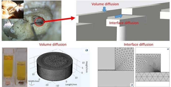
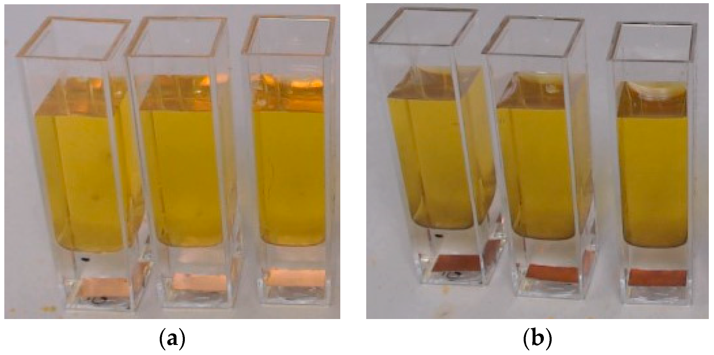
2.1. Volume Diffusion—Potassium Polysulfide Diffusion Test
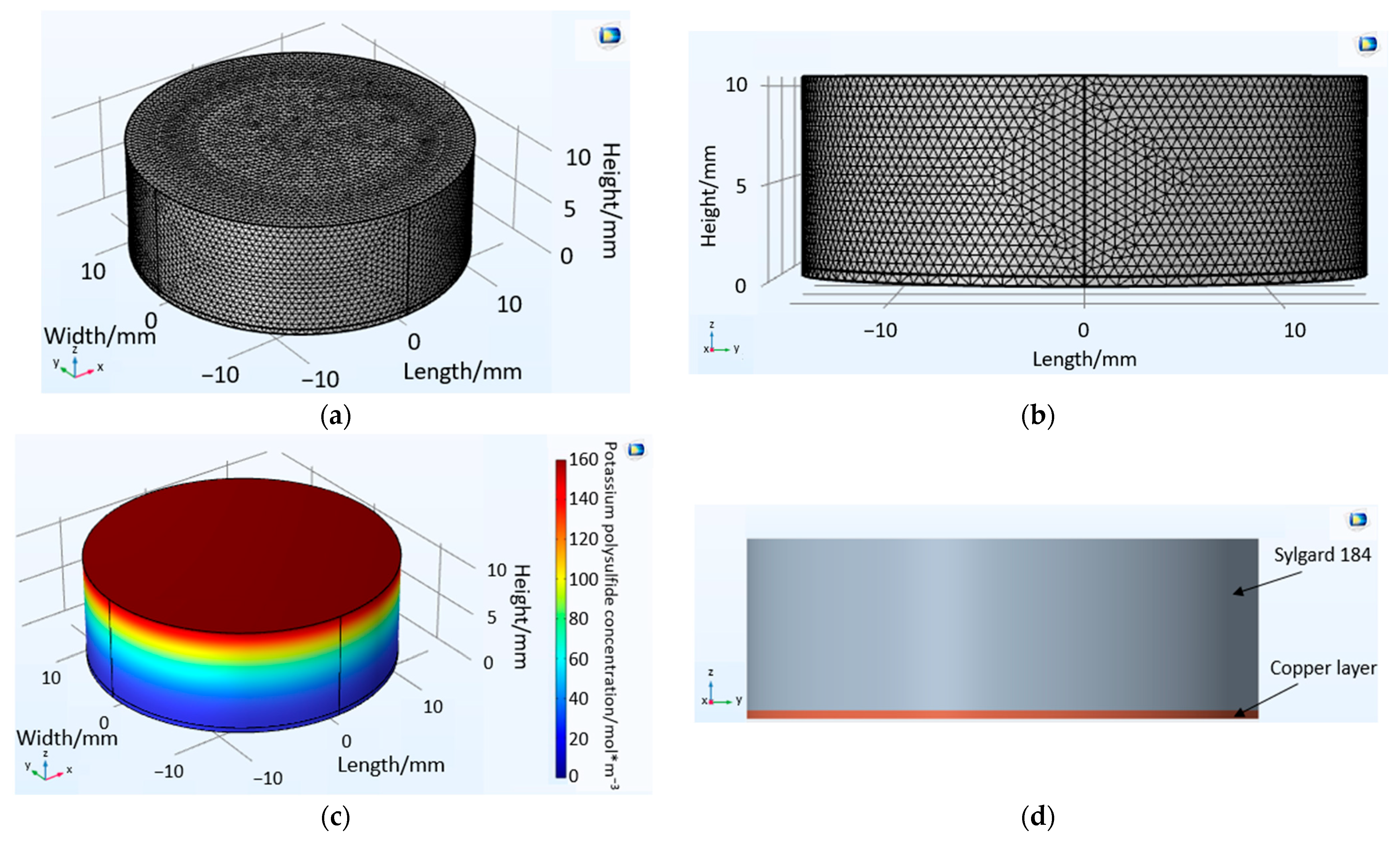
2.2. Volume Diffusion—Potassium Sulfide Diffusion COMSOL Model
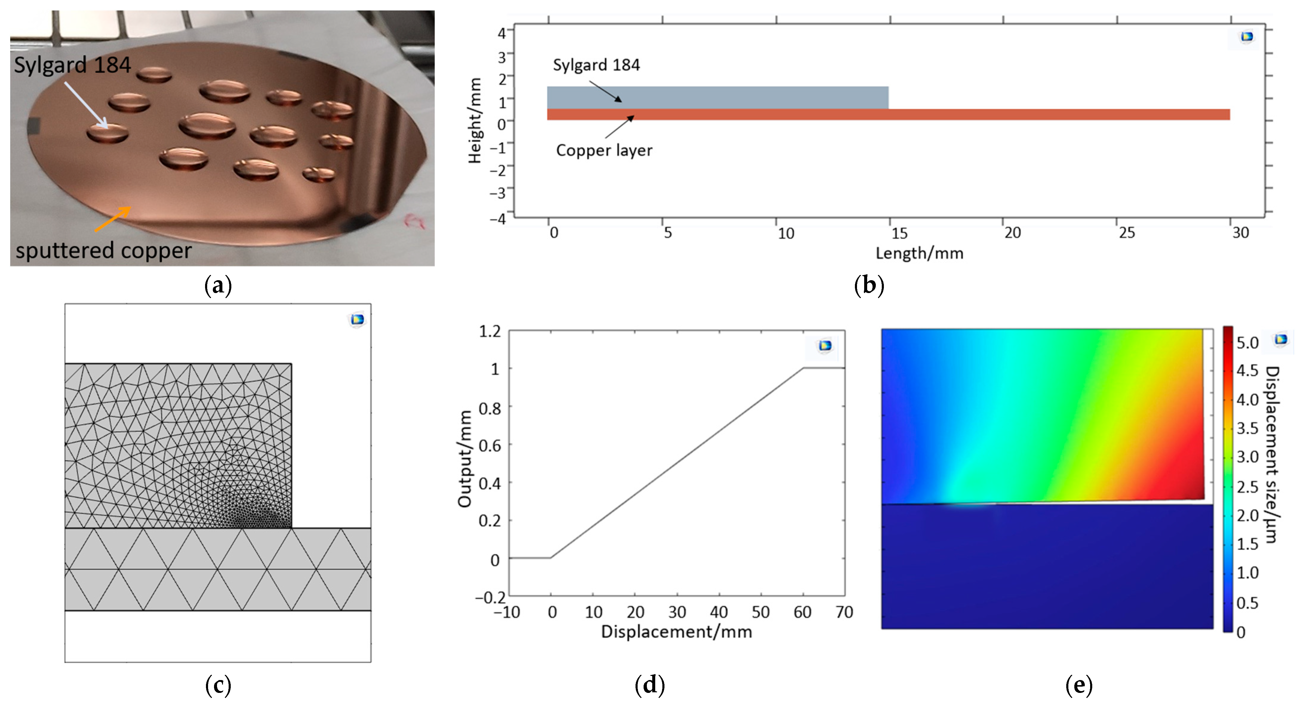
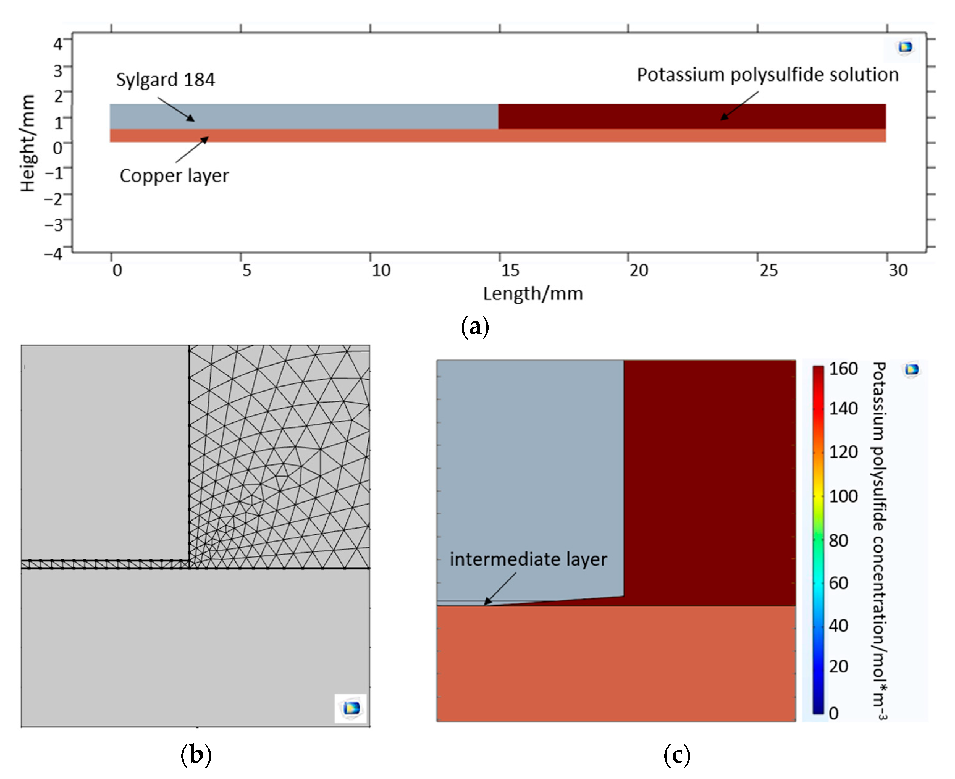
2.3. Modeling Diffusion along the Metal-Polymer Interfaces
2.3.1. Interface Delamination Model—Mechanical Approach
2.3.2. Interface Diffusion Model—Substance Transport-Based Approach
3. Results
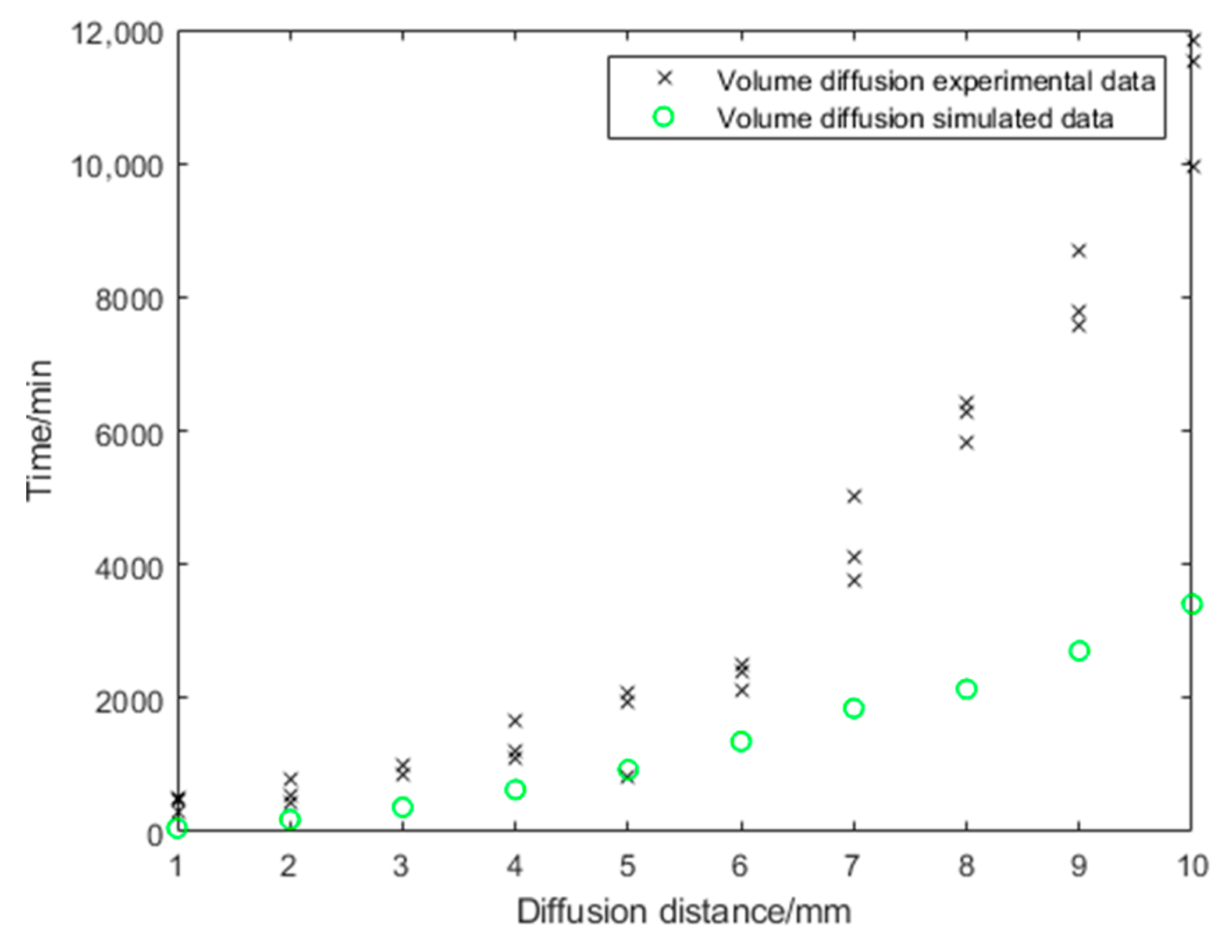
3.1. Volume Diffusion
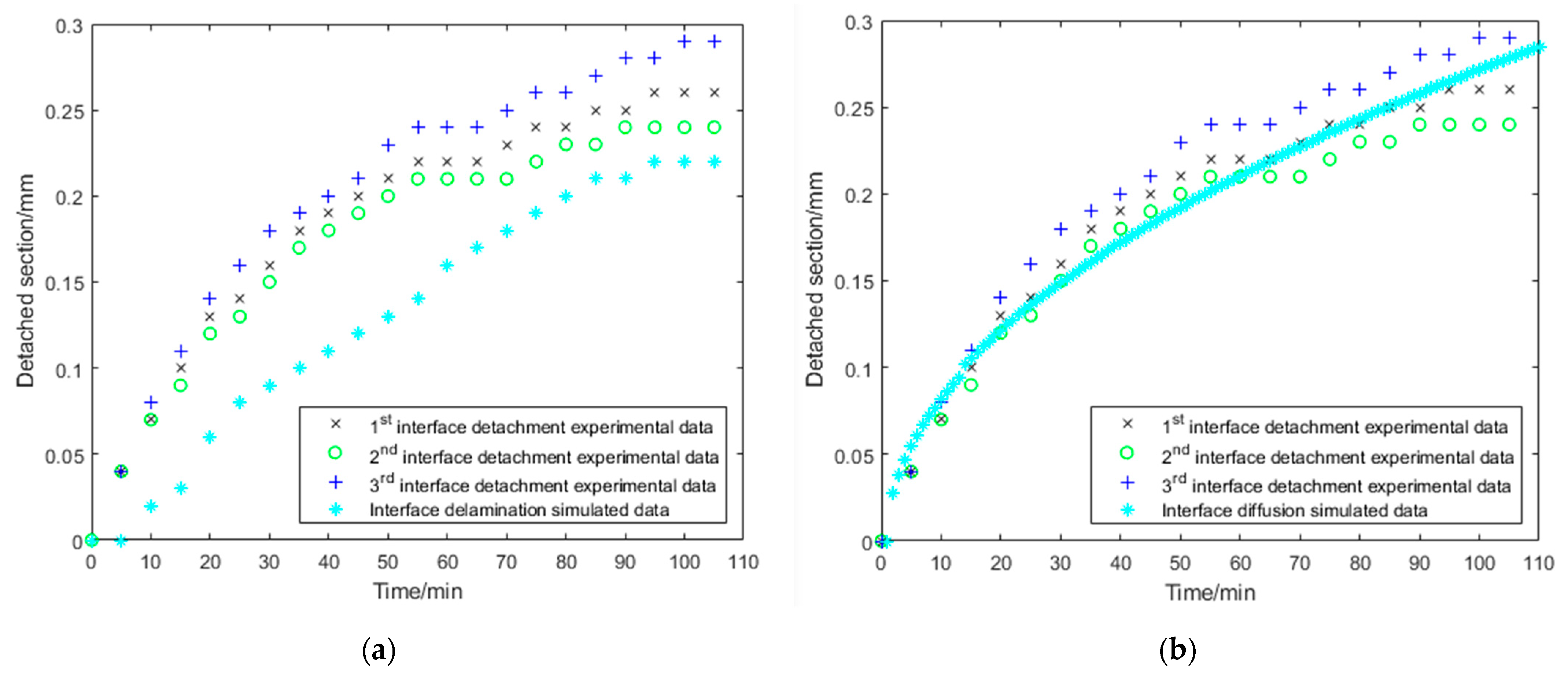
3.2. Interface Diffusion
4. Discussion
5. Conclusions
Author Contributions
Funding
Institutional Review Board Statement
Informed Consent Statement
Acknowledgments
Conflicts of Interest
References
- Boehler, C.; Carli, S.; Fadiga, L.; Stieglitz, T.; Asplund, M. Tutorial: Guidelines for standardized performance tests for electrodes intended for neural interfaces and bioelectronics. Nat. Protoc. 2020, 15, 3557–3578. [Google Scholar] [CrossRef]
- Stieglitz, T. Of Man and Mice: Translational Research in Neurotechnology. Neuron 2020, 105, 12–15. [Google Scholar] [CrossRef]
- Battmer, R.-D.; Linz, B.; Lenarz, T. A Review of Device Failure in More Than 23 Years of Clinical Experience of a Cochlear Implant Program With More Than 3,400 Implantees. Otol. Neurotol. 2009, 30, 455–463. [Google Scholar] [CrossRef] [PubMed]
- Stieglitz, T. Neuroprothetik und Neuromodulation: Forschungsansätze und klinische Praxis bei Therapie und Rehabilitation. Bundesgesundheitsblatt Gesundh. Gesundh. 2010, 53, 783–790. [Google Scholar] [CrossRef] [PubMed]
- Boenninghaus, H.-G.; Lenarz, T. Hals-Nasen-Ohren-Heilkunde: Jetzt neu mit Fallquiz, 13th ed.; Springer: Berlin/Heidelberg, Germany, 2007. [Google Scholar]
- Dhanasingh, A.; Jolly, C. An overview of cochlear implant electrode array designs. Heart Res. 2017, 356, 93–103. [Google Scholar] [CrossRef] [PubMed]
- Stöver, T.; Lenarz, T. Biomaterials in cochlear implants. GMS Curr. Top. Otorhinolaryngol. Head Neck Surg. 2011, 8, 62. [Google Scholar] [CrossRef]
- Wissel, K.; Brandes, G.; Pütz, N.; Angrisani, G.L.; Thieleke, J.; Lenarz, T.; Durisin, M. Platinum corrosion products from electrode contacts of human cochlear implants induce cell death in cell culture models. PLoS ONE 2018, 13, e0196649. [Google Scholar] [CrossRef]
- Durisin, M.; Lenarz, T.; Kanaan, N.; Bach, F.-W.; Angrisani, G.L.; Maier, H.J. Changes on a Platinum Elektrode Surface during Acoustic Stimulation of a Cochlear Implant—In Vitro Approach. Biomed. Technol. 2014, 59, S1115–S1119. [Google Scholar] [CrossRef]
- Kieninger, J.; Weltin, A.; Ganatra, D.; Maier, H.J.; Angrisani, L.; Steffens, M.; Wissel, K.; Warnecke, A.; Durisin, M. Electrode-Nerve Interfaces: Long-Term Stable Sensors and Electrode Corrosion. Biomed. Technol. 2018, 63, S139. [Google Scholar]
- Eliaz, N. Corrosion of Metallic Biomaterials: A Review. Materials 2019, 12, 407. [Google Scholar] [CrossRef]
- Mao, Y.; Pechenizkiy, I.; Stieglitz, T.; Doll, T. Numerical Evaluation on Residual Thermal Stress-Induced Delamination at PDMS–Metal Interface of Neural Prostheses. Micromachines 2021, 12, 669. [Google Scholar] [CrossRef] [PubMed]
- Doll, T.; Stieglitz, T. Modelling Electrochemical-Structural Failure Mechanisms in Active Implantable Medical Devices (AMID) Proc . BMT 2020, 54, 37. [Google Scholar]
- Durisin, M.; Krause, C.; Arnoldner, C.; Kontorinis, G.; Buechner, A.; Lenarz, T.; Lesinki-Schiedat, A.; Profant, O.; Neuburger, J. Electron microscopy changes of cochlear implant electrodes with permanently high impedances. Cochlea Implant. Int. 2011, 12, 228–233. [Google Scholar] [CrossRef]
- Foggia, M.J.; Quevedo, R.V.; Hansen, M.R. Intracochlear fibrosis and the foreign body response to cochlear implant biomaterials. Laryngoscope Investig. Otolaryngol. 2019, 4, 678–683. [Google Scholar] [CrossRef] [PubMed]
- Shi, L.; Zhu, G.; Ma, D.; Zhu, C.; Chen, J.; Qian, X.; Gao, X. Delayed postoperative complications in 624 consecutive cochlear implantation cases. Acta Oto-Laryngol. 2021, 141, 663–670. [Google Scholar] [CrossRef]
- Côté, M.; Ferron, P.; Bergeron, F.; Bussières, R. Cochlear Reimplantation: Causes of Failure, Outcomes, and Audiologic Performance. Laryngoscope 2007, 117, 1225–1235. [Google Scholar] [CrossRef]
- Lane, C.; Zimmerman, K.; Agrawal, S.; Parnes, L. Cochlear implant failures and reimplantation: A 30-year analysis and literature review. Laryngoscope 2019, 130, 782–789. [Google Scholar] [CrossRef]
- Kojic, M.; Filipovic, N.; Stojanovic, B.; Kojic, N. Computer Modelling in Bioengineering; Wiley: Chichester, UK, 2008. [Google Scholar]
- Dokos, S. Modelling Organs, Tissues, Cells and Devices Using MATLAB and COMSOL Multiphysics; Springer: Berlin/Heidelberg, Germany, 2017; ISBN 078-3-642-54800-0. [Google Scholar]
- Onken, A.; Schütte, H.; Wulff, A.; Lenz-Strauch, H.; Kreienmeyer, M.; Hild, S.; Stieglitz, T.; Gassmann, S.; Lenarz, T.; Doll, T. Predicting Corrosion Delamination Failure in Active Implantable Medical Devices: Analytical Model and Validation Strategy. Bioengineering 2021, 9, 10. [Google Scholar] [CrossRef]
- Crank, J. The Mathematics of Diffusion; Clarendon Press: Oxford, UK, 1976; pp. 310–316. [Google Scholar]
- Goodman, T.R. The Heat-Balance Integral and Its Application to Problems Involving a Change of Phase. J. Fluids Eng. 1958, 80, 335–342. [Google Scholar] [CrossRef]
- Goodman, T.R. Application of Integral Methods to Transient Nonlinear Heat Transfer. In Advances in Heat Transfer; Elsevier: Amsterdam, The Netherlands, 1964; Volume 1, pp. 51–122. [Google Scholar] [CrossRef]
- Jung, M.; Langer, U. Methode Der Finiten Elemente Für Ingenieure; Springer-Vieweg: Wiesbaden/Heidelberg, Germany, 2013; ISBN 9783658011000. [Google Scholar]
- Zienkiewicz, O.; Chueng, Y. The Finite Element Method in Structural and Continuum Mechanics; McGraw-Hill: London, UK, 1967. [Google Scholar]
- Stieghorst, T.J. Doll, Rheological Behavior of PDMS Silicone Rubber for 3D Printing of Medical Implants. Addit. Manuf. 2018, 24, 217–223. [Google Scholar]
- Menges, G.; Edmund, H.; Michaeli, W.; Schmachtenberg, E. Menges Werkstoffkunde Kunststoffe; Carl Hanser Verlag: Munich, Germany, 2011. [Google Scholar]
- Retting, W.; Laun, H.M. Kunststoff-Physik; Carl Hanser Verlag: Munich, Germany, 1991. [Google Scholar]
- Jeschow, P. Silicone Elastomers. Rapra Rev. Rep. 2001, 12, 77. [Google Scholar]
- Weh, B. Permeationseigenschaften von Polydimethylsiloxan-Membranen in Abhängigkeit von Der Netzbogenlänge; Universität Würzburg: Würzburg, Germany, 2002. [Google Scholar]
- Polmanteer, K.E. Silicone Rubber, Its Development and Technological Progress. Rubber Chem. Technol. 1988, 61, 470–502. [Google Scholar] [CrossRef]
- Trego, B.R.; Winnan, H.W. Silicone Rubbers. Rapra Technol. 1990, 3, 31. [Google Scholar]
- Baehr, H.D.; Stephan, K. Wärme- und Stoffübertragung. Lehrbuch; Springer: Berlin, Germany, 2019. [Google Scholar]
- Lauth, G.J. Einfhrung in Die Physik und Chemie der Grenzflchen und Kolloide; Springer: Berlin/Heidelberg, Germany, 2015. [Google Scholar]
- Crank, J.; Gupta, R.S. A Moving Boundary Problem Arising from the Diffusion of Oxygen in Absorbing Tissue. IMA J. Appl. Math. 1972, 10, 19–33. [Google Scholar] [CrossRef]
- Lu, C.; Sun, Y.; Harley, S.; Glascoe, E. Modeling Gas Transport and Reactions in Polydimethysiloxane. TOUGH Symp. 2012, 8, 1288–1296. [Google Scholar]
- Li, B.; Pan, F.; Fang, Z.; Liu, L.; Jiang, Z. Molecular Dynamics Simulation of Diffusion Behavior of Benzene/Water in PDMS-Calix[4]arene Hybrid Pervaporation Membranes. Ind. Eng. Chem. Res. 2008, 47, 4440–4447. [Google Scholar] [CrossRef]
- Heymann, D.K.; Springer, P.D.J.; Ebneth, D.H. Kunststoff-Metallisierung Handbuch Für Theorie Und Praxis; Eugen, G., Ed.; Leuze Verlag: Singapore, 1991; ISBN 3-87480-081-4. [Google Scholar]
- Ohrt, C. Freies Volumen an Polymer-Festkörper-Grenzflächen; ChristianAlbrechts-Universität zu Kiel: Kiel, Germany, 2015. [Google Scholar]
- Bischof, A.C.; Bauer, H.L. Haftfestigkeitsuntersuchungen an Metall-Polymer-Verbunden 1: Theoretische Und Experimentelle Grundlagen—Stand Und Grenzen Der Pruefmethoden. Plaste Und Kautsch. 1983, 37, 315–317. [Google Scholar]
- Liu, J.; Lai, Z.; Kristiansen, H.; Khoo, C. Overview of Conductive Adhesive Joining Technology in Electronics Packaging Applications. In Proceedings of the 3rd International Conference on Adhesive Joining and Coating Technology in Electronics Manufacturing 1998 (Cat. No.98EX180), Binghamton, NY, USA, 30 September 1998; pp. 1–18. [Google Scholar]
- Adams, R.D., 3rd (Ed.) Adhesive Bonding: Science, Technology and Applications; Woodhead Publishing: London, UK, 2005; ISBN 9781855737419. [Google Scholar]
- Haefer, R.A. Oberflächen- Und Dünnschicht-Technologie, Werkstoff Forschung Und Technik 5; Springer: Berlin/Heidelberg, Germany, 1987. [Google Scholar]
- Mann, D.A. Plasma Modifizierung von Kunststoffoberflächen Zur Haftfestigkeitssteigerung von Metallschichten. IPA-IAO Forsch. Und Prax. 1994, 189, 38–51. [Google Scholar]
- Bischof, C.; Bauer, A.; Possart, W.; Kapelle, R.; Schulze, R.D. Zur Adhäsion in Metall-Polymer-Grenzschichten und ihrer praktischen Nutzung. Acta Polym. 1989, 40, 214–221. [Google Scholar] [CrossRef]
- Possart, W. Adhesion—Current Research and Application; Possart, W., Ed.; Wiley-VCH Verlag GmbH & Co. KGaA: Weinheim, Germany, 2005; ISBN 3-527-31263-3. [Google Scholar]
- Wong, E.; Koh, S.; Lee, K.; Rajoo, R. Comprehensive treatment of moisture induced failure-recent advances. IEEE Trans. Electron. Packag. Manuf. 2002, 25, 223–230. [Google Scholar] [CrossRef]


| Properties | Copper | Sylgard-184 |
|---|---|---|
| Density | 8960 [kg/m3] | 2329 [kg/m3] |
| Poission ratio | 0.35 | 0.28 |
| Youngs Modulus | 110 × 109 [Pa] | 170 × 109 [Pa] |
| Name | Value | Description |
|---|---|---|
| 0.027 mm/ | Boundary coefficient | |
| r | 0.014 m | Radius of the PDMS droplet |
| 1.6761 × 10⁻¹⁰ m2/s | Interface diffusion coefficient |
| Mesh Parameter | Sylgard 184/Intermediate Layer Mesh | Copper Layer/Potassium Polysulfide Solution Mesh |
|---|---|---|
| Minimum mesh size | 6 × 10⁻³ mm | 0.54 mm |
| Maximum mesh size | 0.06 mm | 0.3 mm |
| Maximum mesh growth rate | 1.3 | 1.5 |
Disclaimer/Publisher’s Note: The statements, opinions and data contained in all publications are solely those of the individual author(s) and contributor(s) and not of MDPI and/or the editor(s). MDPI and/or the editor(s) disclaim responsibility for any injury to people or property resulting from any ideas, methods, instructions or products referred to in the content. |
© 2023 by the authors. Licensee MDPI, Basel, Switzerland. This article is an open access article distributed under the terms and conditions of the Creative Commons Attribution (CC BY) license (https://creativecommons.org/licenses/by/4.0/).
Share and Cite
Nguyen, M.-H.; Onken, A.; Wulff, A.; Foremny, K.; Torgau, P.; Schütte, H.; Hild, S.; Doll, T. Computational Modeling of Diffusion-Based Delamination for Active Implantable Medical Devices. Bioengineering 2023, 10, 625. https://doi.org/10.3390/bioengineering10050625
Nguyen M-H, Onken A, Wulff A, Foremny K, Torgau P, Schütte H, Hild S, Doll T. Computational Modeling of Diffusion-Based Delamination for Active Implantable Medical Devices. Bioengineering. 2023; 10(5):625. https://doi.org/10.3390/bioengineering10050625
Chicago/Turabian StyleNguyen, Minh-Hai, Adrian Onken, Anika Wulff, Katharina Foremny, Patricia Torgau, Helmut Schütte, Sabine Hild, and Theodor Doll. 2023. "Computational Modeling of Diffusion-Based Delamination for Active Implantable Medical Devices" Bioengineering 10, no. 5: 625. https://doi.org/10.3390/bioengineering10050625
APA StyleNguyen, M.-H., Onken, A., Wulff, A., Foremny, K., Torgau, P., Schütte, H., Hild, S., & Doll, T. (2023). Computational Modeling of Diffusion-Based Delamination for Active Implantable Medical Devices. Bioengineering, 10(5), 625. https://doi.org/10.3390/bioengineering10050625